Hoval ST1 Guide

Rotary heat exchangers
Instructions for installation, commissioning and maintenance
ST1
ST2
SC1
SE3
SH1
HM1

1 Use 3
1.1 Intended use .................................................................. 3
1.2 User group..................................................................... 3
2 Safety 4
2.1 Symbols......................................................................... 4
2.2 Operational safety.......................................................... 4
3 Delivery 5
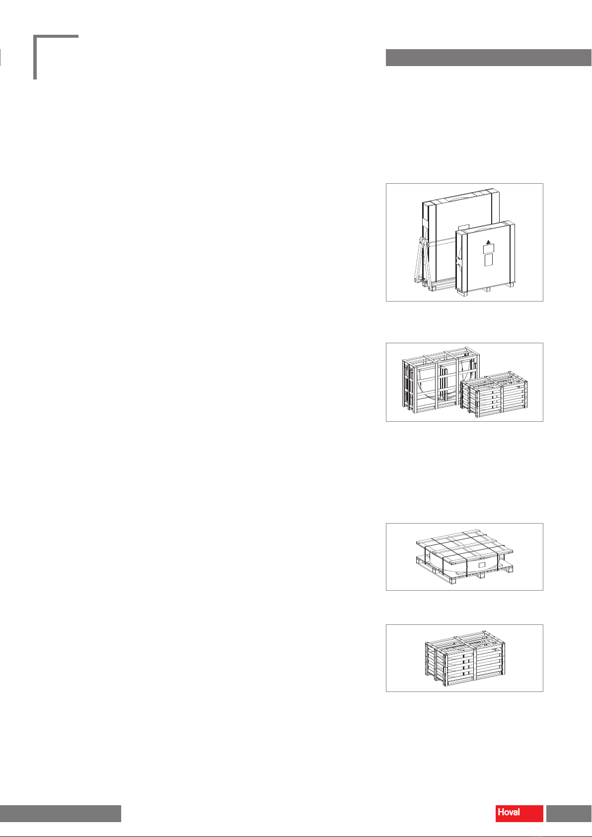
3.1 Scope of delivery ........................................................... 5
3.2 Identication and test..................................................... 6
3.3 Storage .......................................................................... 6
4 Tools and aids 6
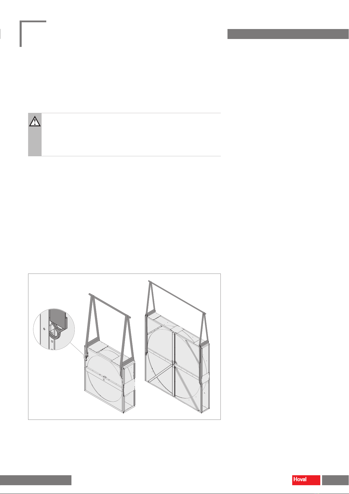
5 Lifting the exchanger 7
5.1 Lifting exchangers on pallets.......................................... 7
5.2 Lifting exchangers with SM casing................................. 7
5.3 Lifting exchangers with SP casing.................................. 8
5.4 Lifting exchangers with PR casing ................................. 9
5.5 Lifting wheels without casing........................................ 10
6 Installation of segmented exchangers 11
6.1 Casing...........................................................................11
6.2 Radial walls.................................................................. 14
6.3 Storage mass............................................................... 16
6.4 Purge sector ................................................................ 20
6.5 Seal ............................................................................. 22
6.6 Drive system ................................................................ 23
7 Installation in the air handling unit 26
7.1 Requirements for the installation site ........................... 26
7.2 Vertical installation ....................................................... 26
8 Electrical connection 27
9 Commissioning 28
9.1 Checklist ...................................................................... 28
9.2 Monitoring work after 2 weeks...................................... 28
10 Maintenance and repair 29
10.1 Maintenance schedule ............................................... 29
10.2 Cleaning..................................................................... 29
10.3 Spare parts ................................................................ 29
10.4 Replacement of the brush seal................................... 29
10.5 Replacement of the V-belt.......................................... 30
10.6 Repair ........................................................................ 30
2
Rotary heat exchangers
Instructions for installation, commissioning and maintenance
4 219 613-en-00 4 219 613-en-00
Content

1 Use
1.1 Intended use
Rotary heat exchangers
Hoval rotary heat exchangers are energy recovery units for installation in venti-
lation and air-conditioning units and for process engineering applications. They
transfer energy through a rotating storage mass, which is alternately heated by
one air stream and cooled by the other. The following application limits apply in
operation:
Temperature
without controller -20…50 °C
with controller -20…45 °C
Pressure difference between the air flows max. 1000 Pa
Pressure difference to outside max. 1000 Pa
Pressure drop
1-piece wheels max. 300 Pa
Segmented wheels max. 400 Pa
Table 1: Application limits
Wheels without casing
Hoval wheels without casing are energy recovery components for installation in
ventilation and air-conditioning units and for applications in process engineering.
The following application limits apply in operation:
Temperature -20…50 °C
Pressure drop
1-piece wheels max. 300 Pa
Segmented wheels max. 400 Pa
Table 2: Application limits
Intended use also includes compliance with these instructions. Any usage over
and above this use is considered to be not as intended. The manufacturer can
accept no liability for damage resulting from improper use.
1.2 User group
The rotary heat exchangers may only be installed and maintained by authorised
and instructed personnel who are well acquainted with the units and are informed
about possible dangers.
These instructions are for operating engineers and technicians as well as
specialists in building, heating and ventilation technology.
2 3
Rotary heat exchangers
Instructions for installation, commissioning and maintenance
Use
4 219 613-en-00

2 Safety
2.1 Symbols
Caution
This symbol warns against risk of injury. Please heed all instructions
designated by this symbol to prevent injuries and/or death.
Attention
This symbol warns against property damage. Please heed the respective
instructions to prevent risk of damage to the unit and its functions.
Notice
This symbol denotes information about the economic use of the equipment
or special tips.
2.2 Operational safety
The exchangers are constructed in accordance with the state of the art and are
safe to operate. Despite every precaution being taken, potential and not immedi-
ately obvious risks always remain, for example:
■Danger from suspended load
■Danger from trapping of body parts
■Danger from tilting
■Danger from sharp edges
■Danger from falling objects
■Danger when working on the electrical system
Therefore:
■Please read the instructions before unpacking, installing, commissioning and
maintaining the equipment.
■Store the operating instructions so that they are easily accessible.
■Observe any attached information and warning signs.
■Follow the local safety and accident prevention regulations at all times.
■The exchanger may only be installed, operated and serviced by authorised,
trained and instructed skilled personnel:
– Specialists as dened by these operating instructions are those persons
who, based on their training, knowledge and experience as well as their
knowledge of the relevant regulations and guidelines, can carry out the work
assigned to them and recognise potential hazards.
■Unauthorised reconguration or modication of the exchanger is not permitted.
4
Rotary heat exchangers
Instructions for installation, commissioning and maintenance
Safety
4 219 613-en-00 4 219 613-en-00

3 Delivery
3.1 Scope of delivery
Rotary heat exchangers are delivered on pallets and packaged in lm. The scope
of delivery includes:
1-piece rotary heat exchangers with casing:
■Rotary heat exchangers, fully assembled
■Optional components, placed in the casing (in the drive corner):
– Controller loose (CRLL)
– Spare sealing (SC)
– Spare belt (BX)
Segmented rotary heat exchangers with casing:
■Rotary heat exchanger in individual parts:
– Casing with shaft, bearing and hub, in 2 parts
– Radial walls
– Periphery plates
– Storage mass segments
– Screws for assembly
– Drive system (if applicable)
■Optional components, placed in the casing (in the drive corner):
– Purge sector (depending on the exchanger design)
– Controller loose (CRLL)
– Rotation guard (RG2 or RG3)
– Spare sealing (SC)
– Spare belt (BX)
1-piece wheels without casing
■Wheel, fully assembled
Segmented wheels without casing
■Wheel in individual parts:
– Shaft, bearing, hub (pre-assembled)
– Radial walls
– Periphery plates
– Storage mass segments
– Screws for assembly
Fig. 1: Delivery of 1-piece exchangers
Fig. 2: Delivery of segmented exchangers
Fig. 3: Delivery of 1-piece wheels
Fig. 4: Delivery of segmented wheels
4 5
Rotary heat exchangers
Instructions for installation, commissioning and maintenance
Safety Delivery
4 219 613-en-00

3.2 Identification and test
The type label contains important information for identifying the rotary heat
exchanger.
ST1-LL-SV-1200-PR-V7-A1-5
W1400,H1400,CCP,SHM,RG3
1201620906-020-01
201 45
2020
Hoval Aktiengesellschaft
9490 Vaduz
Liechtenstein
Made in EU
according to ISO 9001
in the Year
Type:
Typ:
Serial no.:
Serie-Nr.:
Net weight: Max. temperatur:
Nettogewicht: kg Max. Temperatur:
Purchase order no.:
Bestellnummer:
Customer material no.:
Kundenmaterialnummer:
°C
Max. pressure difference:
Max. Differenzdruck: 1000Pa
1 2 3 4 5 6
7
Fig. 5: Type label
■Check the consignment against the delivery documents and nameplate to
ensure that it is correct.
■Check the delivery for visible transport damage.
■Report any wrong deliveries and possible transport damage immediately in
writing.
3.3 Storage
If you do not install the exchanger immediately:
■Keep the exchanger in the original packaging.
■Place the exchanger on a level surface.
■Store the exchanger in a dry, dust-free room where it will not be subjected to
vibrations.
■Storage temperature: -20...50 °C (or max. 45 °C for exchangers with controller)
4 Tools and aids
The following tools and aids are required for assembly:
■Electrical screwdriver
■Drill ∅3.3 mm
■Pop rivet tool
■Set of Allen keys
■Scissors
■Spanner key set 10 - 19 mm
■Magnetic bit holder 8 mm
■Torque wrench 0 - 100 Nm
■Screw clamps
■Rubber mallet
■Personal protective equipment
■Lifting gear
■Measurement tape
■Threaded rod M10
■
1
Design
■
2
Wheel orientation
■
3
Wheel diameter
■
4
Casing type
■
5
Drive system
■
6
Purge sector
■
7
Options
6
Rotary heat exchangers
Instructions for installation, commissioning and maintenance
Tools and aids
4 219 613-en-00 4 219 613-en-00

5 Lifting the exchanger
Caution
Risk of injury caused by falling load, tilting of the exchanger or improper
handling. During all work:
– Wear protective equipment.
– Do not stand under suspended loads.
– Observe safety and accident prevention regulations.
5.1 Lifting exchangers on pallets
■Use a forklift with sucient load-bearing capacity.
■Make sure that the exchanger is securely attached to the forklift truck with
slings.
5.2 Lifting exchangers with SM casing
■Use lifting gear with sucient load-bearing capacity.
■Hook the snap hooks of the lifting gear into the lifting eyes on both sides of the
casing.
■Protect the exchanger casing with approx. 30 cm long square timbers.
Fig. 6: Exchangers with SM casing
6 7
Rotary heat exchangers
Instructions for installation, commissioning and maintenance
Tools and aids Lifting the exchanger
4 219 613-en-00

5.3 Lifting exchangers with SP casing
■Use lifting gear with sucient load-bearing capacity.
■Hook the snap hooks of the lifting gear into the lifting eyes on both sides of the
casing.
■Protect the exchanger casing with approx. 30 cm long square timbers.
Fig. 7: Exchangers with SP casing
Fig. 8: Exchangers with SP casing and option 'Half mounted' (SHM)
Fig. 9: Exchangers with SP casing and option 'Fully mounted' (SFM)
8
Rotary heat exchangers
Instructions for installation, commissioning and maintenance
Lifting the exchanger
4 219 613-en-00 4 219 613-en-00

5.4 Lifting exchangers with PR casing
■Use lifting gear with sucient load-bearing capacity.
■Screw the supplied lifting kits into the prole casing as shown below.
■Hook the snap hooks of the lifting gear into the lifting kits on both sides.
■Protect the exchanger casing with approx. 45 cm long square timbers.
Wheel Øup to 3799 mm Wheel Øup from 3800 mm
Fig. 10: Exchangers with PR casing
Fig. 11: Lifting kit
Fig. 12: Exchangers with PR casing and option
'Half mounted' (SHM)
Fig. 13: Exchangers with PR casing and option
'Fully mounted' (SFM)
8 9
Rotary heat exchangers
Instructions for installation, commissioning and maintenance
Lifting the exchanger Lifting the exchanger
4 219 613-en-00

5.5 Lifting wheels without casing
■Use lifting gear with sucient load-bearing capacity.
■The storage mass has 2 opposite drilled holes on the outside for lifting the wheel.
– Use metal rods (preferably smooth shafts) with 10 – 12 mm diameter and
approx. 200 mm length to lift the wheel.
– Insert the rods into the drilled holes and attach the lifting gear to them.
Attention
Danger of damaging the units.
Do not transport the wheels by rolling them.
Fig. 14: Wheels without casing
10
Rotary heat exchangers
Instructions for installation, commissioning and maintenance
Lifting the exchanger
4 219 613-en-00 4 219 613-en-00

6 Installation of segmented exchangers
Caution
Risk of injury caused by falling load, tilting of the exchanger or improper
handling. During all work:
– Wear protective equipment.
– Do not stand under suspended loads.
– Observe safety and accident prevention regulations.
6.1 Casing
■Place the bottom half of the casing on a level surface.
■Put on the top half of the casing.
■Screw the two parts together.
SP casing
4 x M5x16
4 x M5x16
8 x M5x40
Fig. 15: Installation of SP casings
10 11
Rotary heat exchangers
Instructions for installation, commissioning and maintenance
Lifting the exchanger Installation of segmented exchangers
4 219 613-en-00

PR casing for wheel diameters up to 3799 mm
4 x M8x12
4 x M8x12
8 x M8x12
Fig. 16: Installation of PR casings (wheel Ø up to 3799 mm)
PR casing for wheel diameters 3800…4200 mm
8 screws M12x180 (top)
8 nuts M12 (bottom)
16 washers
Fig. 17: Installation of PR casings (wheel Ø 3800…4200 mm)
12
Rotary heat exchangers
Instructions for installation, commissioning and maintenance
Installation of segmented exchangers
4 219 613-en-00 4 219 613-en-00

Radial seal in PR casings
The radial seal is pre-mounted in PR casings in both halves of the casing.
Proceed as follows to connect the two parts:
■Shorten the brush seals to the correct length.
– Let the two ends overlap by about 5 cm.
■Place the two ends on top of one another and clamp them under the retaining
plate.
Fig. 18: Radial seal in PR casings
12 13
Rotary heat exchangers
Instructions for installation, commissioning and maintenance
Installation of segmented exchangers Installation of segmented exchangers
4 219 613-en-00

6.2 Radial walls
Caution
Risk of injury due to uncontrolled movements of radial walls. Secure the
rotor position during all work (e.g. with boards).
Fig. 19: Securing the rotor position
Mounting the radial walls 3 + 4
■Turn the hub with the 2 pre-assembled radial walls until one hub plate is
pointing vertically downwards.
■Screw one radial wall each aligned vertically downwards and upwards onto the
hub plates:
– Mount the radial walls on the side marked with ' '.
– Ensure that they are aligned in the same way as the pre-mounted radial
walls: the edge at the outer end must not be bent towards the hub plate, but
must point in the opposite direction.
4 screws M10x30
4 nuts M10
Fig. 20: Installation of radial walls
14
Rotary heat exchangers
Instructions for installation, commissioning and maintenance
Installation of segmented exchangers
4 219 613-en-00 4 219 613-en-00

Checking the radial walls 3 + 4
■Check the axial run-out of hub and radial walls:
– Turn the hub with the radial walls so far that the newly mounted radial plates
are lying horizontally.
– Measure the distance A and B between radial walls and middle beam at the
positions
1
and
2
.
– Check that the tolerance values are observed (A = B ± 1 mm).
– Turn the hub with the radial walls by 180° and measure again.
■If the tolerance values are not observed:
– Remove the relevant radial wall from the hub again.
– Align the radial wall straight and screw it tight again.
– Repeat the measurement.
A = B ± 1 mm
1
2
Fig. 21: Checking the radial walls
Installation of additional radial walls
■Mount and check the remaining radial plates in the same way.
14 15
Rotary heat exchangers
Instructions for installation, commissioning and maintenance
Installation of segmented exchangers Installation of segmented exchangers
4 219 613-en-00

6.3 Storage mass
Caution
Risk of injury due to uncontrolled movements of radial walls and segments.
Secure the rotor position during all work. Use ropes or tension bands with
pulley block, for example, for controlled rotation.
Labelling of segments
The segments of the storage mass are numbered on the outside. The number of
the segment is in the middle. The number of each of the neighbouring segments is
written on the edges.
2
8
1
Fig. 22: Labelling of segments
1
2
3
5 4
6
7
8
1
2
3
54
6
7
8
1
2
3
54
6
7
8
1
2
3
5 4
6
7
8
1
1
7
7
8
81
8
21
1
3 3
2 2
6 6
7
56
56
7
2
8
4
4
5
3
34
4
5
2
3
54
6
7
8
1
2
3
5 4
6
7
8
1
2
35
4
6
1
2
3
4
Ø
≥ 4600 mm
Ø
3550…4599 mm
Ø
2700…3549 mm
Ø
1700…2699 mm
Ø
950…1699 mm
Fig. 23: Different segmentations depending on wheel size
16
Rotary heat exchangers
Instructions for installation, commissioning and maintenance
Installation of segmented exchangers
4 219 613-en-00 4 219 613-en-00

Installation of segment 1
■Secure the rotor position.
■Push segment 1 between the radial plates up to the hub.
– Make sure that the milled outer edges of the segment at the top and bottom
are within the curved edges of the radial walls.
– Gently tap the segment into the correct position with a rubber mallet.
■For exchangers with multi-layer segmentations:
– Mount the outer segments of the storage mass in the same step.
– Make sure that the identication of the segments matches.
1
8
2
Fig. 24: Insertion of the segment
8
2
1
8
2
Fig. 25: External edges within the bent edges of the radial walls
16 17
Rotary heat exchangers
Instructions for installation, commissioning and maintenance
Installation of segmented exchangers Installation of segmented exchangers
4 219 613-en-00

Installation of peripheral plate 1
■Move the peripheral plate 1 into position:
– Align the edge with the hole facing up and the edge with the slot facing
downward.
■Loosely insert one screw and washer each into the hole at the top and into the
slot at the bottom.
– Final tightening of the screws is only carried out after the adjacent peripheral
plates have been installed.
M8x35
M8x35
Fig. 26: Installation of the peripheral plate 1
Installation of segment 2
■Turn the wheel to the correct position for installation of the next segment.
■Secure the rotor position.
■Install segment 2 in the same way as segment 1.
Peripheral plate 2
■Move the peripheral plate 2 into position:
– The bottom edge with the slot overlaps the rst plate. Push the peripheral
plate 2 down so that the screw that has already been tted is in the slot.
■Loosely insert one screw and washer into the hole.
■Tighten the screw in the slot at the bottom.
■Connect the two peripheral plates loosely with clamping screws.
– Final tightening of the clamping screws is only carried out after all segments
have been installed.
M8x35 M10x140 (Ø< 3500)
M10x160 (Ø ≥ 3500)
Fig. 27: Installation of the peripheral plate 2
18
Rotary heat exchangers
Instructions for installation, commissioning and maintenance
Installation of segmented exchangers
4 219 613-en-00 4 219 613-en-00

Installation of additional segments
■Mount and secure the remaining segments and peripheral plates in the same
way.
Completion of the periphery
■Connect the last peripheral plate with the rst one.
– Insert a threaded rod into the connecting eyes.
– Tighten until the two peripheral plates overlap.
■Next to it, move a clamping screw into position and tighten it.
■Replace the threaded rod with a clamping screw.
■Tighten all clamping screws around the periphery with a torque wrench:
torque 50 Nm.
■Seal all gaps between the inner and outer segments with sealing compound.
Fig. 28: Completion of the periphery
18 19
Rotary heat exchangers
Instructions for installation, commissioning and maintenance
Installation of segmented exchangers Installation of segmented exchangers
4 219 613-en-00

6.4 Purge sector
General notices
■Depending on the exchanger design, the purge sector is supplied loose or
pre-assembled at the factory.
– Supplied loose: Install the purge sector as shown below.
– Pre-assembled: Check that the purge sector is correctly positioned for the
actual installation position of the exchanger. If necessary, it can be disas-
sembled and reassembled in the correct position.
Notice
– With a wheel diameter of 3800 mm or more, no conversion of the
purge sector is possible.
– The same rules apply to the conversion of the purge sector for an
SM casing as for an SP casing.
■The purge sector for SP casings consists of 2 mirror-inverted parts (part A and B)
.
Install only one or two parts, depending on the required size of the purge sector.
■1-part purge sectors are marked with '3' in the type code.
– Use part A or B depending on the position of the purge sector. The shorter
side rests on the middle beam.
■2-part purge sectors are marked with '5' or '9' in the type code.
– Always mount the two mirror-inverted parts on top of each other so that the
shorter sides are on top of each other. Depending on the position of the
purge sector, the longer side of part A or B rests on the middle beam.
■The purge sector for PR casings is always 1-part.
PR casing
Fig. 30: PR casing with purge sector
Fig. 29: 2-piece purge sector
20
Rotary heat exchangers
Instructions for installation, commissioning and maintenance
Installation of segmented exchangers
4 219 613-en-00 4 219 613-en-00
Other manuals for ST1
1
This manual suits for next models
5
Table of contents
Other Hoval Industrial Equipment manuals