MHSC WEF33 Mounting instructions

Electric
Fireplace/Insert
Model: WEF33, WEF36
68D5301 7/11 Rev. 3
INSTALLER / CONSUMER SAFETY
INFORMATION
Read these instructions completely
before beginning installation. Failure to
follow them could cause a heater mal-
function resulting in serious injury and/
or property damage.
WARNING: All electric heaters have
hot and arcing or sparking parts
inside. Do not use it in areas where
gasoline, paint or flammable liq-
uids are or are stored.
This fireplace meets the construction and
safety standards of H.U.D. for application
in manufactured homes when installed
according to these instructions.
FOR YOUR SAFETY
Service must be performed by a
qualified service agency.
DO NOT STORE OR USE GASOLINE
OR OTHER FLAMMABLE VAPORS OR
LIQUIDS IN THE VICINITY OF THIS OR
ANY OTHER APPLIANCE.
INSTALLER: Leave this manual with the appliance.
CONSUMER: Retain this manual for future reference.
C US
WEF33 36 cover
Homeowner's Installation and
Operating Instructions
WEF36
WEF33

68D5301
Please Read the Installation & Operating Instructions
Before Using This Appliance
Thank you and congratulations on your purchase of an MHSC electric fireplace.
IMPORTANT: Read all instructions and warnings carefully before starting installation. Failure to fol-
low these instructions may result in a possible electric shock, fire hazard and will void the war-
ranty.
Table of Contents
Safety Information ................................................................................................................. 3
Installation Instructions
Fireplace Dimensions ......................................................................................................... 4
ElectricalSpecications ...................................................................................................... 4
FireplacePartsIdentication ............................................................................................... 4
Locating Your Fireplace ...................................................................................................... 5
Install Fireplace................................................................................................................... 6
Installing in a Mantel ..................................................................................................... 6
Existing Fireplace Installation ........................................................................................ 6
New Construction or Renovation.................................................................................... 6
Framing......................................................................................................................... 7
Nailing Flange Installation ............................................................................................. 7
WEF33, WEF36 120V AC Installation............................................................................... 8
WEF36 240V AC Installation........................................................................................... 8
Finishing ....................................................................................................................... 8
Operation ................................................................................................................................. 9
Cleaning & Maintenance
Cleaning Firebox............................................................................................................... 10
Replacing Log ................................................................................................................... 10
Replacing Ember Strip ....................................................................................................... 10
Replacing Heater/Blower ................................................................................................... 11
Electrical Wiring Diagram - WEF33 .................................................................................... 12
Electrical Wiring Diagram - WEF36 .................................................................................... 13
Replacing Transformer ...................................................................................................... 14
Replacing Main Control Board ........................................................................................... 14
Replacing Backlight LED Strip ............................................................................................ 14
Replacing Settings Control Board ...................................................................................... 14
Replacing Flame Generation LED ....................................................................................... 15
Cleaning or Replacing Back Screen (Glass) ......................................................................... 15
Troubleshooting ................................................................................................................... 16
Replacement Parts ............................................................................................................... 17
Warranty............................................................................................................................... 19

68D5301 3
When using electric heaters, basic precautions should always be followed to reduce
the risk of re, electric shock and injury to person, including the following:
1. Read all instructions before using this appliance.
. Keep combustible materials, such as furniture, pillows, bedding, papers, clothes
and curtains away from front of heater.
3. This heater is hot when in use. To avoid burns, do not allow bare skin to touch
hot surfaces. The grille directly in front of heater outlet becomes hot during heater
operation.
4. Extreme caution is necessary when any heater is used by or near children or
invalids and whenever heater is left operating and unattended.
5. Always unplug heater when not in use.
6. Do not operate any heater with a damaged cord or plug or if heater malfunctions
or has been dropped or damaged in any way. Return heater to authorized service
facility for examination, electrical or mechanical adjustment or repair.
7. Do not use outdoors.
8. This heater is not intended for use in bathrooms, laundry areas and similar indoor
locations. Never locate heater where it may fall into a bathtub or other water con-
tainer.
9. Do not run cord under carpeting. Do not cover cord with throw rugs, runners or the
like. Arrange cord away from traffic area and where it will not be tripped over.
10. To disconnect heater, turn controls to OFF before removing plug from outlet.
11. Do not insert or allow foreign objects to enter any ventilation or exhaust opening
as this may cause an electric shock or fire or damage the heater.
1. To prevent possible fire, do not block air intakes in any manner. Do not use on soft
surfaces, like a bed, where openings may become blocked.
13. Always use properly grounded, fused and polarized outlets.
14. A heater has hot and arcing or sparking parts inside. Do not use it in areas where
gasoline, paint or flammable liquids or vapors are used or stored.
15. Use this heater only as described in this manual. Any other use not recommended
by the manufacturer may cause fire, electric shock or injury to persons.
16. Avoid the use of an extension cord because the extension cord may overheat and
cause a risk of fire. However, if you have to use an extension cord, the cord should
be No. 14AWG minimum size and rated not less than 1875 watts.
17. Always use ground fault protection where required by electrical codes.
18. Always disconnect power before performing any cleaning, maintenance or reloca-
tion of heater.
19. To prevent a possible fire, do not burn wood or other materials in this heater.
0. To prevent electric shock or fire, always use a certified electrician should new
circuits or outlets be required.
1. When transporting or storing heater, keep in a dry place.
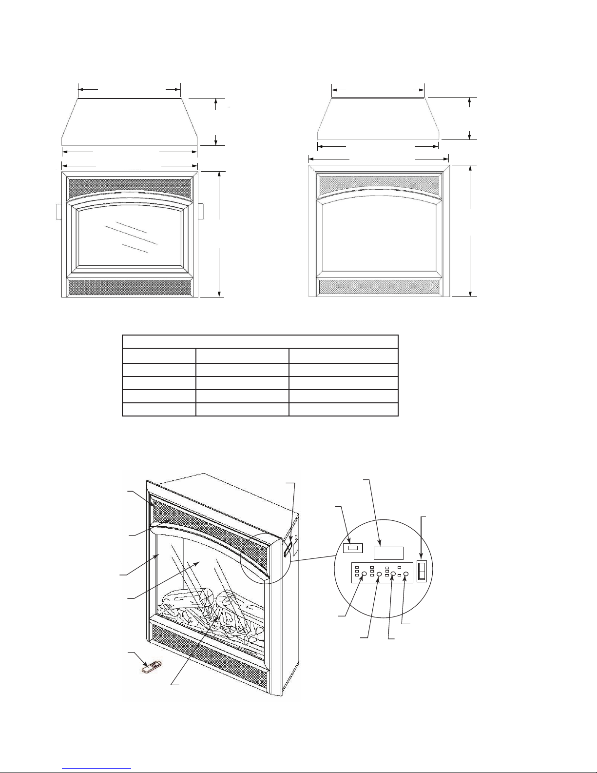
. Control panel door gets hot during heater operation. Open door by pressing on
right corner. A spring magnet will disengage. Pull door down to open.
Safety Information
Save These Instructions
WARNING: Im-
proper installation,
adjustment, altera-
tion, service or maintenance
can cause injury or property
damage. Refer to this man-
ual. For assistance or addi-
tional information, consult a
qualied installer.
CAUTION: Do not
expose the heater
to the elements
(such as rain, etc.).
— Do not place clothing or
other ammable material on
or near rebox. Never place
any objects on the replace.
— Carefully supervise young
children when they are in the
room with the replace.
— Fireplace becomes very
hot when running. Keep chil-
dren and adults away from
hot surfaces to avoid burns
or clothing ignition. Fireplace
will remain hot for a time af-
ter shutdown. Allow surfaces
to cool before touching.
— Do not install replace
directly on carpet or similar
surface which may restrict
air circulation beneath unit.
NOTE: This heater must
be electrically wired and
grounded in accordance
with local codes or, in the
absence of local codes, with
National Electric Code ANSI/
NFPA 70-latest edition or the
Canadian Electric Code,
CSA C.1 as appropriate.
This heater has been tested in accordance with the CSA Standards for xed and
location-dedicated electric room heaters in the United States. All components are UL
or CSA safety certied.

468D5301
Heater Flame Ember Backlight
Power
FP2569
WEF33 36 parts id
Installation Instructions
• WEF Fireplace Dimensions
Electrical Specications
WEF33 WEF36
Voltage 10V AC, 60 Hz 10/40V AC, 60 Hz
Total Amps 15 15 / 0
Total Watts 1500 1500 / 3000
Heater Rating 1400 Watts 800 Watts
NOTE: This heater must
be electrically wired and
grounded in accordance
with local codes or, in the
absence of local codes,
with National Electric Code
ANSI/NFPA 70-latest edi-
tion or the Canadian Elec-
tric Code, CSA C.1 as
appropriate.
• WEF Fireplace Parts Identification
Handle
Control
Panel Door
Heat Vents
(behind doors)
Front Glass
Rear Glass
(Screen)
Remote
Log Set
Magnetic
Catch
Remote Hide
ON/OFF
Power Switch
Heater
Control
Flame Control Ember Control
Backlight Control
FP569
Figure 1
Figure 2
WEF36 Shown
226M” (578 mm) 226M” (578 mm)
3356” (841 mm)
3556O” (902 mm)
10”
(254 mm)
32(6”
(835 mm)
WEF33
3756O” (953 mm)
3356” (841 mm)
10”
(254 mm)
34”
(864 mm)
WEF36
685301
WEF 33/36 dims

68D5301 5
• Locating Your Fireplace
This electric fireplace can be installed in a mantel, framed into a wall or installed
into an existing fireplace. If installing into a mantel, follow mantel's assembly instruc-
tions. Figure 3 illustrates a variety of ways the heater may be located in a room. The
heater may be installed directly on the floor or raised on a hearth.
• Unpacking and Testing
WEF33
Carefully remove unit from box. Prior to permanently installing unit, test to make sure
unit operates properly. To do this, plug unit's power cord into a conveniently located
10 Volt grounded outlet.
WEF36
Carefully remove unit from box. Prior to permanently installing unit, test to make sure
unit operates properly. Unit does not come with the power cord installed. Unit must
be hard-wired to either a 10/60 or 40/60 volt supply.
CAUTION: The unit's
power supply cord
must be connected to
a properly grounded and pro-
tected 10 Volt outlet. Always
use ground fault protection
where required by the electri-
cal code.
WARNING: Do not
operate the unit if it is
damaged or has mal-
functioned. If you suspect the
unit is damaged, return the unit
to an authorized service facil-
ity for examination, electrical
or mechanical adjustment or
repair.
WARNING: Due to
high temperatures,
this heater should
be located out of trafc. Keep
combustible materials such as
furniture, pillows, bedding, pa-
pers, clothes and curtains at
least 3 feet (914 mm) from the
front of the heater.
WARNING: Never
locate this heater
where it may fall into
a bathtub or other water con-
tainer.
NOTICE: Minimum and maxi-
mum clearances must be main-
tained at all times. Illustrations
throughout these instructions
reect typical installation and
are for design purposes only.
Actual installations may vary
slightly due to individual pref-
erences.
WARNING: To pre-
vent contact with sag-
ging or loose insula-
tion, the heater must
not be installed against vapor
barrier or exposed insulation.
Localized overheating could
occur and a re could result.
CAUTION: Do not
expose the heater to
the elements (such
as rain, etc.)
CAUTION: Wear
gloves and safety
glasses for protection
during installation and maint-
neance.
FP2388 WEF33/36
locate fireplace
3156” (791 mm)
3156” (791 mm)
44” (1118 mm)
22”
(559 mm)
Corner Mantel
Installation
Framed
into
Wall or
Existing
Fireplace
Wall Mantel
Installation
FP388
Figure 3

668D5301
• Install Fireplace
Select a suitable location that is not susceptible to moisture and is a safe distance
from drapes, furniture and high traffic areas.
NOTE: Follow all national and local electrical codes. This insert can be installed into
either an existing fireplace or as a new construction/renovation.
• Installing in a Mantel
1. Assemble mantel according to mantel instructions.
. Locate mantel near a wall (or corner depending on mantel type) close to a power
source. You may have to alter base boards to fit mantel flush against wall.
3. Insert fireplace into front of mantel. Be careful not to scratch finish on base.
Fireplace will fit flush against front of mantel.
4. Plug fireplace into power source. Push mantel with fireplace into final location.
NOTE: The MHSC Barrington Cabinet Mantel Model series BWC300, BWC400 and
BWC500 are specially designed to comply with all mantel temperature requirements.
Any custom-built mantel must comply with all clearance requirements shown in this
instruction manual.
• Existing Fireplace Installation
1. Thoroughly clean out existing fireplace and hearth area.
. Seal all drafts, vents or ash clean-outs with fiberglass insulation. Seal flue. Once
sealed, close damper to stop debris from falling onto unit.
3. If existing firebox is susceptible to moisture, cap top of chimney flue to prevent
infiltration of water.
NOTE: It is strongly advised that you hire a qualified professional to undertake this
step in order to prevent personal injury. Once flue is capped, chimney is no longer
suitable for wood burning.
NOTE: Do no install this unit into a fireplace that is prone to dampness; the area of
installation must be dry.
4. Plan the power supply. If an existing grounded outlet is near fireplace, power
cord can run along front of fireplace. If cord is not long enough to reach outlet,
a grounded extension cord minimum 14 AWG and rated to a minimum of 1875
watts, may be used. If you plan to cut or drill a hole in existing fireplace for wir-
ing, it is best to hire a professional to do this step in order to prevent personal
injury. To reduce the risk of fire, do not run power cord under rugs, carpets, etc.
Arrange power supply cord away from high traffic areas where it may pose a trip-
ping hazard.
• New Construction or Renovation
1. Select a location away from combustible materials such as curtains or drapes,
furniture, bedding, paper, etc.
. Mark desired location on floor and store unit in a safe, dry and dust free location.
3. Frame in an opening leaving at least 1/4" (6 mm) around the edge of the unit
(refer to Framing). Any new wiring must be done in compliance with local and
national codes and other applicable regulations in order to reduce the risk of fire,
electric shock or other injuries. Therefore, it is strongly recommended that you
hire a professional to complete any such work.
4. Plan your power supply route. Refer to Step 4 Existing Fireplace Installation.
WARNING - RISK
OF FIRE! The pow-
er cord must not be
pinched or against a sharp
edge. Secure cord to avoid
tripping or snagging to reduce
the risk of re, electric shock
or personal injury.
— Do not run cord under car-
peting. Do not cover cord with
throw rugs, runners or the
like. Arrange cord away from
trafc areas and where it will
not be tripped over.
WARNING - RISK
OF FIRE! To prevent
a possible re, do
not block air intake or exhaust
in any manner. Do not use on
soft surfaces where openings
may become blocked.
WARNING - RISK
OF FIRE! Do not
blow or place insu-
lation against the rebox.
WARNING: If the
information in these
instructions is not
followed exactly, a re or ex-
plosion may result causing
property damage, personal
injury or death.
— Do not store or use gaso-
line or other ammable va-
pors in the vicinity of this or
any other heater.
WARNING: The sol-
id fuel/gas replace
has been converted
for use with an electric insert
and cannot be used for origi-
nal fuels unless all original
parts have been replaced and
the replace has been reap-
proved by the authority hav-
ing jurisdiction.

68D5301 7
• Framing
Figure 4 shows a typical framing of the heater using combustible materials. All
required clearances to combustibles must be adhered to. Header height is measured
from the base of the heater.
Tools and building supplies required for installation:
• Saw • Square
• Pliers • Gloves
• Hammer • Level
• Philips screwdriver • Surround
• Framing materials • Electric drill/bits
• Tape measure
• Wall-finishing materials
• Caulking material
1056O”3456O”
3256O”
FP2570
framing
FP570
Figure 4
NOTE: The height that a com-
bustible mantel is tted above the
heater is dependent on the height
of the front selected. The minimum
height is 1" above the front.
CAUTION: Provide
adequate clear-
ances around the
air openings and adequate
accessibility clearances for
servicing and proper opera-
tions.
• Nailing Flange Installation
1. The replace has an adjustable nailing ange that will accommodate wall
installations from 1/" to 1Z\x" thick.
. Secure the nailing ange to the framing member. It is recommended to
remove the front face of the replace when nailing the ange to the wall.
Refer to the cleaning and maintenance section.
3. The nailing ange can be adjusted front to back by loosening the screw
that secures the nailing ange to the replace. Do not remove the screw
completely.
Figure 5
FP2390
mantel depth
7”
856M”
6”
12”
8”
6”
256O”
10"
4”
956O”
106M”
11”
FP390
Top of Fireplace
Opening
FP2571
nailing flange
Adjustable
Nailing Flange
FP571

868D5301
• Finishing
Combustible Finishing Material - Materials made of or surfaced with wood, com-
pressed paper, plant fibers, plastics or any material capable of igniting and burning,
whether flame proofed or not, plastered or unplastered (this includes drywall).
Noncombustible Finishing Material - Materials which will not ignite and burn. Such
materials are those consisting entirely of steel, iron, brick, tile, concrete, slate, glass
or plasters or combinations thereof or have a fire rating of zero.
• Finishing Checklist
Power supply service must be completed prior to finishing to avoid reconstruction.
Grilles and air openings cannot be covered under any circumstances.
NOTE: The heater is a zero clearance fireplace and may be finished with combus-
tible or noncombustible finishing materials.
When using paint or lacquer to finish the mantel, they must be heat resistant to pre-
vent discoloration.
WARNING: Con-
trol panel door on
this heater cannot,
in any way, be covered as it
may create a re hazard.
• WEF33 and WEF36 - 120V AC Installation
Once the site has been prepared, your fireplace can be installed.
1. Make sure power switch is in the OFF position.
. Plug fireplace into a 15-amp/10 Volt, grounded outlet. For WEF36, you will need
to purchase WEFCORD and connect to the wiring as a 10 volt AC, before plug-
ging into a 15 amp/10 volt, grounded outlet.
3. Push fireplace insert so trim is against finished mantel or wall surface.
• WEF36 - 240V AC Installation
1. Loosen the screw securing the junction box cover and remove cover.
. Complete the wiring following the wiring diagram on the box or in the homeown-
er's manual.
3. Make sure this wiring has a dedicated 0 amp fuse.
4. Place all connectors inside the fireplace and replace junction box cover.

68D5301 9
Operation
The controls are located behind the hinged control panel door. If using heater, control
panel door will be hot during and immediately after operation. Open door by pressing
on right side. A spring magnet will push door forward. Pull door down to open.
1. Plug in electric replace or if hard-wired to 40V AC, turn switch on.
. Turn on lighted power switch. Figure 6
3. Adjust Flame/Ember/Backlight/Heater to desired settings using the control pad on
replace (Figure 6) or remote control. Figure 7. Figure 8 shows replace settings
available. Default settings are circled. Press control pad or remote control buttons
once and release to adjust settings.
NOTE: When on, ember bed will lighten and darken automatically to simulate real
embers.
The heater is pre-set to the following temperatures.
• High will shut off when room reaches approximately 86°F (30°C).
• Medium will shut off when room reaches approximately 79°F (6°C).
• Low will shut off when room reaches approximately 7°F (°C).
NOTE: Fan on heater will continue to run for 5-7 seconds after heater has been
turned off.
4. When using remote control, aim remote at sensor located in center of unit just
above the log set. IMPORTANT: This remote control must remain within 0 feet (6
m) of replace to be effective.
5. When power switch is turned off, replace settings go back to default. Figure 8
Heater Flame Ember Backlight
FP2391
controls
Power
Heater Control
Flame
Control
Ember
Control
Backlight Control
Lighted Power
Switch
FP391
Figure 6
POWER
FLAME EMBER
BACKLIGHT HEATER
FP2392
Remote control
Figure 7
HEATER Off Low Medium High
FLAME Off Low Medium High
EMBER Off Low Medium High
BACKLIGHT Off Low High
Fireplace Settings
(Default settings are circled)
Figure 8

10 68D5301
Cleaning & Maintenance WARNING: Al-
ways disconnect
power and allow
the heater to cool before
performing any cleaning,
maintenance or relocation
of this heater. Turn controls
to OFF and remove plug
from outlet or turn off circuit
breaker to heater.
To service electric replace, it may be necessary to remove it from the mantel or en-
closure in which it is installed. Allow unit to cool completely before cleaning or servic-
ing.
• Cleaning Firebox
1. Open control panel door by pressing on right side. a spring magnet will push door
forward. Pull door down to open.
. Remove two () screws holding front trim in place. Pull gently to remove trim.
Figure 9. There are magnets on the lower portion of trim. Figure 9
3. With gloves and safety glasses in place, remove four (4) screws from glass re-
tainer brackets. Figure 9
4. Carefully remove front glass and brackets. Figure 10
5. Using a brush vacuum attachment, gently clean compartment.
6. After cleaning compartment, replace front glass, brackets and trim.
Trim
• Replacing Log
1. Follow Steps 1 through 4 of 'Cleaning Firebox'.
. Remove screws from each side of log securing log to sides
and remove log. Figure 11
3. Install new log using screws removed in Step .
4. Replace front glass and brackets.
5. Replace trim.
• Replacing Ember Strip
1. Follow Steps 1 and of 'Replacing Log'.
. Locate ember LED strip, Figure 11. Disconnect wire (right
side).
3. Remove ember LED strip by squeezing top of standoffs
and discard.
4. Connect new ember LED strip using existing standoffs.
5. Reconnect wire to LED strip.
FP2573
replace log

68D5301 11
6. Follow Steps 3 through 5 of 'Replacing Log'.
• Replacing Heater/Blower
1. Follow Steps 1 through 4 of 'Cleaning Firebox'.
. Remove screws from around top panel of rebox. Figure 12
3. There are several wires attached to the top panel. Carefully lift top panel.
4. Disconnect heater/blower wires from main circuit board.
5. Remove screws holding heater/blower to top panel. Figure 12
6. Remove brackets from heater/blower. Figure 13. Save brackets and screws.
7. To remove heater from blower, remove four (4) screws ( per side).
8. If replacing blower, remove screws from brackets on blower. Figure 13. Install
brackets to new blower.
9. Replace blower or heater. Replace screws removed in Step 7.
10. Hold heater/blower with brackets in place against top panel and replace screws
removed in Step 5.
11. Reconnect wires to main circuit board. Figure 15 or 16
1. Replace glass with brackets and top panel.
13. Replace trim.
FP2396
remove top panel
Screws Securing
Heater/ Blower
Top Panel
Screws
FP396
Figure 12
FP397
FP2397
remove brackets
Brackets
Figure 13
FP2398
separate blower heater
Blower
Heater
FP398
Figure 14

1 68D5301
Any electrical
re-wiring of this
appliance must be
done by a qualified elec-
trician. This wiring must
be done in accordance
with local codes and/or
in Canada with the cur-
rent CSA C22.1 Canadian
Electrical Code, and for US
installations, the National
Electrical Code ANSI/NFPA
NO 70.
If repairing or
replacing any
electrical compo-
nent or wiring, the original
wire routing, color cod-
ing and securing locations
must be followed.
Any electrical repairs or rewiring of this unit should be carried out by a licensed
electrician in accordance with national and local codes.
• Electrical Wiring Diagram - WEF33
Figure 15
WEF33 Wiring Diagram
WARNING: Disconnect Power Before Servicing
FP2574
WEF33 wiring

68D5301 13
Any electrical
re-wiring of this
appliance must be
done by a qualified elec-
trician. This wiring must
be done in accordance
with local codes and/or
in Canada with the cur-
rent CSA C22.1 Canadian
Electrical Code, and for US
installations, the National
Electrical Code ANSI/NFPA
NO 70.
If repairing or
replacing any
electrical compo-
nent or wiring, the original
wire routing, color cod-
ing and securing locations
must be followed.
Any electrical repairs or rewiring of this unit should be carried out by a licensed
electrician in accordance with national and local codes.
• Electrical Wiring Diagram - WEF36
Figure 16
WEF36 Wiring Diagram
WARNING: Disconnect Power Before Servicing
FP2575
WEF36 wiring

14 68D5301
• Replacing Transformer
1. Follow Steps 1 through 3 in 'Replacing Heater/Blower'.
. Disconnect transformer wires from control board.
3. Remove screws and nuts from rebox surround to remove
transformer. Figure 17
4. Remove and discard transformer.
5. Place new transformer against inside of rebox surround and
replace screws and nuts removed in Step 3.
6. Reconnect transformer wires to control board. Refer to Wiring
Diagram, Figure 15 or 16.
7. Replace glass with brackets, and top panel.
8. Replace trim.
• Replacing Main Control Board
1. Follow Steps 1 through 3 in 'Replacing Heater/Blower'.
. Disconnect wires to main control board.
3. Squeeze top of standoffs to remove main control board and discard.
4. Gently push new control board onto standoffs to install.
5. Reconnect wires to main control board. Refer to Wiring Diagram,
Figure 15 or 16.
6. Replace glass with brackets and top panel.
7. Replace trim.
• Replacing Backlight LED Strip
1. Follow Steps 1 and 3 in 'Replacing Heater/Blower'.
. Disconnect wires from main control board.
3. Squeeze top of standoffs to remove backlight LED strip and discard.
4. Place new backlight LED strip onto standoffs and push gently.
5. Connect wires to main control board. Refer to Wiring Diagram, Figure 15
or 16.
6. Replace glass with brackets and top panel.
• Replacing Settings Control Board
1. Follow Steps 1 through 3 in 'Replacing Heater/Blower'.
. Disconnect wires from main control board.
3. Remove screws from bracket to remove settings control board.
4. Place new settings control board into position making sure each control
is aligned with slot in panel. Install using screws from Step 3. DO NOT
overtighten. This will damage control board.
5. Reconnect wires to main control board. Refer to Wiring Diagram, Figure
15 or 16.
6. Replace glass with brackets and top panel.
7. Replace trim.
FP2400
remove transformer
Transformer
Nuts
Screws
FP400
Figure 17
FP2401
remove control board
Transformer
Main Control
Board
Standoffs
FP401
Figure 18
FP2402
replace backlight LED
Backlight
LED Strip
Standoffs
Figure 19
FP40
FP2403
replace settings cb
Screws
Settings
Control
Board
FP403
Figure 20

68D5301 15
• Replacing Flame Generation LED
1. Follow Steps 1 through 4 in 'Cleaning Firebox'.
. Remove screws securing log to either side of base. Remove log. Figure 11
3. Remove screws from sides and back of bottom panel of rebox.
4. Gently lay unit on its back.
5. There are several wires attached to bottom panel. Carefully
remove panel.
6. Disconnect wires from motor and LED drum assembly.
7. Remove screws from bottom panel to remove assembly.
8. Hold LED drum assembly in place on bottom panel and
replace screws.
9. Reattach wires to motor and LED drum. NOTE: LED drum
wires are polarity sensitive and must be connected correctly.
White wire plugs onto left terminal and red wire plugs onto
right terminal. Motor wires can be connected to either termi-
nal.
10. Replace replace bottom panel. Set replace upright and
replace screws.
11. Replace log, glass and brackets.
1. Reinstall replace and replace trim.
FP2404a
flame LED drum
White Wire
Red Wire LED Drum
Assembly
Motor
Screws
FP404a
Figure 21
• Cleaning or Replacing Rear Glass (Screen)
1. The glass is cleaned in the factory during assembly. During shipment, installation,
handling, etc., glass surface may collect dust particles. These can be removed by
bufng lightly with a clean damp cloth (water only). Glass should be completely
dried with a lint free cloth or paper towel.
. In the event of glass breakage, vacuum all remaining glass pieces with a shop
vac. DO NOT VACUUM WHILE PIECES ARE HOT. Replace glass only with
replacement part specically for this heater. Never substitute material. Only fully
tempered soda lime safety glass may be used on this heater.
3. To access glass to clean or replace, follow Steps 1 and 7 in 'Replacing Flame
Generation LED'. Set aside bottom panel.
4. Using gloves, gently remove glass panel by sliding it toward you. There is a rub-
ber bumper on each corner of glass.
5. Clean glass as instructed in Step 1 or replace glass.
6. Using gloves, reinstall glass by gently sliding, smooth side toward replace front,
into brackets on either side that hold glass in place.
7. Replace log base.
8. Follow Steps 11 and 14 in 'Replacing Flame Generation LED'.

16 68D5301
Troubleshooting
WARNING: Turn
off appliance and
allow to cool before
servicing. Only a qualied
service person should ser-
vice and repair heater.
Problem
1. Fireplace turns off
and will not turn
on.
. Flame is not mov-
ing.
3. Flame is not vis-
ible.
4. Log set and/or em-
ber is not glowing.
5. Flame sputters/
ashes.
6. Remote control
does not work.
7. Fireplace will not
come on when
switch is ipped to
ON.
8. Heater does not
provide heat when
turned on.
Possible Cause
1. Fireplace has overheated
and safety devise has caused
thermal switch to disconnect
or home circuit breaker has
opened.
1. Loose wiring.
. Flame motor defective.
1. Wiring is loose.
1. Wiring is loose.
1. Flame motor is defective.
. Flame generation contacts
dirty/obstructed.
1. Low batteries.
. Not aiming control correctly.
3. Defective remote control and
/or sensor.
1. Fireplace is not plugged in to
an electrical outlet.
. Control failure.
3. Breaker tripped.
1. Thermal switch has been
tripped.
. Circuit breaker has been
tripped.
3. Wiring is loose.
4. Heater is defective.
5. Thermostat cycled off.
Solution
1. Reset switch by turning main
power switch off and waiting 5
minutes then turning it back on
or reset circuit breaker.
1. Inspect wiring for loose con-
nections.
. Call a qualied service techni-
cian to replace ame motor.
1. Disconnect from power source
and inspect wiring for loose
connections and repair or
replace if necessary.
1. Disconnect from power source
and inspect wiring for loose
connections and repair or
replace if necessary.
1. Call a qualied service techni-
cian to replace ame motor.
. Disconnect power. Follow
steps to replace ame genera-
tion LED. Clean contacts with
dry cloth.
1. Replace AAA batteries in
remote control.
. Aim control at sensor located
directly behind glass screen in
center of unit just above logs.
3. Replace remote control and/or
sensor.
1. Check plug.
. Call a qualied service techni-
cian.
3. Reset breaker.
1. Turn unit off and unplug unit
for 5 minutes. Plug back in and
turn unit on. If plug cannot be
reached, follow directions for
tripped circuit breaker.
. Turn off circuit breaker that
supplies electricity to unit.
Wait 5 minutes then ip circuit
breaker back on.
3. Disconnect from power source
and inspect wiring for loose
connections and repair or
replace if necessary.
4. Replace heater.
5. Change to higher setting.

68D5301 17
WEF33, WEF36 Electric Fireplace
MHSC reserves the right to make changes in design, materials, specifications, prices and discontinue colors and products at any time, without
notice.
Ref. Description Qty. WEF33 WEF36
1. Blower (Motor and Fan) 1 68D5101 68D501
. Rear Glass (Screen) 1 68D50 68D50
3. Log Set 1 68D503 68D503
4. Flame Effect Mirror 1 68D504 68D504
5. Handles 68D5105 68D5105
6. Main Control Board and Standoffs (5) 1 68D5106 68D506
7. Transformer 1 68D5107 68D507
8. Heater 1 68D5108 68D508
Replacement Parts

18 68D5301
WEF33, WEF36 Electric Fireplace
9. Settings Control Board 1 68D5109 68D5109
10. LED Drum Assembly 1 68D510 68D510
11. LED Ember Strip 1 68D5111 68D5111
1. Remote Control 1 68D511 68D511
13. Remote Control Sensor 1 68D5113 68D5113
14. Power Cord 1 68D5114 --
15. ON/OFF Switch 1 68D5115 68D51
16. Front Glass 1 68D516 68D516
17. Control Panel Door (black) 1 68D56 68D517
18. Top (black) 1 68D518 68D513
19. Front Trim 1 68D519 68D515
0. Magnetic Catch 1 68D510 68D510
1. LED Back Light 1 68D55 68D55
. Nailing Flange Bracket 68D514 68D50
Parts Available - not shown
Wire - LED Drum Motor 1 68D51 68D51
Wire - LED Drum Lighting 1 68D5 68D5
Wire - Ember Bed 1 68D53 68D53
Wire - Back Light 1 68D54 68D54
Thermocouple 1 68D515 68D515
Ref. Description Qty. WEF33 WEF36

68D5301 19
WARRANTY
BASIC WARRANTY
MHSC warrants the components and materials in your electric replace to be free from manufacturing
and material defects for a period of one year from date of installation. After installation, if any of the
components manufactured by MHSC in the electric replace are found to be defective in materials or
workmanship, MHSC will, at its option, replace or repair the defective components at no charge to the
original owner. MHSC will also pay for reasonable labor costs incurred in replacing or repairing such
components for a period of one year from the date of installation.
Any products presented for warranty repair must be accompanied by a dated proof of purchase.
This warranty will be void if the electric replace is not installed by a qualied installer in accordance
with the installation instructions. The warranty will also be void if the electric replace is not operated
and maintained according to the operating instructions supplied with the electric replace, and does not
extend to 1. damage by accident, neglect, misuse, abuse, alteration, negligence of others, including the
installation thereof by unqualied installers , the costs of removal, reinstallation or transportation of
defective parts on the electric replace, or 3. incidental or consequential damage. All service work must
be performed by an authorized service representative.
This warranty is expressly in lieu of other warranties, express or implied, including the warranty of mer-
chantability of tness for purpose and of all other obligations or liabilities. MHSC does not assume for
it any other obligations or liability in connection with the sale or use of the electric replace. In states
that do not allow limitations on how long an implied warranty lasts, or do not allow exclusion of indirect
damage, those limitations of exclusions may not apply to you. You may also have additional rights not
covered in this warranty.
MHSC reserves the right to investigate any and all claims against the Limited Lifetime Warranty and
decide upon method of settlement.
IF WARRANTY SERVICE IS NEEDED...
1. Contact your supplier. Make sure you have your warranty, your sales receipt and the model/serial
number of your MHSC product.
. DO NOT ATTEMPT TO DO ANY SERVICE WORK YOURSELF.

0 68D5301
MHSC
149 Cleveland Drive • Paris, Kentucky 40361
www.mhsc.com
This manual suits for next models
1
Table of contents
Other MHSC Indoor Fireplace manuals
Popular Indoor Fireplace manuals by other brands

Faber
Faber Odense installation manual

Enviro
Enviro E441 owner's manual

Jøtul
Jøtul GI 350 DV Installation and operation instructions

HOMCOM
HOMCOM 820-090V01 manual

White Mountain Hearth
White Mountain Hearth Morgan Creek LS-30MC-1 Installation instructions and owner's manual

Heatiator
Heatiator SC60 owner's manual

LOHBERGER
LOHBERGER COOK ME Operating manual with installation instructions

Comfort Smart
Comfort Smart CS-35-WL operating manual

Sievert
Sievert Promatic 3366 Directions for using

Superior
Superior B-500CEN Homeowner's care and operation instructions

Twin-Star International
Twin-Star International 34HF600GRA manual

komodo
komodo SP5733 user manual