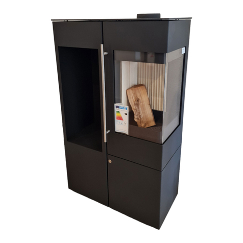
Mi-Fires Coniston Inset User manual

Installation and
Operation Manual
Version_1_01_2023_Coniston
www.mi-flues.com
BS EN 13229:2001 + A2:2004
Tested as intermittent appliance
burning wood logs & solid fuel
MODEL:
Coniston Inset

2
Before we start
Thank you and congratulations, you are now the proud owner of one
of the most environmentally friendly and efficient multifuel burning
stoves available on the market today.
Your new stove is fully compliant with all European and UK laws and meets all the criteria of EcoDesign
2022.
Please take a moment to study some of the key points that should be taken into consideration before
you start using your new stove.
At Mi-Fires, we believe the best way to enjoy the maximum benefit from your new stove is that it should
be installed by a fully trained competent stove installer that can identify the optimal way to install and
commission your new appliance.
You can find a list of fully approved and trained stove and chimney installers on the HETAS website or
take advice from a registered competent person.
WWW.HETAS.CO.UK
Please Note: It is a legal requirement under England, Scotland, N.I. and Wales building regulations that
the installation of the stove is carried out under local authority building control approval or installed by
a competent person registered with a government approved scheme.
MI-Fires are CE, UKCA, UKNI approved, Defra smoke exempt and can be used in smoke controlled zones
only when the stop is in place and installed in accordance with the current building control regulations.
An approved Carbon Monoxide monitor must be installed in the same room as the appliance, with a
battery that lasts the lifetime of the product.
Please note: this is a Multi-fuel stove, your new stove has been specifically designed for the
combustion of wood <20% Moisture and approved wood bricks. The use of approved manufactured
Smokeless mineral fuels is also allowed.
The appliance should not be used as an incinerator for house hold waste or any unapproved fuels.
This appliance does get hot whilst running. It is recommended that a suitable guard is used to protect
children and the elderly or infirm.
Please do not make any unauthorised changes or modifications to your appliance.
Warning: Take care, the stove surfaces reach extremely high temperatures. To minimise the
effects to the environment a few keys rules should be remembered.
Always Ensure:
The Correct Stove
The Correct Installation
The Correct Fuel
The Correct Operation
The Correct Sweeping and Maintenance
These few rules when followed will give you years of heat and enjoyment from your new stove.
PRODUCTION NUMBER
The stove has a production number on the rating plate on the back of the stove.
We recommend that you note down this number in the box below before mounting the stove.
For the purposes of the guarantee and for other enquiries, it is important that you are able to quote this
number.
PRODUCTION NUMBER:

3
Coniston Inset
CONTENTS
1. COMPLIANCE
1.1 Technical Data . . . . . . . . . . . . . . . . . . . . . . . . . . . . . . . . . . . . . . . . . . . . . . . . . . . . . . . . . . . . . . . . . . . . . 4
2. INSTALLATION OF THE STOVE
2.1 Pre-Installation .....................................................................5
2.2 Position of the stove / Distance Requirements .....................................5
2.3 Preparation of the fire for installation ............................................. 6
2.4 Flue Requirements .................................................................7
2.5 Ventilation / fresh air supply ........................................................7
2.6 The Clean Air Act 1993 and smoke control areas....................................7
2.7 Commissioning .................................................................... 8
3. LIGHTING AND USING THE STOVE
3.1 Important safety information...................................................... 8
3.2 The first time a fire is lit ............................................................ 8
3.3 The Stove Air Controls ............................................................. 8
3.4 How should I use my wood burning stove? ....................................... 9
3.5 Lighting a fire in the wood burning stove ......................................... 9
3.6 Important Information for wood burning ......................................... 9
3.7 Lighting a fire using smokeless fuel ...............................................10
3.8 Important Information for burning smokeless fuel ...............................10
4. CLEANING AND MAINTENANCE
4.1 Chimney Sweeping ................................................................10
4.2 Combustion chamber .............................................................11
4.3 Glass ...............................................................................11
4.4 Gaskets ............................................................................11
4.5 Ash .................................................................................11
4.6 Cleaning the stove .................................................................11
4.7 Spare Parts List ....................................................................11
5. WARRANTY & RECORDING
5.1 MI-Fires Stoves Warranty . . . . . . . . . . . . . . . . . . . . . . . . . . . . . . . . . . . . . . . . . . . . . . . . . . . . . . . . . . 11
5.2 Installer details and Handover checklist...........................................12
5.3 Annual Service / Sweeping record.................................................13
5.4 Warranty Registration . . . . . . . . . . . . . . . . . . . . . . . . . . . . . . . . . . . . . . . . . . . . . . . . . . . . . . . . . . . . .14

4
1. COMPLIANCE
1.1 TECHNICAL DATA
This appliance designed for intermittent operation only
Maximum log length 270mm x 100mm width
Item No. MI-Fire Coniston Inset
Weight 70KGS
Dimensions (WxDxH mm) Four Sided 552 x 431 (Max Footprint excl Handle) x 683
Three Sided 552 x 431 (Max Footprint excl Handle) x 613
Inset 399 x 358 x 549
Flue size 125mm
WOOD LOGS
PARAMETER
Total efficiency 83.7%
Nominal heat output 5.0kW
Mean CO2 emission 12.10%
Mean CO emission 0.13%
Mean CO emission
(at 13 % O2) 0.09%
Mean flue gas temperature 258ºC
Flue gas mass flow 3.4 g/s
Mean CnHm emission
(at 13 % O2) 65 Nmg/m3
Mean NOx emission
(at 13 % O2) 76 Nmg/m3
DIN Plus particulates
(at 13 % O2) 22 Nmg/m3
MINERAL SMOKELESS FUELS
PARAMETER
Total efficiency 82.5%
Nominal heat output 5.3 kW
Mean CO2 emission 11.11%
Mean CO emission 0.13%
Mean CO emission
(at 13 % O2) 0.08%
Mean flue gas temperature 258ºC
Flue gas mass flow 3.4 g/s
Mean CnHm emission
(at 13 % O2) 65 Nmg/m3
Mean NOx emission
(at 13 % O2) 76 Nmg/m3
DIN Plus particulates
(at 13 % O2) 39 Nmg/m3
Please note that details and specifications contained herein are correct at the time of going to print. We
reserve the right to change specifications at any time without prior notice.
1.3 TRANSPORTATION
When taking your multifuel stove home, please
ensure that it travels in an upright position.
If you wish to lay it flat, it is important that you
remove all loose parts from the combustion
chamber.
Your new multifuel stove is optimally protected
against damage by the packaging. However,
damages to the stove or accessories may have
occurred during the transport despite this.
For this reason, it is necessary to check your
multifuel stove for damages and completeness
after unpacking!
Immediately report any defects to your specialist
stove dealer!
Note: This appliance is heavy and must be
handled with care. Adequate facilities must
be available for loading, unloading and site
handling.

5
2. INSTALLATION OF THE STOVE
2.1 PREINSTALLATION
It is a legal requirement under England and Wales
building regulations that the installation of the
stove is carried out under local authority building
control approval or installed by a competent
person registered with a government approved
scheme.
It is important to ensure that all local rules and
regulations, including ones relating to national
and European standards, are complied with when
installing this device.
Your dealer can also provide you with installation
advice. Remember, it is your responsibility that
rules in force are complied with.
More information can be found out by consulting:
British Standards BS 8303. BS EN 15287-1:2010
Building Regulation Approved Document J for
England and Wales
Building Regulations Part F for Scotland
Building Regulations/1997 Technical Guidance
Approved
Document J-Heat Producing Appliances for
the Republic of Ireland
Registered Body: HETAS (GB only) INFO
(Ireland)
Health and Safety Precautions: Special care must
be taken when installing the stove such that the
requirements of the Health and Safety at Work
Act are met.
2.2 POSITION OF THE STOVE DISTANCE
REQUIREMENTS
The appliance must stand on a non-combustible
constructional hearth which is at least 125mm
thick with the minimum dimensions as shown
in the diagram below (please refer to Building
regulations Documents J for further information)
If the appliance is being installed in a raised
position, due consideration should be given to
extending the depth of the superimposed hearth
to safely contain any falling embers or logs.
The hearth and building construction must be of
suitable material to comply with current building
and local authority regulations. The fabrication
of the construction must have a suitable load
bearing capacity for the appliance and hearth.
If in doubt, please contact a competent person for
advice before proceeding
THE BUILDERS OPENING
For ease of installation the builders opening
may be made slightly larger than the appliance
dimensions.
A typical size builders opening would be 420mm
wide X 580mm high X 370mm Deep
The construction of the fireplace recess should
be of a suitable non-combustible material such as
brick or concrete blockwork, and have a minimum
thickness of 200mm to the sides and rear of the
appliance, unless it is a back to back recess with
another property.
Please refer to Building regulations document J
for further information.
CLEARANCES TO COMBUSTIBLE
MATERIALS
Installation into a false chimney breast
All parts of the false studwork chimney must be
constructed of a non-combustible material such
as metal studwork.
Do not use combustible materials within the
white area (250mm to the sides and rear of the
appliance)
250mm 250mm
250mm

6
Do not fill the area surrounding the appliance
with insulating material, the void around the
appliance must be ventilated to prevent the
build-up of excess heat.
There must be a minimum ventilating area at
both high and low levels of 50cmeach, the vents
should take ambient air from the room in which
the appliance is installed and return the warm air
back into the same room environment.
Consideration should also be taken to provide
adequate access to the connecting flue for
servicing and maintenance purposes.
Installation into a wooden decorative fireplace
If the appliance is to be installed in conjunction
with a combustible fire surround the minimum
clearances shown in the diagram must be
maintained.
2.3 PREPARATION OF THE FIRE FOR
INSTALLATION
Remove internal components as follows and put
to one side
a) Remove ash pan
b) Lift and remove log retaining bar
c) Lift and support vermiculite baffle whilst
removing left side vermiculite panel
d) Keep vermiculite baffle supported whilst
removing right side vermiculite panel
e) Lower vermiculite baffle and remove from
firebox
f) Remove both rear vermiculite panels
g) Lift and remove fuel grate
h) Release the two screws securing the upper
metal baffle, slide out and remove baffle
i) Release the four screws holding the flue
spigot, rotate the spigot a few degrees and
remove
j) Remove the two screws located in each side of
the firebox.
The firebox will now slide away from the outer
casing.
At this point determine whether the stove is to be
installed as a three sided model sat on a hearth,
if so remove the two upper screws holding the
lower fascia bar in position
Prepare your flue liner with either a long tail MA
adapter, or a standard MA adapter and a short
length of vitreous connecting pipe (250mm)
which can be angled to ease connection if
required.
Install the outer casing into your prepared
opening and secure to the wall / fireplace using
suitable mechanical fixings. This can be executed
by drilling through either the flange into the wall,
or the base into the hearth.
Lift the stove into the external casing and secure
with the two side firebox screws. Due to the
weight of the stove, it is recommended that this
is a two person operation.
Lower the connecting pipe into the stove, offer up
the flue spigot and secure to the connecting pipe,
push the flue liner upwards and secure the spigot
using the four location bolts.
Replace the internal components in reverse order
ensuring the metal baffle is correctly located.
The dimensions must be adhered to from any
point of the appliance to any combustible
material.
Minimum front distance to combustibles is
1200mm.
If stone, marble, granite or any other non-
combustible decorative material is to be used as
a superimposed hearth or back panel, provision
should be made to allow for heat expansion. The
use of a split and slabbed back panel and hearth
is recommended.
If in doubt please seek the advice of a competent
person.
Curtains and soft furnishings should be kept a
minimum of 1 metre away from the appliance. We
do not recommend that televisions or expensive
artwork are hung above the fireplace.
250mm 250mm
500mm

7
2.4 FLUE REQUIREMENTS
Please ensure that all local rules and regulations
are complied with, including CE marking of the
flue pipe. Additionally, distance requirements
to flammable material for the pipe must be
respected.
It is important that there is sufficient draw in
the chimney and that the chimney does not
suffer from down-draught. When the chimney is
warm the draw should be not less than 1.25mm
(0.05 inches) water gauge (12.pa). There are many
factors that affect the chimney draft, including
the outside temperature, wind strength, and
surrounding buildings. The minimum flue height
requirement is 4.0 metres, if this cannot be
achieved you will have to seek the advice of a flue
and chimney specialist to carry out a BS EN13384
Chimney Calculation to see if the chimney will
work.
If the stove is being fitted into a brick chimney or
clay / concrete chimney it must be swept before
installation and checked for soundness and
suitability.
The chimney must also be free from cracks and
blockages. We advise you take the advice of a
registered chimney sweep on this matter.
In all cases we recommend the use of a stainless
steel MI-Flex liner when retro fitting into an
existing fire place, as this will help give you the
optimal flue draft required to operate your stove
correctly.
If the stove is fitted in place of an open fire and no
flue liner is fitted then provision should be made
to clean the entire length of the chimney without
removing the appliance and the chimney should
be swept one month after installation to clear any
soot falls which may have occurred.
The connection to the existing chimney can be
made with CE marked BS EN 1856-2 connecting
pipe made from vitreous enamel or 316 stainless
steel with a minimum thickness of 0.6mm.
If no chimney is present the use of an EN1856-part
1 chimney system is required. Example: MI-Flues
TWPro.
The chimney and connecting flue pipe must not
narrow to less than the size of the outlet socket of
the stove at any point.
This appliance must not be used in a shared flue
system.
The minimum flue draft is 12 Pascal’s at nominal
output.
2.5 VENTILATION FRESH AIR SUPPLY
In order for the multifuel stove to function
at optimum efficiency, air is needed for the
combustion process. There must be sufficient
fresh air coming into the room containing the
wood burning stove.
In very well-insulated houses, or houses with
powerful cooker hoods and/or air conditioning
systems, a vacuum can be created around the
multifuel stove, leading to smoke leakage and
poor combustion.
In normal scenarios this stove complies with the
guidance given in approved Document J of the
Building Regulations that states that purpose
provided ventilation is not required in England
and Wales unless the appliance nominal rated
output is greater than 5kW.
Extractor Fan Warning: There must not be an
extractor fan fitted in the same room as the stove
as this can cause the stove to emit fumes into
the room. If unavoidable the appliance must be
checked with Approved Document (A.D.) 1.21 and
necessary action taken
Action may have to be taken if other heating
appliances are in the same dwelling to make sure
the correct ventilation applies.
2.6 THE CLEAN AIR ACT 1993 AND SMOKE
CONTROL AREAS
Under the Clean Air Act local authorities may
declare the whole or part of the district of the
authority to be a smoke control area.
It is an offence to emit smoke from a chimney of
a building, from a furnace or from any fixed boiler
if located in a designated smoke control area. It is
also an offence to acquire an “unauthorised fuel”
for use within a smoke control area unless it is
used in an “exempt” appliance (“exempted” from
the controls which generally apply in the smoke
control area).
In England appliances are exempted by
publication on a list by the Secretary of State in
accordance with changes made to sections 20
and 21 of the Clean Air Act 1993 by section 15 of
the Deregulation Act 2015.
In Scotland appliances are exempted by
publication on a list by Scottish Ministers under
section 50 of the Regulatory Reform (Scotland)
Act 2014.
In Northern Ireland appliances are exempted
by publication on a list by the Department of

8
Agriculture, Environment and Rural Affairs
under Section 16 of the Environmental Better
regulation Act (Northern Ireland) 2016.
In Wales appliances are exempted by regulations
made by Welsh Ministers.
Further information on the requirements of the
Clean Air Act can be found here:
www.gov.uk/smoke-control-area-rules
Your local authority is responsible for
implementing the Clean Air Act 1993 including
designation and supervision of smoke control
areas and you can contact them for details of
Clean Air Act requirements.
The Mi-Fires Coniston Inset has been
recommended as suitable for use in smoke
control areas when burning wood logs. The
appliance has been fitted with a modification
to fix the air controls at the correct minimum
position to comply with the smoke control
requirements.
All MI-Fires stoves are factory fitted with the
Smoke control modification in place.
2.7 COMMISSIONING
Check all internal parts are fitted correctly and there
are no gaps between the firebricks and baffles
and the log retainer is secure. Make sure the flue
connection if secure and sealed.
Check all the levers are operating fully and freely.
Carbon Monoxide Alarm: Building Regulations
require that whenever a new or replacement fixed
solid fuel or wood/biomass appliance is installed in a
dwelling a carbon monoxide alarm must be fitted in
the same room as the appliance.
Further guidance is available in BS EN50292:2002
and from the alarm manufacturer’s instructions.
Provision of an alarm must not be considered a
substitute for either.
3. LIGHTING AND USING THE STOVE
3.1 IMPORTANT SAFETY INFORMATION
The stove will become warm during use and
therefore it should be treated with all necessary
caution.
Never keep easily combustible fluids such as
petrol in the vicinity of the multi fuel stove.
Never use easily combustible fluids to light the
fire in the wood burning stove.
Never empty the ashes when the multi fuel
stove is warm. Embers may still be found in the
ash for up to 24 hours after the fire has gone out.
Please wait to empty the ash until you are sure
that there are no embers in the ash.
The door should be kept closed while the multi
fuel stove is in use. While lighting the fire, the
door can stand ajar for the first few minutes.
In the event of a chimney fire: Close both air
controls on the stove and call the fire-fighting
service.
Your installer should have fitted a Carbon
Monoxide alarm in the same room as the
appliance. If the alarm sounds unexpectedly,
leave the premises immediately and contact
installer. Let the fire go out.
The control and handles will get warm when the
multi fuel stove is in use. Please use the glove or
tool provided when you operate the multi fuel
stove.
3.2 THE FIRST TIME A FIRE IS LIT
The first few times the stove is used, there may
be some smoke and unpleasant odours from
the multi fuel stove, which is fairly normal. This
is caused by the heat-resistant paint hardening.
Make sure there is sufficient ventilation during this
stage.
It is also important not to let the fire burn too
fiercely the first 2-3 times, so that the multifuel
stove has time to expand slowly.
You should also be aware that the stove may make
some clicking sounds as it heats up and cools
down - like pouring boiling water into a sink. These
are caused by the great differences in temperature
to which the materials are being exposed.
During the first firing, which should be carried
out using approximately 1 kg of wood, the
stoking door must be left slightly open and
must not be closed until the stove is cold. This is
to prevent the sealing rope sticking to the stove.
3.3 THE STOVE AIR CONTROLS
The amount of heat emitted by the stove is
regulated using the air controls built into the front
of the stove.
When using wood after the stove has reached
operating temperature the stove is controlled by
closing the primary air and adjusting the output
and flame effect with the secondary air control.
When using manufactured mineral fuels after
the stove has reached operating temperature the
stove is controlled by reducing the secondary air
control and adjusting the primary air control to
gain the required heat output and flame effect.

9
AIR CONTROLS LEFT OPEN. Operation with
the air control open can cause excess smoke.
The appliance must not be operated with air
controls, or door left open except as directed in
the instructions.
3.4 HOW SHOULD I USE MY STOVE WHEN
WOOD BURNING?
The multifuel stove is intended for intermittent
combustion. This means that each stoking should
burn down to embers before new logs are added.
To obtain the best possible combustion, you should
regulate the effect/heat output with the fuel and
air. Burning small logs provides more powerful
combustion than burning large logs as the surface
area is greater and more gas is released.
The amount of wood in the combustion chamber
is another factor that affects combustion. The
optimum combustion is achieved by placing two
logs in the stove. If you want an enhanced effect,
you can add more logs.
The ideal heat output is reached by burning
approx. 1.5 kg per hour.
3.5 LIGHTING A FIRE WHEN USING WOOD
The fire lighting method is very important for
starting combustion quickly and efficiently.
1. Open both air controls fully.
2. Place two small logs sideways on the grate
and place several sticks of kindling at an angle
upon them in a cross hatch shape. Place some
firelighters on top of the kindling and light with
a match.
3. Keep the door approx. 1 cm ajar. When there are
distinct visible flames from the kindling, and the
fire has taken hold, then close the door.
Warning: The control and handles will get warm
when the wood burning stove is in use. Please
use the glove or tool provided when you operate
the wood burning stove.
4. Once the first charge of wood has burnt away
leaving a glowing bed of embers you should be
able to shut off the primary air controls. Slowly
open the stove door using the glove provided
and re-stoke the fire with the desired amount of
wood. Close the door and open the secondary
air control to maximum for a few minutes to
allow the new wood to catch fire then slowly
push the air control back into the stove until the
desired effect is reached.
In order to avoid the quenching of the stove fire by
use of oversized logs we recommend a maximum
wood fuel size of 4” (10cm) diameter by 10” (27cm)
length split seasoned logs, with a maximum
moisture content of 20%.
This appliance is designed to operate with the door
closed, except for lighting and reloading, failure to
close the door during operation can result in fume
spillage.
Warning: Properly installed, operated and
maintained this appliance will not emit fumes into
the dwelling.
Occasional fumes from re-fuelling may occur.
However, persistent fume emission is potentially
dangerous and must not be tolerated. If fume
emission does persist, the following immediate
actions should be taken:
Open doors and windows to ventilate room then
leave the premises. Let the fire go out or eject and
safely dispose of fuel from the appliance.
Check for flue or chimney blockage, and clean if
required. Do not attempt to relight the fire until the
cause of the fume emission has been identified
and corrected. If necessary seek expert advice
3.6 IMPORTANT INFORMATION FOR
WOOD BURNING
With a full load of wood and burning near
nominal output the stove will need to be refuelled
approximately every 1-1.5 hours. One or two large
logs will burn longer than a number of smaller ones.
Care must be taken that logs do not touch the baffle
or the glass panel. Do not stack logs above the level
of the tertiary air inlet holes at the back of the stove.
Secondary
Air Control
Primary
Air Control

10
Always make sure that flames are visible above
the wood after re-fuelling for cleanest burning.
Burning without flames above the fuel will create
unnecessary smoke. After re-fuelling open the
primary air control fully for 3 minutes or until the
logs are fully blackened to achieve full flames above
the fuel.
Wood burns best on a bed of ash and it is therefore
only necessary to remove surplus ash from the stove
occasionally. Burn only dry, well-seasoned wood,
which should have been cut, split and stacked -
under cover from rain - for at least 12-24 months with
free air movement around the sides of the stack to
enable it to dry out.
Burning wet or unseasoned wood will create tar
deposits in the stove and chimney and will not
produce a satisfactory heat output. Wood that is not
properly dry (‘dry’ is considered to be less than 20%
internal moisture content) uses up energy from the
burn process to evaporate the water inside the wood
thus creating very poor conditions for combustion.
The main cause of burning problems with wood
stoves is due to excessively damp wood. Wood can
appear perfectly dry on the outside but still contain
40-50% water on the inside. A moisture meter can
be purchased from stove and equipment suppliers if
you wish to check your wood source is correct. Split
a log and check the inside as well as the outside.
Refuelling on to a low fire bed if there is insufficient
burning material in the fire bed to light a new
fuel charge, excessive smoke emission can occur.
Refuelling must be carried out onto a sufficient
quantity of glowing embers and ash so that the new
fuel charge will ignite in a reasonable period. If there
are too few embers in the fire bed, add suitable
kindling to prevent excessive smoke.
Fuel overloading the maximum amount of fuel
specified in this manual should not be exceeded,
overloading can cause excess smoke.
Operation with door left open Operation with the
door open can cause excess smoke and spillage into
the room. The appliance ‘Must Not’ be operated
with the appliance door left open.
3.7 LIGHTING A FIRE USING SMOKELESS
FUEL
■ Pull open both air control fully.
■ Lay firelighters on the grate and add a small
amount of kindling wood to the top.
■ Place a small quantity of smokeless fuel on top.
■ Light firelighters safely using matches leave the
door slightly open.
■ When the fire is fully established add more
smokeless fuel and close the door.
■ After another five to ten minutes close the
secondary air by sliding inward the left side
control.
■ The output and flame effect can be altered by
opening and closing the primary (right side) air
control lever.
Care should be taken to ensure that the firebox is
not overfilled with smokeless fuel – it should be no
higher than the log retaining bar.
3.8 IMPORTANT INFORMATION FOR
BURNING SMOKELESS FUEL
When re-fuelling the stove always refuel onto a bed
of hot embers, fully open the secondary and primary
air controls until the new fuel is well alight, before
adjusting the air controls for the desired setting. If
there is insufficient burning material in the fire-bed
to light a new fuel charge, excessive smoke emission
can occur.
Re-fuelling must be carried out onto a sufficient
quantity of glowing embers and ash that the new
fuel charge will ignite in a reasonable period. If there
are too few embers in the fire bed, add suitable
kindling to prevent excessive smoke.
Fuel overloading, never overload the stove. The
amount of fuel specified in this manual should not
be exceeded, overloading can cause excess smoke.
Operation with door left open can cause excess
smoke. The appliance must not be operated with
the appliance door left open except as directed in
the instructions.
Never leave the stove unattended until the new fuel
is well alight. Persistent fume emission is dangerous
and must be investigated. If fume emission persists,
open doors and windows to ventilate the room and
let the fire dies out. Have the chimney inspected for
blockages and clean if required. Do not relight the
fire until the cause has been found. We recommend
that you seek professional advice.
This appliance has been designed to be burned
with the door closed at all times other than when re-
fuelling. It should not be operated as an open fire.
Typical re-fuelling for smokeless fuel is 2 hours.
Daily Maintenance The ash pan should be checked
and emptied regularly. You should never allow the
ashes in the pan to build up to the level of the grate.
If they are allowed to build up, the grate will become
sandwiched between the ash below it and above it.
This will overheat the grate and cause distortion and
premature wear.

11
4. CLEANING AND MAINTENANCE
4.1 CHIMNEY SWEEPING
Ensure your stove and chimney is swept at least
once a year by a professional accredited chimney
sweep. Use the HETAS find a chimney sweep tool.
www.hetas.co.uk/find-chimney-sweep/
The top baffle must also be cleaned once a year at
least to remove any build-up of ash or residue from
the chimney.
4.2 COMBUSTION CHAMBER
The fireproof tiles in the combustion chamber
eventually wear out and should be replaced when
the cracks are more than 0.5 cm. The durability of
the tiles depends on how often and how intensively
the stove is used.
Spare parts are available from MI-Fires directly or
from your local Mi-Fires dealer.
4.3 GLASS
Wet wood, unsatisfactory chimney draft, and wrong
use of the stove can leave soot stains on the glass
pane. They can easily be removed using a damp
cloth that you dip in cold ash and rub on the sooty
glass.
Special cleaning agents are also available to remove
soot from glass, e.g. the Trollull Stove Glass Cleaner.
The pad neither scratches or damages the glass
and is for multiple usages. Water or other cleaning
agents are not necessary.
It is common maintenance to tighten the glass
fittings shortly after the stove has been installed as
well as to check if the gaskets are properly placed.
4.4 GASKETS
With time, gaskets around glass and door will wear.
We recommend that you inspect them regularly. If
leakages appear, they must be replaced.
4.5 ASH
The ash pan should be checked and emptied
regularly. You should never allow the ashes in the
pan to build up to the level of the grate.
If they are allowed to build up, the grate will become
sandwiched between the ash below it and above it.
This will overheat the grate and cause distortion and
premature wear.
4.6 CLEANING THE STOVE
The stove’s surface is treated with a heat-resistant
Senotherm® paint, which will stay at its best just
by being vacuumed with a small, soft mouthpiece
or dusted with a soft, dry cloth. Do not use spirit or
other solvents, as they will remove the paint.
MI-Fire stoves are painted with a heat-resistant paint
that can withstand temperatures up to 500 degrees.
If the surface of the stove gets scratched or worn, it
can easily be renewed using this type of paint. The
paint is available in black metallic from your local
dealer.
4.7 SPARE PARTS LIST
All spare parts and consumable items are available
directly from MI-Fires or can be purchased from
your local stove specialist.
5. WARRANTY & RECORDING
5.1 MIFIRES STOVES WARRANTY
Terms & Conditions
The Firebox of your MI-Fires Stove is Guaranteed
against manufacturing and material defects for
a minimum period of 12 months from the date of
purchase, you can however extend the warranty
period in a number of ways.
■ Completing and returning the warranty
registration form will increase the warranty to two
years*
■ Installing the stove with an “MI-Flues” flue liner or
chimney system can extend the warranty to ten
years**
The Warranty commences on the date of purchase.
This warranty will only cover consumable parts if the
purchaser can prove that they were damaged upon
receipt of the stove.
The warranty is non-transferable and is only
available to the original purchaser.
This warranty does not affect your statutory rights.
In the unlikely event of any failure we will replace any
defective part free of charge, labour cost excluded.
The Stove and Flue system must be inspected,
serviced and cleaned on an annual basis by a
suitably qualified engineer, certificates and receipts
must be retained as proof of maintenance.
EXCLUSIONS & LIMITATIONS
The warranty will be void if the appliance is not
installed by a suitably qualified person, or is not
installed in accordance with the current building
regulations.
The warranty will be void if the appliance is modified
in any way or assembled incorrectly.
MI-Flues Ltd will not be responsible for any
incidental or consequential loss, damage or injury
however caused.

12
The following parts are considered as consumable
items and as such are not covered by any warranty:
■ Glass
■ Vermiculite insulation panels
■ Vermiculite baffle
■ Secondary steel baffle
■ Door and glass rope seals
■ Paint finish
■ Firegrate
It is a condition of the warranty that the stove is only
used in accordance with the installation instructions,
5.2 INSTALLER DETAILS AND HAND OVER CHECKLIST
Dealers Contact Details
HETAS Number Date of Purchase
Installers Contact Details
HETAS Number Date of Purchase
Appliance serial number
Flue draft test complete? YES NO Pascal Rating
Type of Flue System
Unlined Masonry Diameter Manufacturer
Installation instructions left with customer YES NO
Lined Masonry Diameter Manufacturer
Installation instructions left with customer YES NO
Clay Pot Diameter Manufacturer
Installation instructions left with customer YES NO
Insulated Twin Wall System Diameter Manufacturer
Installation instructions left with customer YES NO
and is not subjected to misuse or neglect, including
the use of non-recommended fuels.
* The Warranty registration form is found at the
rear of the Installation instruction Manual.
** For the context of the warranty, an MI-Flues
flue liner or chimney system is described as a
complete flue system purchased from MI-Flues
Ltd or one of its distributors. The complete
system must comprise exclusively of the correct
components taken from the MI-Flues product
range.

13
5.3 ANNUAL SERVICE SWEEPING RECORD
DATE ENGINEER/SWEEP NAME CERTIFICATE
RETAINED

14
5.4 WARRANTY REGISTRATION
To validate and start your warranty please fill out this form and return
it to:
MI-Flues Ltd, MI-Fires Warranty Registration, Taymin Business Park, Mitcham Road, Blackpool,
Lancashire, FY4 4QN
Your Details
Name
Address
Postcode
Contact Number
Email
Model name
Serial number
Installation date
Installer name
Installer HETAS
Registration No
■ Fast Clean
■ Scratch Free
■ Clear View
Available on-line at www.mi-fires.com
or from all good retailers
THE BEST STOVE GLASS
CLEANING SPONGE
Perfect dry cleaning for all stove glass

15
Mi-Flues Limited, Taymin Business Park, Mitcham Road, Blackpool, Lancashire,
FY4 4QN, United Kingdom
Mi-Fires is part of the Mi-Flues Ltd group of companies. Tel: +44 (1253) 600060
Fireplace according to EN
13229: Roomheaters red
by solid fuel.
Idencaon
of type:
CONISTON
INSET
Variant: Coniston
Serial
Number:
Rated Power: 5.0 kW
Usable Fuels:
Wood,
Manufactured
smokeless fuel
Fuel: Wood (Beech)
Eciency: 83.7%
Thermal Output: 5.0 kW
CO (at 13% O2)0.09%
Mean Flue
Temp: 2580C
Fuel: Smokeless
Eciency: 82.5%
Thermal Output: 5.3 kW
CO (at 13% O2)0.08%
Mean Flue
Temp: 2580C
Minimum distance from ammable
materials:
Side Walls: 250mm
Back Wall: 250mm
Top Mantle Distance: 500mm
Front distance to furnishings: 1200mm
Hearth temp: >1000C
Year of entry to market: 2023
FOLLOW THE USER’S INSTRUCTIONS
USE ONLY RECOMMENDED FUELS
APPLIANCE IS CAPABLE OF INTERMITTENT OPERATION
APPLIANCE SHOULD NOT BE INSTALLED IN A SHARED FLUE

www.mi-flues.com
MI-Flues Ltd
Taymin Business Park
Mitcham Road
Blackpool, Lancashire
FY4 4QN sales@mi-flues.com
Table of contents
Other Mi-Fires Wood Stove manuals
Popular Wood Stove manuals by other brands
Quadra-Fire
Quadra-Fire XPLRMED-PBK installation manual

Quadra-Fire
Quadra-Fire Topaz Cast Iron Brochure & specs
Quadra-Fire
Quadra-Fire EXPLR-I-MBK owner's manual
Tim Sistem
Tim Sistem LEDERATA PLUS owner's manual

United States Stove
United States Stove US1800E manual

Charlton & Jenrick
Charlton & Jenrick Go Eco Bakechef Installation and operating instructions

