7
5. EXHAUSTS EVACUATION
The pipes for the evacuation of exhausts represent a source of danger, both for fires or the outpouring of
toxic gases. Great caution shall be paid when the exhaust pipe is connected to the flue with walls or parts of
them made of wood.
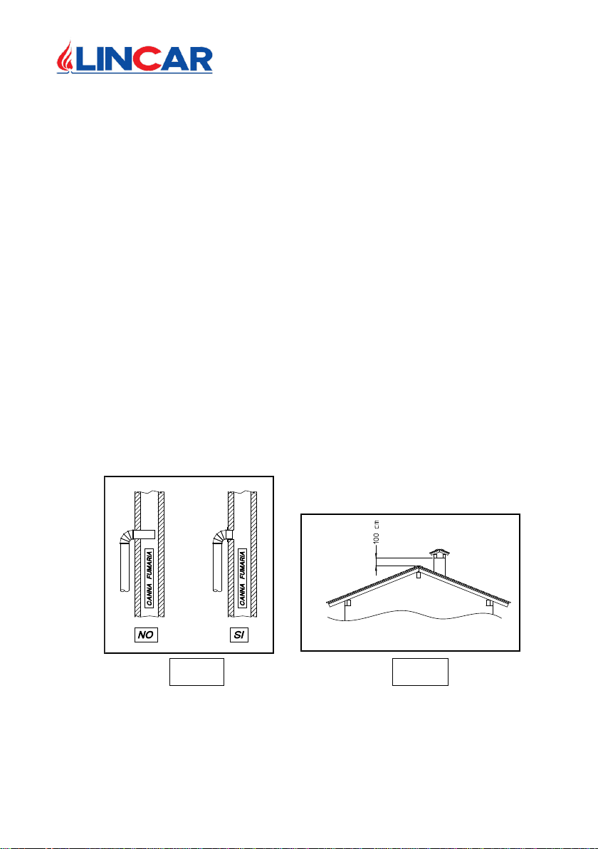
When joining the pipe to the flue, the former shall never overlap into the flue (Figure 3) and the connection
shall be properly sealed.
The correct operation of the cook stove is granted exclusively by a good draught of the flue. The minimum
value to be granted at 1 meter of distance from the exit on the collar of the plate shall be >10 Pa. These
instructions are requested in order to avoid the generation of carbon monoxide and the possible hazards
from carbon monoxide.
In case of bad weather conditions (phenomena of thermal inversion), pay particular attention to the emission
of fumes and gases and to the conditions of the draught.
In cases of incorrect feeding of the cook stove or lack of air for combustion, the room could fill with smoke or
unburned gases could come out. In that case, let the fire burn down and check for eventual occlusions in the
pipes and check the cleanness of the pipes. When the pipes are already partially occluded, the formation of
deposits on the pipes and into the flue increases rapidly and jeopardizes its optimal function.
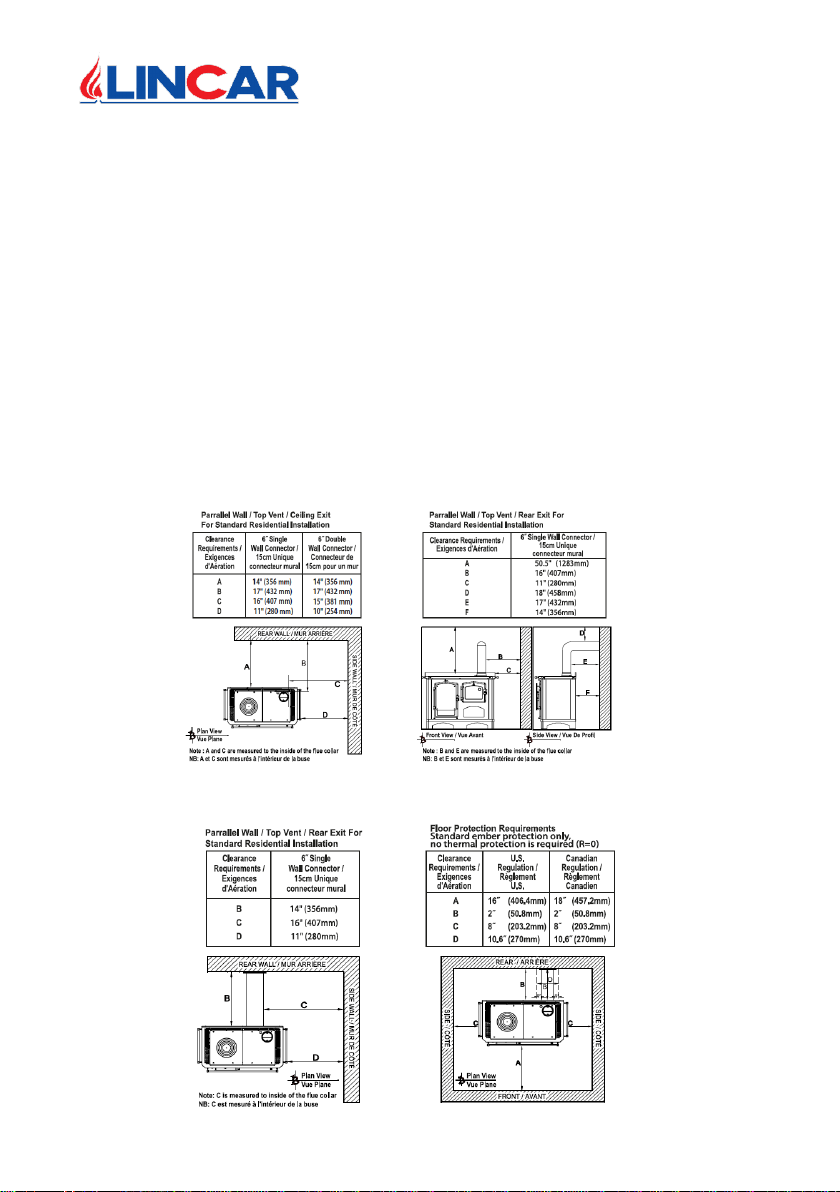
5.1 POSITIONING AND CONNECTION TO THE FLUE
For a correct operation, the cook stove shall be installed in the proximity of the flue. The connection
between cook stove and flue shall be as short as possible, in order to avoid annoying problems of
condensation in the pipes and, in any case, an anomalous operation of the cook stove itself.
When performing the connection, it is advisable:
Avoid an excess of bends (no more than two). (Figure 5).
Avoid long segments of horizontal pipe (max 30% of the whole vertical length). (Figure 5)
Incline the horizontal segments by 10-15% towards the flue to ease the evacuation of the fumes.
(Figure 5)
Try to have the vertical section of the pipe superior to 1.5 m. (Figure 5)
Absolutely avoid that the metal pipe overlaps into the flue. (Figure 3)
Properly seal the connection point between pipe and flue.
Use, in conformity with the current safety norms, pipes of adequate thickness and with a diameter
compatible with the collar supplied with the cook stove.
DO NOT CONNECT THIS UNIT TO A CHIMNEY FLUE SERVING ANOTHER APPLIANCE.
5.2 FLUE AND CHIMNEY POT
The flue is essential for a good operation of any solid fuel heating device. The depression, commonly
known as draught, is related to the height of the flue, which shall never be inferior to five meters, with
a section of at least 20x20 cm. It is important that the flue has no narrowing or air infiltrations that
could reduce the correct operation.
The minimum value of the depression to be granted at 1 meter of distance from the exit of the collar
on the plate shall be at least 10 Pa. With inferior values, the flame will be weak with formation of soot
and bad for the pipes, causing a possible exit of smoke from the door when loading wood, as well as
very low efficiency.
It is important that the flue serves only one cook stove. If several pipes should converge in the same
flue, the draught will be irregular, with consequences on the good operation of the cook stove.
If the latter condition is compulsory, the pipe shall be extended into the flue, until a sufficient draught
could be restored. (Figure 5)