Mi Swaco TOGA User manual

ManualPartNumber:90‐90‐885(Rev.B)
Installation,OperationandMaintenanceManual
For
TOGA*
TotalGasContainmentSystem

DISCLAIMER
RecommendationsmadebyM‐ISWACOareadvisoryonly.M‐ISWACOshallnotbe
liableunderanyguaranteesorwarranties,expressedorimplied,inanymannerorform,
ANDALLWARRANTIES,EXPRESSEDORIMPLIED,AREHEREBYSPECIFICALLY
EXCLUDED,andM‐ISWACOshallnotbeliableforthefailuretoobtainanyparticular
resultsfromtheuseofanyrecommendationmadebyitorfromtheuseofthismaterial.
InnoeventshallM‐ISWACObeliableforincidentalorconsequentialdamages.
©1975M‐ILLCAllrightsreserved.*MarkofM‐ILLC
Publicationdate:November2008
Allotherproducts,brand,ortradenamesusedinthispublicationarethetrademarksor
registeredtrademarksoftheirrespectiveowners.
Allrightsreserved.Thispublicationisthepropertyof,andcontainsinformationproprietaryto
M‐ISWACO.Nopartofthispublicationmaybereproducedinanyformorbyanymeans,
includingelectronic,mechanical,orotherwise,withoutthepriorwrittenpermissionof
M‐ISWACO.
Informationcontainedwithinthispublicationissubjecttochangewithoutnotice.

90‐90‐885 (Rev.B)
TOGA*1‐1
Section1INTRODUCTION
1‐1TABLEOFCONTENTS
1‐1.1ListofParagraphs
Sect
ParaTitlePage
1INTRODUCTION
1‐1TABLEOFCONTENTS......................................................................................1‐1
1‐2Contactinformation.............................................................................................1‐4
2MAINDATA
2‐1Functionaldescription.........................................................................................2‐1
3TECHNICALDESCRIPTION
3‐1PrinciplesorTheoryofoperation......................................................................3‐1
4PREPARATION
4‐1Preparationofequipmentforinstallation........................................................4‐1
4‐2Equipmentinstallation........................................................................................4‐2
4‐3DGASSER*Capacity‐vs‐CentrifugalPumpOutput....................................4‐8
5OPERATINGINSTRUCTIONS
5‐1MUD/GASSEPARATOR*operation................................................................5‐1
5‐2DGASSER*operation.........................................................................................5‐3
5‐3StoppingtheDGASSER*....................................................................................5‐4
6MAINTENANCE
6‐1safetysummary
6‐2Sparepartsneededfor2‐yearsoperation.........................................................6‐2
6‐3MAINTENANCEOFMUD/GASSEPARATOR*............................................6‐4
6‐4MAINTENANCEOFDGASSER*.....................................................................6‐6
6‐5Faultfindingandcorrectionofirregularities...................................................6‐7
7SPAREPARTSLIST
7‐1TOGA*(LandandOffshoreversion)
8ATTACHMENTS
8‐1TechnicalBulletin(TB152).................................................................................8‐1

90‐90‐885(Rev.B)
1‐2TOGA*
1‐1.2ListofTables
Sect
TableTitlePage
4PREPARATION
4‐1MotorWiring.......................................................................................................4‐7
4‐2DGASSER*CapacityAndHorsepowerRequired.........................................4‐8
6MAINTENANCE
6‐1RecommendedSparePartsList.........................................................................6‐2
6‐2TroubleshootingTheMUD/GASSEPARATOR*............................................6‐7
6‐3TroubleshootingTheDGASSER*.....................................................................6‐8
7SPAREPARTSLIST
7‐1TOGA*System,LandVersion9620248............................................................7‐3
7‐2TOGA*System,OffshoreVersion9620249......................................................7‐5
7‐3MUD/GASSEPARATOR*,LandVersion9620244.........................................7‐9
7‐4MUD/GASSEPARATOR*,OffshoreVersion9620245...................................7‐13
7‐5MUD/GASSEPARATOR*FloatControlValve9620226...............................7‐17
7‐6BackFlowManifold9620199.............................................................................7‐21
7‐7BackPressureManifold9620384.......................................................................7‐23
7‐8DualVacuumPumpD‐GASSER*9620311‐01and9620311‐02.....................7‐27
7‐9D‐GASSER*TankandSkid9620002.................................................................7‐31
7‐10D‐GASSER*FloatControlValve9620040........................................................7‐33
7‐11D‐GASSER*Float9620045.................................................................................7‐35
7‐12D‐GASSER*DischargePipe9620063................................................................7‐37
7‐13D‐GASSER*SuctionPipe9620312....................................................................7‐39
7‐14D‐GASSER*VacuumPumpandMotor9620167‐01and
9620167‐02(230/460V,60Hzand380V,50Hzversion)...............................7‐41

90‐90‐885 (Rev.B)
TOGA*1‐3
1‐1.3ListofFigures
Sect
FigureTitlePage
4PREPARATION
4‐1ErectingTheMUD/GASSEPARATOR*...........................................................4‐2
4‐2SuggestedLocationsOfDGASSER*.................................................................4‐5
4‐3JetPressuretoFlowRateCurves.......................................................................4‐9
5OPERATINGINSTRUCTIONS
5‐1MUD/GASSEPARATOR*FloatValve.............................................................5‐2
5‐2BackPressureManifold......................................................................................5‐3
7SPAREPARTSLIST
7‐1TOGA*System,LandVersion9620248.............................................................7‐2
7‐2TOGA*System,OffshoreVersion9620249......................................................7‐4
7‐3MUD/GASSEPARATOR*,LandVersion9620244..........................................7‐7
7‐4MUD/GASSEPARATOR*,OffshoreVersion9620245...................................7‐11
7‐5MUD/GASSEPARATOR*FloatControlValve9620226................................7‐16
7‐6BackFlowManifold9620199..............................................................................7‐20
7‐7BackPressureManifold9620384.......................................................................7‐22
7‐8DualVacuumPumpD‐GASSER*9620311‐01and9620311‐02......................7‐25
7‐9D‐GASSER*TankandSkid9620002.................................................................7‐30
7‐10D‐GASSER*FloatControlValve9620040.........................................................7‐32
7‐11D‐GASSER*Float9620045..................................................................................7‐34
7‐12D‐GASSER*DischargePipe9620063................................................................7‐36
7‐13D‐GASSER*SuctionPipe9620312.....................................................................7‐38
7‐14D‐GASSER*VacuumPumpandMotor9620167‐01and
9620167‐02(230/460V,60Hzand380V,50Hzversion)...............................7‐40
7‐15D‐GASSER*VacuumPumpCompressor8913003..........................................7‐44

90‐90‐885(Rev.B)
1‐4TOGA*
1‐2CONTACTINFORMATION
M‐ISWACO
P.O.Box42842
Houston,TX77242‐2842
www.miswaco.com
GlobalSales/TechnicalSupport
Tel:281‐988‐1866
Fax:281‐988‐1889
WATS:1‐800‐654‐0660

90‐90‐885 (Rev.B)
TOGA*2‐1
Section2MAINDATA
2‐1FUNCTIONALDESCRIPTION
TheM‐ISWACOTotalGasContainment(TOGA)Systemisdesignedtocontain,separateandremovethefree
andentrainedgasesfromthedrillingfluidcirculatedfromthewellbore.Totalcontainmentandremovalofthe
gasesfromthefluidisaccomplishedthroughauniquecombinationofM‐ISWACO’sMUD/GASSEPARATOR*
andHighVacuumD‐GASSER*.Thegasisremovedfromthedrillingfluidandventedintoaclosedflaresystem
andburnedatasafedistance,topreventanytoxicorcombustiblegasfromescapingaroundtherigfloorormud
pitarea.

90‐90‐885(Rev.B)
2‐2TOGA*
THISPAGEINTENTIONALLYLEFTBLANK

90‐90‐885 (Rev.B)
TOGA*3‐1
Section3TECHNICALDESCRIPTION
3‐1PRINCIPLESORTHEORYOFOPERATION
Thedrillingfluidcirculatedfromawellmayincludegasand/orformationliquidswhichhaveenteredthewell
bore.Asthefluidapproachesthesurfacethehydrostaticpressureisreduced,andthegasbubblesinthefluid
expandandformheadsormassivepocketsofgas.Theseheadsofgasorgascutmudarecirculatedfromthewell
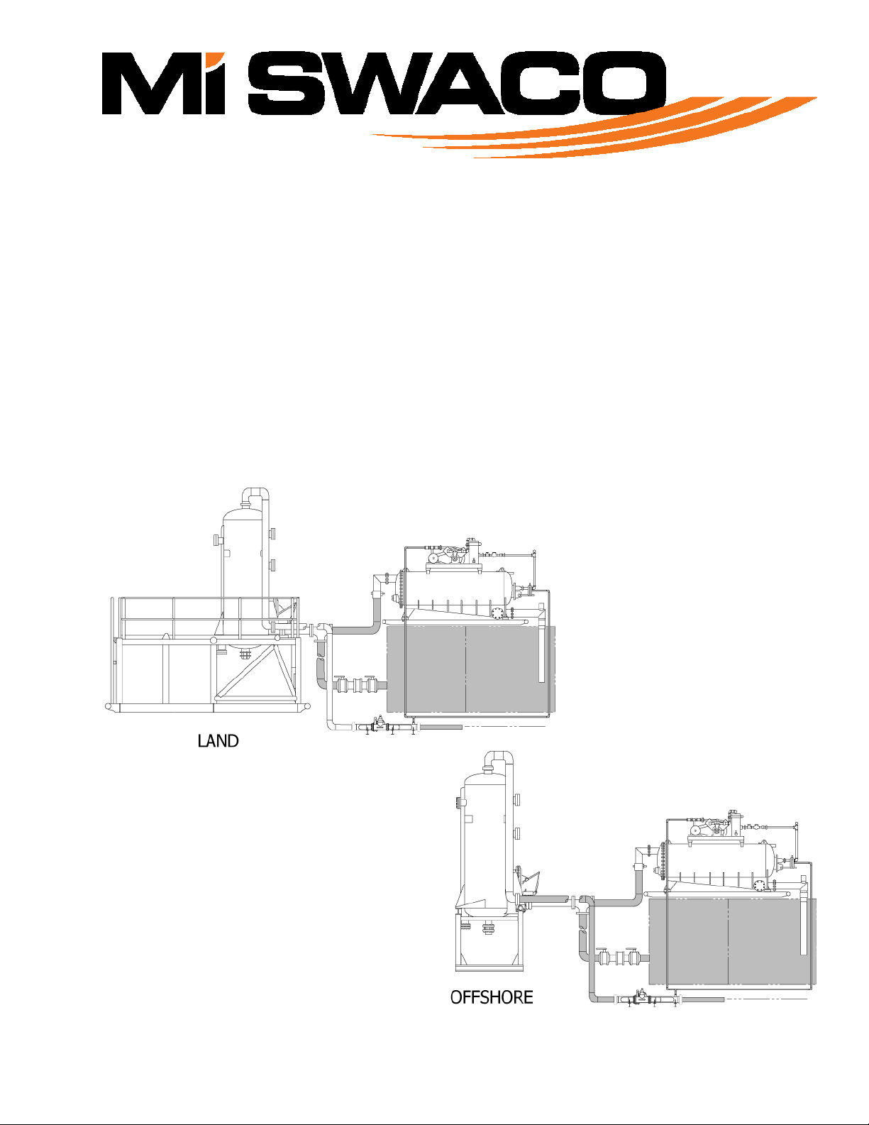
borethroughtheflowlineorchokemanifoldintoasixinchinletlineontheMUD/GASSEPARATOR*.Thefree
gasisseparatedfromthefluidbyaseriesofbafflesinthevesselandventedintotheflarelinethroughaneight
inchlineonthetopoftheMUD/GASSEPARATOR*Vessel.
3‐1.1MUD/GASSEPARATOR*FloatValve
TheFloatoperatedcontrolvalveinsidetheMUD/GASSEPARATOR*vesselopenstopreventoverfillingofthe
VesselandclosestomaintainaliquidsealontheeightinchMudReturnLine.Theliquidsealpreventsthe
separatedgasfrombeingdischargedintothemudreturnline.
3‐1.2BackPressureManifold
TheBackPressureManifoldisinstalledintheMUD/GASSEPARATOR*VentLinetodampenthesurgeeffects
fromtheexpandinggasandpreventtheblowingofmudintotheVentLine.Abackpressuresettingof15‐50psi
(1.1–3.5kg/cmsquared)isrecommendedontheMUD/GASSEPARATOR*Vessel.
3‐1.3D‐GASSER*
ThegascutmuddischargedfromtheMUD/GASSEPARATOR*isdrawnintotheD‐GASSER*Vesselbya
vacuumforcecreatedbythedischargepipelowpressurejetassembly.Thefluidisdistributedoverabaffleina
thinevenlydispersedlayer.Thisthinlayeroffluidisexposedtoavacuumofatleasteightinchesofmercury
createdbythevacuumpump.Thevacuumforceremovestheentrainedgasesfromthefluidandthedegassed
fluidisdischargedintotheactivesystem.TheentrainedgasremovedfromthefluidbytheD‐GASSER*isvented
intotheclosedflaresystem,down‐streamoftheMUD/GASSEPARATOR*BackPressureManifold.
TheTOGA*systemutilizesM‐ISWACO’sstandardMUD/GASSEPARATOR*andD‐GASSER*whichhavebeen
specificallymodifiedtoassuretotalcontainmentandcontrolofthetoxicgascutmud.ThemodifiedD‐GASSER*
includestwocompletevacuumpumpsystems.Thevacuumpumpexhaustlinesareconnectedthrougha
manifoldcontainingaseriesofcheckvalvestopreventthepossibilityofblowbackfromtheflarelines.Plug
valveslocatedoneithersideofthecheckvalvesareusedtoprovideameanstoisolateandsafelyrepairorreplace
eithervacuumpumpsystemwhiletheotherisstilloperationalaswellastoconfigurethevacuumpumpsystems
foralternativemethodsofoperation.Thefirstalternativeistorunbothvacuumpumpsystemssimultaneouslyto
assuremaximumdegassingefficiencywhenlargevolumesofgasareencountered.Thesecondalternativeisto
provideameansforredundancyintheeventtheprimaryvacuumpumpsystemfailsduringkickconditions.

90‐90‐885(Rev.B)
3‐2TOGA*
3‐1.3D‐GASSER*Continued
AnothermodificationtotheD‐GASSER*isthe3‐wayfloatcontrolledvalvetopreservetheTOGA*System
integrityoftotallycontainingthegasfromthewell.The3‐wayfloatcontrolledvalveisconnectedtotheexhaust
sideofthevacuumpumpstopreventatmosphericairfromenteringthevesselwhenthevalveopenstobreakthe
vacuumwhilecontrollingthefluidlevelinthevessel.Thegasenteringthevesselthroughthe3‐wayvalveis
simplyrecycledgascomingfromthevacuumpumps.
3‐1.4BackFlowManifold
AteelocatedontheMUD/GASSEPARATOR*mudreturnlineconnectsthesuctionlineoftheD‐GASSER*and
themudlinefromtheactivesystemwiththedischargeoftheMUD/GASSEPARATOR*.Themudlinetothe
activesystemmaintainsaconstantflowoffluidtotheD‐GASSER*whenlowflowconditionsfromthe
MUD/GASSEPARATOR*exist.Themudlinefromtheactivesystemhasacheckvalveassemblytoassurethat
gascutmuddischargedbytheMUD/GASSEPARATOR*willnotbypasstheD‐GASSER*andentertheactive
system.

90‐90‐885 (Rev.B)
TOGA*4‐1
Section4PREPARATION
4‐1PREPARATIONOFEQUIPMENTFORINSTALLATION
Itisadvisabletomakeapreinstallationinspectionoftherigsitetoassureproperinstallation.Therelative
positionsoftheD‐GASSER*andMUD/GASSEPARATOR*areextremelyimportanttoassurecorrectoperation
andefficiencyoftheTOGA*system.TheMUD/GASSEPARATOR*mudreturnlineshouldbeaminimumoffour
feet(1.2m)belowtheD‐GASSER*suction.TheMUD/GASSEPARATOR*mudreturnlineshouldalsobeeven
withthehighestfluidlevelexpectedinthemudtank.ThisorientationoftheMUD/GASSEPARATOR*will
maintainaconstantflowoffluidtotheD‐GASSER*whenlowflowratesfromtheMUD/GASSEPARATOR*are
encountered.
4‐1.1ErectingTheLandVersionMUD/GASSEPARATOR*(Figure4‐1)
Beforebeingplacedinposition,theMUD/GASSEPARATOR*shouldbeerectedinanareawhichallowsfora
winchtruckorcranetoworkattheendandsideoftheskid.Firstinstallallrailingsectionssecurelyinplaceon
thetopoftheskid.
ToerecttheMUD/GASSEPARATOR*,positionthewinchtruck/craneattheendoftheskidwherethebottomof
thevesselispositioned.TheA‐frameonthewinchtruckshouldbehighenoughtoraisetheliftingeye(1)
attachedtothetopofthevessel11feet(3.4m)abovetheskid.Opentheexpandedmetalflooring(2)andconnect
thewinchlinetotheliftingeye(1)onthevessel.Raisethevesselpasttheverticalposition,andplacethesupport
beam(3)underthefreeedgeofthevesselandlowerthevesselontothebeam.Closetheflooringgratesandplace
thesupportbeamsunderthemasrequired.
TheMUD/GASSEPARATOR*isnowreadyforplacement.Liftingeyes(4)areprovidedateachendoftheskid.
WhentheMUD/GASSEPARATOR*isplacedinthedesiredposition,checktobesurethebottomoftheskidis
levelandtheMUD/GASSEPARATOR*vesselisinaverticalposition.
ToobtaindifferentheightadjustmentsoftheMUD/GASSEPARATOR*removethepins(5)lockingtheupperand
lowerlegsectionsoftheskid.Raisetheentireuppersectionoftheskidbytheliftingeyes(4)totherequired
height,andre‐insertthelockingpinsineachleg.
4‐1.2SecuringTheOffshoreMUD/GASSEPARATOR*
BeforeraisingtheMUD/GASSEPARATOR*,checkthatthefourboltssecuringthevesseltothestandareinplace
andtightened.
Anyliftingdevicebeingusedshouldbehighenoughtoraisetheliftingeyeattachedtothetopofthevessel18
feet(5.5m)abovetherigfloor.Connecttheliftingdevicetotheliftingeyeonthevessel.Raisethevesseltothe
verticalposition,andalignthestand‐to‐rigmountingholes.Securethestandtotherigfloorthenremovemetal
shippingbracefromthevessel.

90‐90‐885(Rev.B)
4‐2TOGA*
4‐1.1ErectingTheLandVersionMUD/GASSEPARATOR*Continued
Figure4‐1.ErectingTheMUD/GASSEPARATOR*
4‐1.3D‐GASSER*Inspection
TheD‐GASSER*andaccessoryequipmentshouldbeinspectedforshippingdamage.Manipulateallcontrolsand
movingpartstodeterminewhethertheyaremechanicallyoperable.Iftheinspectionrevealsnodamagetheunit
isreadyforinstallation.
4‐2EQUIPMENTINSTALLATION(SEEFIGURE7‐1ORFIGURE7‐2)
4‐2.1ChokeManifoldLinesAndBlowoutPreventerBypassLines
ThecustomerwillprovidethesixinchlinesfromthechokemanifoldandBOPbypasstothe
MUD/GASSEPARATOR*.Theselinesshouldbeasstraightastheriglayoutpermits.Ifturnsarenecessary,they
shouldbemadeusingatee.Theteeendoppositetheinletshouldbecappedusingaplugfilledwithanabrasion
resistantmaterialsuchaspewter.
4‐2.2MudReturnLine
BeforeconnectingthemudreturnlinetotheD‐GASSER*suctionline,checktoseethattheeightinchbutterfly
valve(fluidseallevelcontroller)(Figure7‐3,Item26orFigure7‐4,Item22)ispositionedsoitwillclosewhenthe
operatingleverisraised.Ifthevalvedoesnotcloseitmayhavebeeninstalledbackwardsorrotatedtoplacethe
operatingleverontheoppositeside.Becertainthebutterflyvalveisoperatingcorrectlybeforecontinuingwith
theinstallationprocedureofthemudreturnline.

90‐90‐885 (Rev.B)
TOGA*4‐3
Ifnecessary,adjustthearmlengthsandsettingsonthevalvestemandstuffingboxshaft.Thevalveisproperly
adjustedwhenslightlylessthanthetotalavailableupwardmovementofthefloatwilloperatethevalvefromthe
closedtothefullyopenposition.Intheclosedpositiontheangleoftheconnectingarmonthevalvelevershould
beatleast40degrees.
TheeightinchpipeandaccessoriesrequiredtoconnecttheteeontheMUD/GASSEPARATOR*mudreturnline
withtheD‐GASSER*suctionpipeandthemudtanksaretobefurnishedbythecustomerandfabricatedon
location.Thelinefromthemudtankwillhaveapre‐assembledcheckvalveassemblytopreventanyflowfrom
theMUD/GASSEPARATOR*totheactivesystem.ThislineisconnectedtotheMUD/GASSEPARATOR*
dischargeandtheD‐GASSER*suction.
4‐2.3GasVentLine
ATTENTION!
THEGASVENTLINEMUSTBEINSTALLEDWITHACONTINUOUS
GRAVITYDRAINAGETOWARDTHEFINALEXITPOINT.DONOTALLOW
THISLINETOHAVEALOWPOINTWHICHCANFILLWITHLIQUID.ANY
SUCHACCUMULATIONDELAYSTHEVENTINGOFGASUNTILENOUGH
PRESSUREBUILDSUPTOPUSHTHELIQUIDTHROUGHTHELINE..THIS
PRESSUREINCREASEMAYCAUSETHELINETOPOUNDSEVERELY
RESULTINGINDAMAGETOEQUIPMENTANDPOSSIBLEINJURYTO
PERSONNEL.
ThefirstsectionofgasventlineextendsfromthetopoftheMUD/GASSEPARATOR*vesseltoapointnearthe
eightinchmuddischargevalve.Aneightinchswingpipeisprovidedtocompensateforthevesselheightwhen
raisingtheadjustableskid.Thisswingpipeisconnectedtotheinletofthebackpressuremanifoldusinga
Victauliccoupling.
Thegasventlineshouldbeassembledwhereitwillnotallowfluidtoaccumulateintheline.Theexhaustfrom
thedualvacuumpumpsontheD‐GASSER*shouldbeconnectedtotheflarelinedown‐streamoftheback
pressureregulatorassembly.

90‐90‐885(Rev.B)
4‐4TOGA*
4‐2.4D‐GASSER*
TheD‐GASSER*shouldbeinstalledonornearthemudpitwiththebottomoftheskidnottoexceed3feetabove
thenormaloperatingmudlevel.Suctionanddischargepipesshouldbekeptasshortaspossible.Forbestresults,
thebottomofthesuctionlineshouldbeatleast4inches(10.2cm)abovethebottomofthetank,atleast3feet
(0.9m)belowtheoperatingmudlevel,and12inches(30.5cm)ormoreawayfromthesideofthetank.The
dischargeassemblyshouldbeatleast3feet(0.9m)longandshouldextendbelowthemudpitʹsminimum
operatingmudlevel.InordertoreturntheexcessvolumeofmudthatisnormallyhandledbytheD‐GASSER*to
thefirstpit,anequalizerlineshouldbeprovidedtopermitthemudtoflowbetweenthetwopitswhilethe
equipmentisoperatingatahighlevel.
Oninitialinstallations,itmaybenecessarytoadjusttheturnbucklethatisattachedtothe3‐wayvalvesothatthe
stemofthevalveextends3/8inch(0.95cm)outthebottomofthevalvebody,whentheballiscompletelydown,
restingonthebottomofthetroughinsidethevacuumvessel.
4‐2.5D‐GASSER*VacuumAndFluidControl
NOTE:
THEFLOATLEVELSHOULDBEVISUALLYSETBEFORETHEDISCHARGE
PIPINGISCONNECTEDTOTHED‐GASSER*.
Thecustomerwillfurnishpipingnecessarytoconnectthevacuumpumpoutletmanifoldtotheflareline
downstreamofthebackpressurevalveassembly.Amodified3‐wayvalveisusedontheD‐GASSER*.The
bottomofthe3‐wayvalveisconnecteddownstreamofthebackpressureregulatorassemblyandusesventedgas
tobreakthevacuum,therebycontrollingthefluidlevelinthevesselwhilemaintainingventgascontainment.The
turnbuckleconnectedtothefloatadjuststhefluidlevelinthevesselbysettingthevalvetobreakthevacuumata
specificfloatlevel.
4‐2.5.1MudJet
TheD‐GASSER*usesalowpressurejetfedbyanexternal,customerfurnishedcentrifugalpumpandusea1‐1/2
inchnozzle.JetvolumeandpressurerequirementsforvariousD‐GASSER*throughputvolumesandmud
weightsmaybedeterminedfromtheperformancedatafoundinTable4‐2andFigure4‐3.

90‐90‐885 (Rev.B)
TOGA*4‐5
Figure4‐2.SuggestedLocationsOfD‐GASSER*

90‐90‐885(Rev.B)
4‐6TOGA*
4‐2.5.1VacuumPumpAssemblies
WARNING!
THISEQUIPMENTEMPLOYSVOLTAGESWHICHAREDANGEROUSTO
LIFEANDMAYBEFATALIFCONTACTEDBYPERSONNEL.
EXERCISEEXTREMECAUTIONWHENWORKINGWITHELECTRICAL
CIRCUITRY,ESPECIALLYWHENSTARTERENCLOSURESANDMOTORS
HAVETHEIRCOVERSREMOVEDFORCURRENTANDVOLTAGETESTS.
BEFOREMAKINGANYELECTRICALCONNECTIONS,MAKESURETHE
POWERSOURCEISDISCONNECTEDANDTHESTARTERISINTHEOFF
POSITION.
A3horsepowermotorisusedtodriveeachvacuumpump.Anexplosionproofmanualstarterissuppliedwith
eachvacuumpumpassemblyandispre‐wiredatthefactory.Afterithasbeenverifiedthatthemotorandstarter
arewiredforthepropervoltage,theelectricalpowersourcecanbeconnectedtothestarters.Table4‐1is
providedasanaidwhenconnectingthemotorstothepowersource.
Afterconnectingthepowersource,momentarilystarteachmotortomakecertainthevacuumpumprotatesin
thesamedirectionasindicatedbythearrowlocatedononeofthevacuumpumpsheavespokes.Therotationof
any3phasemotorcanbereversedbychanginganytwowiresinthestarterbox.

90‐90‐885 (Rev.B)
TOGA*4‐7
Table4‐1.MotorWiring
WARNING!
ALWAYSdisconnectpowerbeforeattemptingANYmaintenanceor
repairwork.
380V‐AC
50Hz
3Phase
1‐toline1*
2‐toline2*
3‐toline3*
4‐7
8‐5
9‐6
*Tochangerotation,changeanytwowiresonline.
TYPICALWIRINGDIAGRAM
(50&60Hz)
LOWVOLTAGE
MOTORWIRINGDIAGRAM
HIGHVOLTAGE
MOTORWIRINGDIAGRAM

90‐90‐885(Rev.B)
4‐8TOGA*
4‐3D‐GASSER*CAPACITY‐VS‐CENTRIFUGALPUMPOUTPUT
MaximumD‐GASSER*flowratesthatcanbeobtainedwiththe1‐1/2inchjetandmudpumpimpellersizesfor
boththe5”x6”and6”x8”Missionpumpsareshowninthetablebelow.Inaddition,thehorsepowerrequiredto
movethemudisalsoshown.Thehorsepowerrequirementsshowninthetablearebasedonamudweightof10
lb/gal(1.2kg/liter).Whiletheflowrateswillremainthesameforothermudweights,therequiredhorsepower
willbedifferent.Tocorrectthehorsepowerlistedforadifferentmudweight,dividethemudweightby10lb/gal
(1.2kg/liter)togetacorrectionmultiplier.Multiplythehorsepowervalueshowninthetablebythecorrection
multipliertoobtainthehorsepowerrequirementforthatmudweight.
EXAMPLE:A10”impellerina5”x6”pumppoweredbyadieselengineat1600RPMwillprovidejetpowerfor
handling625GPMthroughtheD‐GASSER*.Horsepowerrequiredfor15lb/galmudis:15/10x16=24HP.
Table4‐2.D‐GASSER*CapacityAndHorsepowerRequired
IMPELLERSIZE
1600RPM1750RPM
FlowRateHorse‐
power*
FlowRateHorse‐
power*
5ʺx6ʺPumpgpmlpmgpmlpm
9ʺ 490185011590223021
10ʺ 625237016700265027
11ʺ 720272024800308838
12ʺ 800303039875331049
6ʺx8ʺPump
9ʺ 450170022515195025
10ʺ 600227029660250033
11ʺ 700265038760288044
12ʺ 770291044875331057
13ʺ 875331059950360070
*Horsepowershowniscalculatedfor10lb/gal(1.2kg/liter)mud.
D‐GASSER*volumewillbereducedslightlyandthehorsepowerincreasedproportionallyifabnormalfriction
(suchaslongmudlineloss)isincurredbetweenthepumpandthejet.

90‐90‐885 (Rev.B)
TOGA*4‐9
4‐3D‐GASSER*CAPACITY‐VS‐CENTRIFUGALPUMPOUTPUTCONTINUED
D‐GASSER*performancecurvesareillustratedinthefigurebelow.Ifconditionsarisewhereadditionalvolumes
arerequired,contactedtheM‐ISWACOtechnicalservicesengineeringdepartment.
Figure4‐3.JetPressuretoFlowRateCurves

90‐90‐885(Rev.B)
4‐10TOGA*
THISPAGEINTENTIONALLYLEFTBLANK
Table of contents
Popular Industrial Equipment manuals by other brands

Talet Equipment
Talet Equipment 3000 Series PARTS & OPERATORS MANUAL

AESSEAL
AESSEAL SWFF-TF Installation, operation & maintenance instructions

CMD
CMD 90 Series quick start guide

SMC Networks
SMC Networks IBG Series Operation manual

Victaulic
Victaulic UM Series Installation, Maintenance, & Testing Manual

Pfeiffer Vacuum
Pfeiffer Vacuum TC 1200 PN operating instructions