manuals.online logo
Brands
  1. Home
  2. •
  3. Brands
  4. •
  5. CMD
  6. •
  7. Industrial Equipment
  8. •
  9. CMD 90 Series User manual

CMD 90 Series User manual

200mm
332mm
Check there is sufcient
clearance under the
oor to accept the box
and cables.
Measure, mark and cut
the aperture in the oor.
200 x 332mm -0/+3mm
tolerance.
Clear away debris from
the aperture to allow
proper installation of the
oor box.
Prepare the oor area (for screw xed oor box)
90 series (oor box) Installation, user and care guide
Part No: 134250 Issue No: 001
Screw xed oor box
Screed xed oor box
(with ingress blocking tape)
Add in and wire up the
desired accessory plates
if not already installed.
Use a suitable cover to
protect the insides from
screed during pouring
process.
Add in and wire up the
desired accessory plates
into the box.
Lower the lid trim into
place as shown. Check
the box is clean and free
of debris rst.
Ensure box is secured in
place to prevent oating
during the pouring
process. Pour the screed.
Lower and x the trim
into place as shown.
Check the box is clean
and free of debris rst.
Secure with 2x screws
that were removed in
the rst step. Reverse
steps to remove.
Remove the cover from
the box when the screed
is fully set.
Lower the lid into the
trim. Lay nished oor
covering to match
height of lid.
Lift up the ring pull
in the centre of the
handles.
Remove the lid and trim
from the box base if not
already separated.
Place the box in desired
location. A ribbon screed
may be required to meet
the nished oor level.
Carefully pull up the lid
with the handles and
place to one side.
Angle the box and lower
into the aperture in the
oor if the box is pre-
wired.
Use a screw driver on
each corner jacking leg
to adjust the height of
the box up to 10mm.
Reverse the process to
close the lid.
Screw the box base to
the oor substrate with
4x suitable screws at the
points shown.
Remove the required
knockouts and feed
the desired cables and
conduit to the box.
Screw xed installation (into raised access oor)
Screed xed installation (onto concrete/hard oor)
Lid operation
Raised access oor
Ribbon screed layer Jacking legs
Measure the inside
dimensions of the lid
and carefully cut out the
inll material.
Measure the supplied
handles and cut out a
suitable recess. Screw
handles in place.
Secure inll into the lid
and install into the oor
box when ready.
Fitting the lid inlay and handles
CMD Ltd, Rotherham, S65 1EN, UK
T: 01709 829 511 E: [email protected]
‘CLICK’
Additional information
• Installation is to be carried out in accordance with relevant Health & Safety regulations and only to be carried out by a skilled or competent person.
• It is recommended that oor boxes are not installed in high trafc areas.
• The product should be installed to comply with the relevant national standards and be inspected and tested prior to being put into service (in the UK BS
7671 Wiring Regulations).
• Isolate the supply before installation or repositioning. Any locking mechanisms must be used and fully engaged.
• Incorrect use could lead to risk of electrocution.
• Product to be used only for the intended purpose of distributing power in a commercial environment.
• Do not misuse, dismantle or re-congure the product because doing so will invalidate the warranty.
• If a product incorporates RCD protection, the RCD should be regularly tested in-line with current standards.
Safety
• Refer to the Declaration of Conformity.
Standards
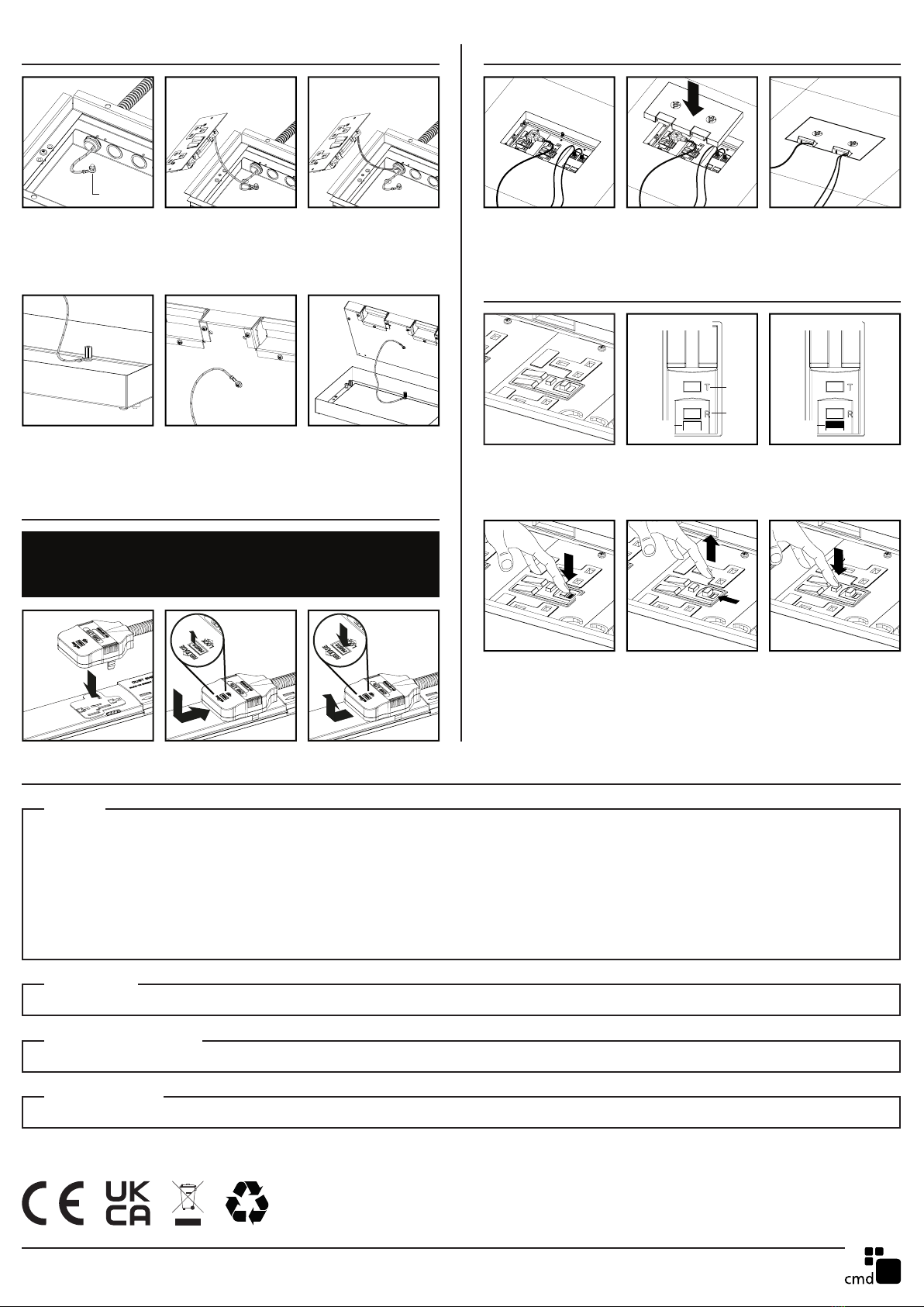
Tap-off engagement/release
**WARNING**
An unterminated tap-off MUST NEVER be connected to a live track.
Provided that it is off load, a terminated tap-off may be removed/
inserted into a live track. Conduit must be bonded to Earth.
To reset after it has
tripped, press and hold
the grey reset button
until a click is heard.
The indicator will change
to show it is now active.
Remove your nger from
the reset button.
A qualied person
should test the SRCD
function periodically to
comply with standards.
A qualied or fully
competent person
should test the SRCD
before rst use.
Plug any power and
data cables into their
respective sockets.
Connect an earth link to
the underside of the lid
trim with a suitable ring
terminal.
When active, the SRCD
indicator window is
lled with a red marker.
If possible, try to keep
power and data cables
segregated when using
the cable guides.
Connect the earth link
from the trim to the
underside of the lid in
the centre.
When the SRCD trips,
the red marker in the
indicator window
recedes as shown.
Carefully close the lid
and ensure the cables
are fed out through the
cable access brackets.
The lid and the trim are
now connected with the
earth link.
Testing and resetting SRCD socket (if applicable)
Cable management
‘CLICK’
Test
Reset
Indicator
up
Indicator
down
Active SRCD state Tripped SRCD state
Lid trim Lid
Earthing the box and sockets
Earth stud
Standard Earth Clean Earth (C/E) Low Noise
The box base must be earthed with a suitable ring terminal to the integrated
earth stud. To ensure the sockets are earthed, a link will be required from
the box earth stud to the socket earth. On Clean Earth (C/E) Low Noise
installations these should be wired directly to the Clean Earth CPC (Circuit
Protective Conductor).
• Clean using a dry cloth. No abrasives or solvents to be used on the product. Do not drop or expose to moisture.
Product care
Further guidance
• If viewing this sheet prior to specication/technical documentation purposes, be aware of potential plug clashes with certain socket plate orientations.

Other CMD Industrial Equipment manuals

CMD 23 Series User manual

CMD

CMD 23 Series User manual

CMD flexacier 9000 User manual

CMD

CMD flexacier 9000 User manual

CMD winflex DG User manual

CMD

CMD winflex DG User manual

CMD 20 Series Troubleshooting guide

CMD

CMD 20 Series Troubleshooting guide

CMD flexacier User manual

CMD

CMD flexacier User manual

CMD 22 Series User manual

CMD

CMD 22 Series User manual

Popular Industrial Equipment manuals by other brands

ABB +Q957 user manual

ABB

ABB +Q957 user manual

G.B.C BASIC EDGE 50 instruction manual

G.B.C

G.B.C BASIC EDGE 50 instruction manual

Tronair Batpak 11-6602-1000 Operation & service manual

Tronair

Tronair Batpak 11-6602-1000 Operation & service manual

Pilz PNOZ mi2p Operation manual

Pilz

Pilz PNOZ mi2p Operation manual

Clemco Zero BNP 6012 manual

Clemco

Clemco Zero BNP 6012 manual

Erskine Attachments V-Plow Operator's manual

Erskine Attachments

Erskine Attachments V-Plow Operator's manual

ABB HT610965 Operation manual

ABB

ABB HT610965 Operation manual

Morra MH 540 user manual

Morra

Morra MH 540 user manual

Eaton S090ST manual

Eaton

Eaton S090ST manual

GRIGGIO G 240 P4 instructions

GRIGGIO

GRIGGIO G 240 P4 instructions

Nexen AIR CHAMP HT45 user manual

Nexen

Nexen AIR CHAMP HT45 user manual

WTE V5 installation manual

WTE

WTE V5 installation manual

ABB HT845232 Operation manual

ABB

ABB HT845232 Operation manual

SMC Networks CJP Series Operation manual

SMC Networks

SMC Networks CJP Series Operation manual

JohnDow Industries JDI-AFT58 Operator's manual

JohnDow Industries

JohnDow Industries JDI-AFT58 Operator's manual

IMB MB9016A instruction manual

IMB

IMB MB9016A instruction manual

Clarke CUMB1 Assembly & operating instructions

Clarke

Clarke CUMB1 Assembly & operating instructions

amiad Arkal Spin Klin 2 user guide

amiad

amiad Arkal Spin Klin 2 user guide

manuals.online logo
manuals.online logoBrands
  • About & Mission
  • Contact us
  • Privacy Policy
  • Terms and Conditions

Copyright 2025 Manuals.Online. All Rights Reserved.