CSE Kingfisher PLUS+ Quick user guide

Kingfisher PLUS+
Superseded Hardware Reference Manual
7.12

Superseded Hardware Manual 7.12
www.cse-semaphore.com/mykingfisher
Page 2
Document Information
Document Control
Copyright Copyright CSE-Semaphore (Australia) Pty Ltd. ABN 35 006 805 910
www.cse-semaphore.com/mykingfisher, info.kingfisher@cse-semaphore.com
Intellectual Property CSE-Semaphore asserts ownership of the intellectual property contained herein and
claims copyright and authorship. CSE-Semaphore has and retains all rights of
ownership and use of the material herein in its on-going business.
Licence
This document is provided to the intended recipient(s) under a non-exclusive licence.
This licence permits Fair Use of the document for operational requirements, without
payment of further royalty or licence fee. Fair Use includes making copies of the
document for operational, backup and archive purposes. Fair Use includes distributing
copies of the document to other entities for the purposes of their performing related
works for the intended recipient(s). Fair Use does not include creating, selling or
distributing copies of the document for other purposes. All copies must retain this
statement of Intellectual Property and Copyright.
Revision History
Rev.
Date
Remarks
6.11
2/8/2011
Changed order of some chapters. Added PSU-4 power supply (higher power version of the PSU-3).
PS-xx temperature sensor wires are now red with a black stripe.
Added PS-22, IO-5 and MC-31 modules.
7.1
28/10/2011
Manual superseded by new layout and retained as the superseded hardware manual
7.12
22/2/2012
Rerelease coinciding with Hardware manual 7.12

Superseded Hardware Manual 7.12
www.cse-semaphore.com/mykingfisher
Page 3
Contents
1.1 PS-1/PSU-1: AC Supply Input ........................................................................................... 6
PS-1 Battery Charging States......................................................................................................... 7
PS-1/PSU-1 Specifications............................................................................................................. 8
Output Characteristics.................................................................................................................... 9
PS-1/PSU-1 Block Diagram ............................................................................................................ 9
PS-1/PSU-1 Module LEDs.............................................................................................................10
PS-1 - Additional Features.............................................................................................................10
PSU-1 Wiring Diagram ..................................................................................................................11
PS-1 Wiring Diagram – AC Supply.................................................................................................11
PS-1 Wiring Diagram – DC Supply ................................................................................................12
1.2 PS-10: AC Supply Input 90 to 260 VAC & PS-20: DC Supply Input 20 to 60 VDC.............13
PS-10-CU, PS-20-CU................................................................................................13
PS-10/PS-20 – Standard Specifications.........................................................................................14
PS-10-2/PS-20-2 – 24 V Specifications..........................................................................................15
PS-10/PS-20 – Block Diagram.......................................................................................................15
PS-10/PS-20 – Module LEDs.........................................................................................................16
PS-10/PS-20 - Additional Features................................................................................................16
PS-10 Wiring Diagram – AC Supply...............................................................................................17
PS-10 Wiring Diagram – DC Supply...............................................................................................17
PS-20 Wiring Diagram...................................................................................................................18
1.3 PSU-2: DC Supply Input, 18 to 36 VDC............................................................................19
PSU-2 Specifications.....................................................................................................................19
PSU-2 Block Diagram....................................................................................................................20
PSU-2 Module LEDs......................................................................................................................20
PSU-2 Wiring Diagram ..................................................................................................................21
PSU-2 Output Characteristics........................................................................................................21
1.4 PSU-4: AC Supply Input, 60 W (Pre 2008)........................................................................22
PSU-4 Specifications.....................................................................................................................22
PSU-4 Block Diagram....................................................................................................................22
PSU-4 Mounting and Connection...................................................................................................23
PSU-4 Output Characteristics........................................................................................................23
1.5 CP-1: Standard Processor Module....................................................................................24
Figure: CP-1 Rear View And Link Location...........................................................24
CP-1 Specifications .......................................................................................................................25
CP-1 Block Diagram......................................................................................................................26
CP-1 Connections .........................................................................................................................26
Figure: CP-1 Front Module and Port Identification...............................................26
Note: Port 2 RTS and CTS do not function on Rev. C boards.............................27
1.6 SBX-2: Mini Processor Unit ..............................................................................................28
Figure: SBX-2 Rear Module IO-3 and RAM Battery Link Location......................28
SBX-2 Specifications.....................................................................................................................29
SBX-2 Block Diagram....................................................................................................................30
SBX-2 Connections.......................................................................................................................30
1.7 LM-2: Line Modem Module, Dual Leased Line 2-Wire.......................................................31
LM-2 Specifications .......................................................................................................................32
LM-2 Block Diagram......................................................................................................................32
LM-2 Connections .........................................................................................................................33
2. RTS, CTS & CD signals active low to 0 V..........................................................34
1.8 LNA-6: Line Amplifier Module, Leased Line ......................................................................35
LNA-6 Specifications.....................................................................................................................35
LNA-6 Block Diagram....................................................................................................................36

Superseded Hardware Manual 7.12
www.cse-semaphore.com/mykingfisher
Page 4
LNA-6 Connections .......................................................................................................................36
1.9 MC-1: Multi Communications Module ...............................................................................37
MC-1 Part Numbers.......................................................................................................................37
Ordering Information...............................................................................................37
MC-1 Module LEDs.......................................................................................................................37
MC-1 Specifications.......................................................................................................................38
MC-1 Block Diagram......................................................................................................................38
MC-1 Connections.........................................................................................................................39
1.10 BA-3: 3 Slot Backplane.....................................................................................................40
Figure: BA-3 Mounting Details...............................................................................40
BA-3 External Connections............................................................................................................41
1.11 BAX-6: 6 Slot Backplane for LNA-6 Module......................................................................42
Figure: Backplane Mounting Details - BAX-6........................................................42
External Connections.....................................................................................................................43
NOTE: PTT, CTS and CD are active low referred to 0 V.......................................43
1.12 BA-4: 4 Slot Backplane.....................................................................................................44
BA-4 External Connections............................................................................................................44
1.13 BA-40: 4 Slot Backplane...................................................................................................46
BA-40 External Connections..........................................................................................................46
1.14 BA-6: 6 Slot Backplane.....................................................................................................47
Figure: BA-6 Dimensions (mm)..............................................................................47
BA-6 External Connections............................................................................................................47
1.15 BA-12: 12 Slot Backplane.................................................................................................48
BA-12 External Connections..........................................................................................................48
1.16 DI-1: 12-24 Volt AC or DC Input, 16 Point.........................................................................49
DI-1 Specifications.........................................................................................................................49
DI-1 Wiring Diagram......................................................................................................................50
1.17 DI-2: 48 Volt AC or DC Input, 16 Point..............................................................................51
DI-2 Specifications.........................................................................................................................51
DI-2 Wiring Diagram......................................................................................................................52
1.18 DI-3: 120 Volt AC Input, 16 Point......................................................................................53
DI-3 Specifications.........................................................................................................................53
DI-3 Wiring Diagram......................................................................................................................54
DI-3 Output Characteristics............................................................................................................54
1.19 DI-4: 240 Volt AC Input, 16 Point......................................................................................55
DI-4 Specifications.........................................................................................................................55
DI-4 Wiring Diagram......................................................................................................................56
DI-4 Output Characteristics............................................................................................................56
1.20 TEL REL 001: DPDT Relay Board For DO-5.....................................................................57
Relay Board - TEL REL 001 Specifications....................................................................................57
Relay Board - TEL REL 001 Wiring Diagram..................................................................................58
Interface Cable – DO-5 To TEL REL 00x Relay Board...................................................................59
1.21 AI-4: Analog Current Input, 8 Channel (Flying Capacitor)..................................................60
Scaling of the input is shown below......................................................................60
Figure: AI-4 Scaling for Analog Current 4 to 20 mA.............................................60
Figure: AI-4 Rear Module and Link Location ........................................................61
AI-4 Specifications.........................................................................................................................62
AI-4 Block Diagram........................................................................................................................63
AI-4 Wiring Diagram ......................................................................................................................63
1.22 AO-2: Analog Current Output, 4 Channel..........................................................................64
Figure: AO-2 Rear Module and Link Location.......................................................65

Superseded Hardware Manual 7.12
www.cse-semaphore.com/mykingfisher
Page 5
Module LEDs.................................................................................................................................65
AO-2 Load Current Characteristics (24 V Out)...............................................................................65
AO-2 Specifications.......................................................................................................................66
AO-2 Wiring Diagram.....................................................................................................................67
1.23 RT-1: Analog RTD Input, 4 Channel .................................................................................68
Figure: RT-1 Scaling................................................................................................68
RT-1 Specifications .......................................................................................................................69
RT-1 Block Diagram ......................................................................................................................70
RT-1 Wiring Diagram.....................................................................................................................70
1.24 COMMS OPTION S: Serial Option Board.........................................................................71
Serial Option Board Specifications.................................................................................................71
Serial Option Board Connections...................................................................................................71
RS232 Wiring Diagram (Null Modem Cable)..................................................................................71
1.25 COMMS OPTION Z: 2400 bps Dial Option Board.............................................................72
Dial Option Board Connections......................................................................................................72
Dial Option Board Specifications....................................................................................................72
1.26 MODEM BOARD M: 4-Wire Line Option Board.................................................................73
4-Wire Line Option Board Specifications........................................................................................73
4-Wire Line Option Board Connections..........................................................................................73
4-Wire Line Option Board Wiring Diagrams....................................................................................73
1.27 CP-21 GPS Option Board.................................................................................................74
GPS Option Board Specifications ..................................................................................................74
1.28 DO-5: Relay Driver Output, 16 Channel............................................................................75
Module LEDs.................................................................................................................................75
DO-5 Specifications.......................................................................................................................76
DO-5 Wiring Diagram ....................................................................................................................76
1.29 PS-11: AC Supply Input 100 to 240 VAC..........................................................................77
PS-11 Specifications......................................................................................................................79
PS-11 Module LEDs......................................................................................................................80
Battery Charging ...........................................................................................................................81
Part Numbers................................................................................................................................81
PS-11-C AC input, Auxiliary 24 V converter fitted..........................................81
PS-11-0 AC input, Auxiliary 24 V converter not fitted...................................81
PS-11 Block Diagram ....................................................................................................................81
PS-11 Wiring Diagram – AC Supply...............................................................................................82
PS-11 Wiring Diagram – DC Supply...............................................................................................82
1.30 PS-21: DC Supply Input 20 to 60 VDC..............................................................................83
PS-21 Specifications......................................................................................................................85
PS-21 Module LEDs......................................................................................................................86
Battery Charging ...........................................................................................................................87
Part Numbers................................................................................................................................87
PS-21-C DC input, Auxiliary 24 V converter fitted..........................................87
PS-PS-21 Block Diagram...............................................................................................................87
PS-21 Wiring Diagram...................................................................................................................88

Superseded Hardware Manual 7.12
www.cse-semaphore.com/mykingfisher
Page 6
1.1 PS-1/PSU-1: AC SupplyInput
The AC supply input module provides AC to DC conversion, DC voltages for the backplane, battery
and radio (or an external device), an optional isolated 24 VDC output and various monitoring
functions.
The PSU-1 was manufactured to power a 24 V backplane, 24 V battery and 24 V radio. The PS-1 was
manufactured in two models. PS-1-1: powers a 12 V backplane, 12 V battery and 12 V radio. PS-1-2
(similar to the PSU-1): powers a 24 V backplane, 24 V battery and 24 V radio.
The module has limited charging capacity for externally connected lead acid batteries. The charging
capacity is designed for float operation and short term boost of batteries already charged and in good
condition. Use of this supply on flat or fully discharged batteries may cause damage.
An optional isolated 24 VDC output rated at 10 W (400 mA) is available for powering a limited number
of analog loops or digit input circuits. It cannot be used with inductive loads such as coils, contactors
etc. Power for these is to be provided from a separate supply.
The PS-1/PSU-1 features supply, voltage, current and temperature monitoring circuits that enable the
processor unit to access these as analog and digital points in the system. When the AC supply fails
and the system is powered from external lead acid batteries if connected the voltage monitoring circuit
provides battery cut-off (for battery preservation) when battery cell voltage reaches +10.5 V (12 V
battery) or 21 VDC (24 V battery). The load capacities for each output of the power supply are shown
in the following table.
This module can be installed in any I/O slot of a 3, 6 or 12 slot backplane in a system. Up to 4 Power
Supply modules of any type can be installed in a backplane thus providing redundant and alternative
power source configurations.

Superseded Hardware Manual 7.12
www.cse-semaphore.com/mykingfisher
Page 7
PS-1 Battery Charging States
•Charge State: The power supply starts up in the Charge State. In the Charge State the Power
supply will charge the battery with the highest possible current. This current is determined by the
maximum current the power supply can supply and the maximum battery charge current. The
maximum battery charge current is typically 0.25 * the battery capacity. E.g. if the battery capacity is
6.5 AH the maximum charge current will be 0.25 * 6.5 = 1625 mA. To achieve the desired charge
current the supply voltage will be slowly increased. If the supply voltage reaches 14.25 V at 25 °C the
charge mode will be terminated and the Boost mode will be entered.
•Boost State: In the Boost State the supply voltage will be maintained at 14.25 V at 25 °Cas long as
the battery charge current and the maximum supply current are not exceeded. The Boost State lasts
8% of the charging time. If the charging time was less than 12 minutes the Boost State will be skipped
and the Float State will be entered.
•Float State: In the Float State the power supply wants to maintain 13.8 V at 25 °C as long as the
maximum supply current is not exceeded. The voltage will be very slowly decreased from 14.25 V
(Boost/Charge voltage) to 13.8 V. The maximum adjustment rate is one adjustment every 2 minutes.
This is done to let the battery float down to this voltage. The float state is also entered when the
power supply is in Charge or Boost mode and AC power is lost. If the AC power returns, the power
supply will enter the Charge State.
•No Battery State: If the power supply is in any of the above states and the battery current is less
than 10 mA and greater than -10 mA for longer than 5 minutes, then the No Battery state is entered.
In this state the power supply wants to maintain 12.5 V at any temperature. If the battery current
becomes greater than 15 mA or less than -15 mA the No battery state is terminated and the Charge
state is entered.
•Manual State: If the Manual bit in the power supply is set, the Manual state is entered. In Manual
state there is no control except that the supply voltage will be reduced if the maximum supply current
is exceeded. Resetting the Manual bit will cause the power supply to enter the Charge State.
Float
Vs = 13.8V*
Boost
Vs = 14.25V*
Charge
Ibat = Imax
charge
No battery
Vs = 12.5V
Manual
Vs = user
trim
manual
reset
(Ibat >
15mA or
Ibat <
-15mA)
manual
set
Vs =
14.25V*
(Ibat < 10mA and
Ibat > -10mA
for 5 min.)
AC
returns
AC
fail
8% of
charge time
expired
startup
* These voltages are temperature compensated. The voltage shown is the voltage at 25 °C. The
voltages are increased by 22 mV for each degree Celsius the temperature decreases. If the
temperature is 80 °C or -20 °C (minimum or maximum values) the temperature sensor is assumed to
be faulty. An error will be flagged and a temperature of 25 °C will be assumed.

Superseded Hardware Manual 7.12
www.cse-semaphore.com/mykingfisher
Page 8
Notes:
•A condition has to be valid for 3 seconds before the trim voltage is adjusted.
•In float state the trim voltage will only be decreased at a maximum rate of once every 2 minutes.
•In every state the maximum supply current is continuously monitored and the voltage is reduced if
exceeded.
PS-1/PSU-1 Specifications
Specification PS-1-1 (12 V backplane) PS-1-2 / PSU-1 (24 V backplane)
Input Supply 90 to 220 VAC 50/60 Hz USA & Asia
150 to 250 VAC Aus. & Asia 90 to 220 VAC 50/60 Hz USA & Asia
150 to 250 VAC Aus. & Asia
Load Capacity 50 W 25 W up to S/N 11723
50 W for Serial Numbers >11910
Outputs +5 VDC @ <10 W to Backplane
+12 VDC @ <50 W to Backplane
+12 VDC @ <50 W to Battery
+13.8 VDC @ 2 A to Radio
+24 VDC Isolated @ <10 W to Field
(optional)
Total 50 W max.
+5 VDC @ <10 W to Backplane
+24 VDC @ <50 W to Backplane
+24 VDC @ <50 W to Battery
+27.6 VDC @ 1 A to Radio (PS-1-2)
+24 V Isolated @ <10 W to Field
(optional)
Total 50 W max.
Backup Battery 12 VDC, 26 AH max. Sealed Lead-
Acid 24 VDC, 15 AH max. Sealed Lead-Acid
Isolation 2.5 kV AC input/DC output
2.5 kV Isolated 24 VDC output 2.5 kV AC input/DC output
2.5 kV Isolated 24 VDC output
Deep Discharge
Protection RTU Shutdown at 10.5 V RTU Shutdown at 21 V
Startup Voltage 11.8 V 23.6 V
Supply Fuse 1.6 A slow blow internal 1.6 A slow blow internal
Monitoring
Circuits Battery Current and Voltage,
Temperature, AC Supply, DC Supply Battery Current and Voltage,
Temperature, AC Supply, DC Supply
Status
Indicators Voltage Supplies and Battery on
Front Bezel Voltage Supplies and Battery on Front
Bezel
Connector Removable for AC/DC connectors Removable for AC/DC connectors

Superseded Hardware Manual 7.12
www.cse-semaphore.com/mykingfisher
Page 9
Output Characteristics
The output voltage is controlled to limit the output to below 50 W at 25°C. High ambient temperatures
will cause automatic supply derating in accordance with the curve shown below.
-20 AMBIENT TEMPERATURE(DegC)
OUTPUT
POWER
(W)
0 20 40 60 80
10
20
30
40
50
25
PSU-1/PS-1
EARLY
PSU-1
PS-1/PSU-1 Block Diagram
N
FILTER
REC TIFIER
A
E
B+
B-
OPTIONAL
BATTERY
+ 5 V
REGULATOR
25 or50W
DC/DC
CONVERTER
+ 12 OR24V
5V
0V
EARTH
ON/OFF
(PS-1
ONLY)
BACKPLANE
80C51 MICRO
CONTRO LLER RS485
DRIVER
10W DC/DC
CONVERTER
(OPTIONAL)
VA+
VA-
R+
R-
LOW POWER
RADIO
(PS-1 ONLY)
+ 24V
ISOLATED
OUTPUT
ON/OFF
(PSU-1
ONLY)
BATTERY
C UT O FF
SERIAL BUS
LED DISPLAY
MONITORING
MODULE
ADC 8 BIT
TEMP.
SENSOR
V
I

Superseded Hardware Manual 7.12
www.cse-semaphore.com/mykingfisher
Page 10
PS-1/PSU-1 Module LEDs
LED Description
OK ON when module is functioning OK
DC +5 V ON when the internal 5 V supply is OK. This LED should
always be on
+Vs PSU1: ON when the Auxiliary 24 V supply is OK (will only
display if the 24 V converter is installed).
PS-1: AC Power ON
+Va PS-1: ON when the Auxiliary 24 V supply is OK (will only
display if the 24 V converter is installed)
BATT CHG Battery is being charged
FL Battery is in float charge mode
BO Battery is in boost charge mode
LO Battery has reached its discharged condition – (<22 V for
PSU-1/PS-1-2 or <11.3 V for PS-1-1)
+24 V PSU1: ON when the internal 24 V supply is OK. This LED
should always be ON.
PS-1 - AdditionalFeatures
The PS-1-1 has an additional 13.8 V for powering external low power radio units. The connections are
on the DC terminal block. This output is limited to 2 A maximum at 10% duty cycle and is switched off
on low battery voltage for battery protection.
NOTE: The PS-1 is supplied with a battery temperature sensor that must be fitted to the negative (-)
terminal of the battery to ensure correct charging operation.

Superseded Hardware Manual 7.12
www.cse-semaphore.com/mykingfisher
Page 11
PSU-1 Wiring Diagram
It is recommended that the battery charging Current Limiter is used when using back-up batteries with
the PSU-1 to prevent overloading. Note: External loads are to be wired directly off the PSU-1, not off
the Battery.
1
2
3
4
5
6
7
8
9
10
11
12
13
14
15
16
17
18
19
20
+
-
24VDC AUX. OUTPUT (OPTIONAL)
BATTERY
NEUTRAL
-
+ CONNECT POSITIVE TERMINAL
TO (4) IF EXTERNAL BATTERY
CHARGER ISUSED
AC INPUT SUPPLY
ACTIVE
EARTH
1N5819
CURRENT LIMITER
CLOSE FOR OFF
18 ohms 2W
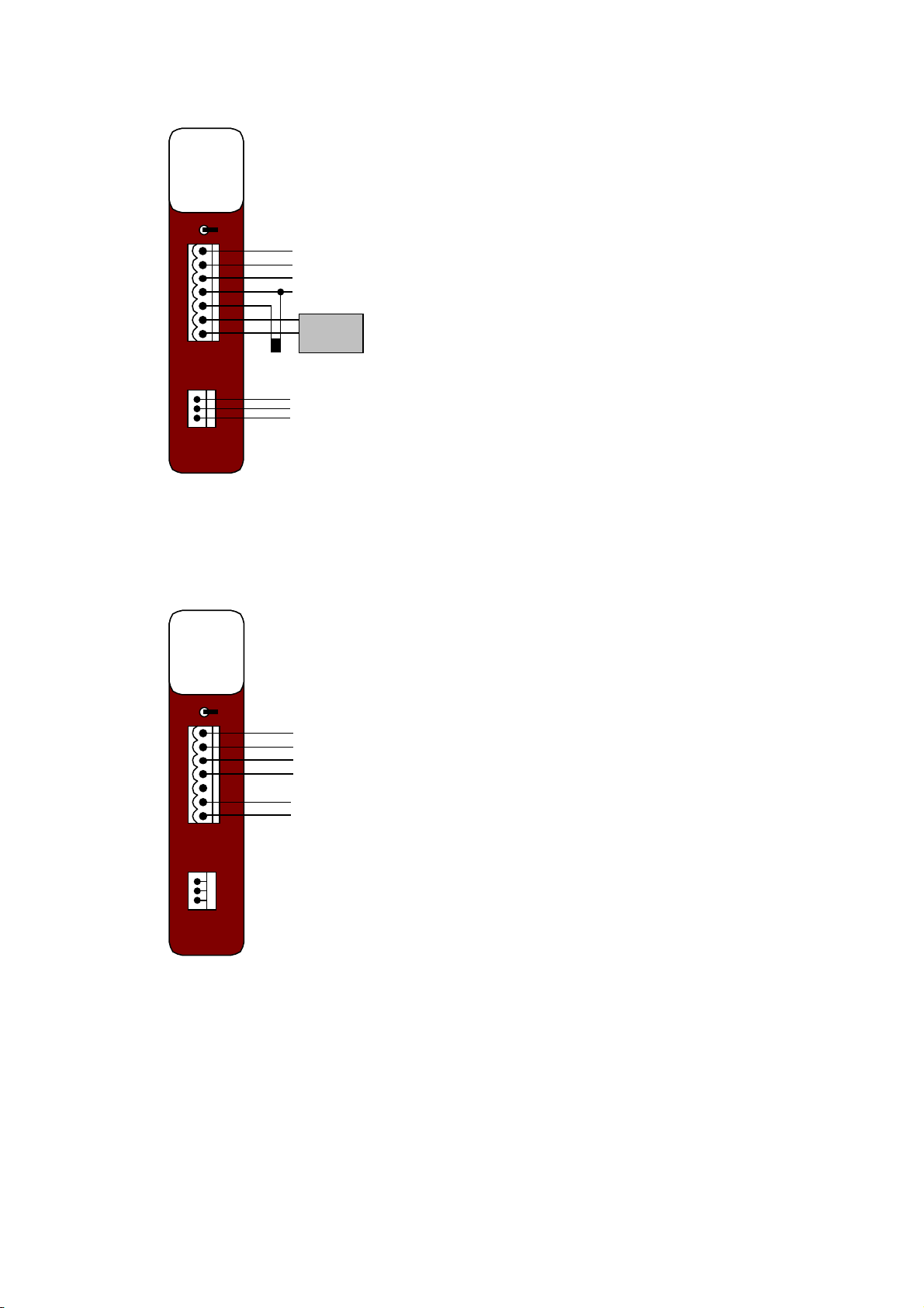
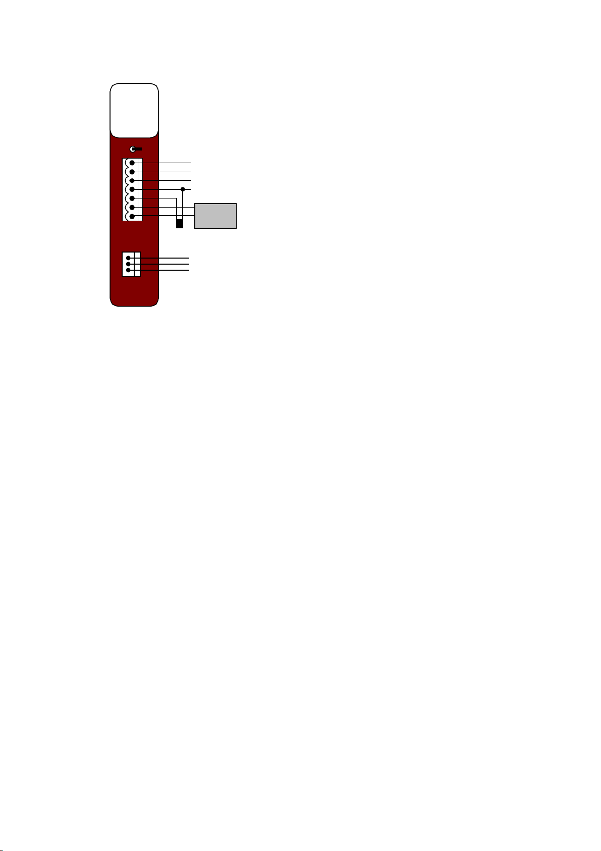
PS-1 Wiring Diagram – AC Supply
+
-
PS-1
OFF
E
N
A
+
-
24 VDC AUX. OUTPUT (OPTIONAL)
LOW POWER DC OUTPUT
(FOR RADIO OR OTHER DEVICE)
BATTERY
TEMP.
SENSOR
NEUTRAL
+
-
TAPE TEMPERATURE SENSOR
TO NEGATIVE BATTERY
TERMINAL. CONNECT BLACK
STRIPED WIRE OF SENSOR TO
R- OR B-
90-250 VAC INPUT SUPPLY
VA+
VA-
R+
R-
TS
B+
B-
ACTIV E
EARTH

Superseded Hardware Manual 7.12
www.cse-semaphore.com/mykingfisher
Page 12
PS-1 Wiring Diagram – DC Supply
The battery input of the PS-1 can also be used as a DC supply input. The following diagram shows
how the PS-1 is wired for a DC supply.
+
-
PS-1
OFF
E
N
A
+
-
24 VDC AUX. OUTPUT (OPTIONAL)
DC OUTPUT
(FOR RADIO OR OTHER DEVICE)
+
-
VA+
VA-
R+
R-
TS
B+
B-
NOT
CONNECTED
11.8 TO 14.0 VDC SUPPLY
(MUST BE ISOLATED FROM FIELD
SUPPLY)

Superseded Hardware Manual 7.12
www.cse-semaphore.com/mykingfisher
Page 13
1.2 PS-10: AC SupplyInput 90 to 260 VAC
& PS-20: DC Supply Input 20 to 60 VDC
The PS-10 power supply provides AC to DC conversion, DC voltages for the backplane, battery and
radio (or an external device), an optional isolated 24 VDC output and an optional monitoring
processor. The PS-20 power supply offers the same functionality as the PS-10 except it has a DC
supply input instead of an AC supply input.
The PS-10 and PS-20 are manufactured to power a 12 V backplane, 12 V battery and 12 V radio. The
PS-10 and PS-20 are available as a 24 V module by special order (please see below for
specifications).
An isolated 24 VDC output rated at 10 W (400 mA) is an option available for powering a limited
number of analog loops or digit input circuits. It cannot be used with inductive loads such as coils,
contactors etc. Power for these is to be provided from a separate supply.
In addition the module has limited charging capacity for externally connected lead acid batteries. The
temperature compensated charging capacity is designed for float operation and short term boost of
batteries already charged and in good condition. Use of this supply on flat or fully discharged batteries
may cause damage.
When the AC supply fails and the system is powered from external lead acid batteries (if connected),
the voltage monitoring circuit provides battery cut-off (for battery preservation) when battery cell
voltage drops to 10.5 V ± 0.2 V.
The PS-10/20 has an optional monitoring processor that can be factory fitted. This allows battery
voltage, battery current, regulated supply current, and internal or external temperature to be
monitored.
If no monitoring circuit is loaded, the PS-10/PS-20 will not be able to communicate with the processor
module and therefore will not show up in the hardware overview. In addition, there will be no power
supply monitoring information (i.e. indication of battery current, battery voltage, temperature, battery
low, AC present, Aux 24 V present) in the system. On/off control of the radio power and auxiliary 24 V
output power will be under control of the processor module.
A power supply module can be installed in any I/O slot of a 3, 6 or 12 slot backplane in a system. Up
to 4 Power Supply modules of any type can be installed on a backplane thus providing redundant and
alternative power source configurations.
Part numbers:
PS-10-CU, PS-20-CU
‘C’= Auxiliary 24 V DC to DC converter fitted. ‘0’=Not fitted.
‘U’= Power supply monitoring processor fitted. ‘0’=Not fitted.

Superseded Hardware Manual 7.12
www.cse-semaphore.com/mykingfisher
Page 14
PS-10/PS-20 – Standard Specifications
Input Supply 90 to 260 VAC 50/60 Hz (PS-10)
+20 to +60 VDC or –20 to –60 VDC (PS-20)
Note: the module can also be powered using 12 to 13.8 VDC when
powered from the backup battery terminals.
Backup Battery 12 VDC, 26 AH max. Sealed Lead-Acid
Outputs +5 VDC @ 2 A Max. to Bus
+12 VDC @ 4 A Max. to Bus
+12 VDC @ 4 A Max. to Battery
+24 VDC Isolated @ 400 mA Max. to Field (optional)
+13.8 VDC @ 3.6 A Max. to Radio
Maximum output power: 50 W
Isolation 3 kV AC input/DC output
3 kV Isolated 24 VDC output
Deep Discharge
Protection RTU Shutdown at 10.5 V + 0.2 V
RTU Startup at 11.8 V +0.2 V
Supply Fuse Slow blow internal
1.6 A (PS-10) or 6.3 A (PS-20)
Battery Fuse 4 A Polyfuse (self-resetting)
Connector Removable for AC/DC connections
LED indicators
(Standard) Vsup DC voltage present
Vb Battery voltage present
5 V 5 V present
Vaux Auxiliary converter present
Monitoring Processor
(Optional) Monitoring Circuits:
Battery Current
Battery Voltage *
Supply Current *
Temperature
Detection circuits:
AC present
Battery low
Aux. 24 V present
Control circuits:
Aux. 24 V on/off
Radio power on/off
LED indicators:
OK Microprocessor Watchdog
Batt CHG Battery Charging
FL Float Charge
BO Boost Charge
LO Battery Low
* The battery voltage is monitored when the input supply is disconnected. While the input supply is
connected, the module will measure the regulated voltage and current output of its AC (PS-10) or DC
(PS-20) input circuit.

Superseded Hardware Manual 7.12
www.cse-semaphore.com/mykingfisher
Page 15
PS-10-2/PS-20-2 – 24 V Specifications
The 24 V power supply has the same specifications as the 12 V power supply (PS-10-1, PS-20-1)
except it supplies 24 VDC to the backplane, battery and radio as detailed below.
Outputs
+5 VDC @ 2 A to Bus
+24 VDC @ 2 A Max. to Bus
+24 VDC @ 2 A Max. to Battery
+24 VDC Isolated @ 400 mA to Field (optional)
+27.6 VDC @ 1.8 A to Radio
Maximum output power: 50 W
PS-10/PS-20 – Block Diagram
NFILTER
RECTIFIER
A
E
LED
VSUP
TEMPERATURE
COMPENSATION INTERNAL
TEMP.
SENSOR
TS
R-
EXT.
TEMP.
SENSOR B+
B-
OPTIONAL
BATTERY
+5V
REGULATOR
50 W
DC/DC
CONV.
Vb
5 V
0V
PCON
EARTH
LOW
VOLTAGE
CUTOFF S1 LED
Vb
BACKPLANE
LOW
VOLTAGE
MONITOR
LED
LO
MICROCONTROLLER
RS485
DRIVER
LED
OK LED
CHG LED
BO LED
FL
BACKPLANE
ISOLATED
24V AUX.
DC/DC
CONVERTER
10 W
(OPTIONAL)
LED
VAUX VA+
VA-
R+
R-
RADIO
LK4
LK5
Vb
RADIO
POWER
AUX24 PWR
IsupCURRENT
MONITOR
Ibat CURRENT
MONITOR
PWR TEMP Ibat Isup
BAT LOW
OPTIONAL
MONITORING

Superseded Hardware Manual 7.12
www.cse-semaphore.com/mykingfisher
Page 16
PS-10/PS-20 – Module LEDs
LED Description (when ON)
OK * Module is functioning OK
Vsup AC supply input is powered. For PS-20, ON when DC input circuitry is powered.
Vb Battery voltage supply is OK. This LED should always be on and means that the power
supply is able to charge a battery or is being powered by the battery input.
5 V Internal 5 V supply is OK. This LED should always be on as the 5 V supply is used to
power all the modules.
Vaux Auxiliary 24 V supply is OK (will only display if the 24 V converter is installed).
Controllable if a monitoring processor is fitted.
BATT CHG * Battery is being charged
FL * Battery is in float charge mode
BO * Battery is in boost charge mode
LO *
Battery has reached discharged condition (< 11.5 V± 0.2 V).
LO LED is cleared when battery > 12.4 V ± 0.2 V
* Only enabled when a monitoring processor is fitted (optional for the PS-10 and PS-20)
PS-10/PS-20 - AdditionalFeatures
The PS-10 and PS-20 have an additional DC output for powering low power radios. The connections
are on the DC terminal block. This output is switched off on low battery voltage for battery protection
and can be controlled when the monitoring processor is fitted.
The PS-10/PS-20 is supplied with an internal and external temperature sensor. When a battery is
connected, the external sensor should be mounted close to the negative terminal of the battery to
ensure correct charging operation. The lowest temperature is monitored by the monitoring processor
and used by the temperature compensated battery charging (in normal operation the internal
temperature sensor will indicate a higher temperature than the external sensor).
Superseded Hardware Manual 7.12
www.cse-semaphore.com/mykingfisher
Page 17
PS-10 Wiring Diagram – AC Supply
+
-
PS-10
OFF
+
-
24 VDC AUX. (OPTIONAL)
13.8 VDC (FOR RADIO
OR OTHER DEVICE)
BATTERY
TEMP.
SENSOR
+
-
TAPE TEMPERATURE SENSOR
TO NEGATIVE BATTERY
TERMINAL. CONNECT BLACK
STRIPED WIRE OF SENSOR TO
R- OR B-
VA+
VA-
R+
R-
TS
B+
B-
E
N
A
90-260 VAC
NEUTRAL
ACTIV E
EARTH
PS-10 Wiring Diagram – DC Supply
The battery input of the PS-10 can be used as a DC supply input.
VA+
VA-
R+
R-
TS
B+
B-
+
-
PS-10
OFF
+
-
24 VDC AUX. (OPTIONAL)
13.8 VDC (FOR RADIO
OR OTHER DEVICE)
NOT
CONNECTED
+
-
11.8 TO 14.0 VDC SUPPLY
(MUST BE ISOLATED FROM FIELD
SUPPLY)
E
N
A
Superseded Hardware Manual 7.12
www.cse-semaphore.com/mykingfisher
Page 18
PS-20 Wiring Diagram
+
-
PS-20
OFF
E
-
+
+
-
24 VDC AUX. OUTPUT (OPTIONAL)
13.8 VDC OUTPUT
(FOR RADIO OR OTHER DEVICE)
BATTERY
TEMP.
SENSOR
+
-
TAPE TEMPERATURE SENSOR
TO NEGATIVE BATTERY
TERMINAL. CONNECT BLACK
STRIPED WIRE OF SENSOR TO
R- OR B-
20-60 VDC INPUT SUPPLY *
VA+
VA-
R+
R-
TS
B+
B-
-SUPPLY
+ SUPPLY
EARTH
*A NEGATIVE DC INPUT SUPPLY CAN BE USED.
CONNECTTHE MORE POSITIVE WIRE
(eg 0 V) TO +SUPPLY AND CONNECT THE MORE
NEGATIVE WIRE (eg -48 V) TO -SUPPLY.

Superseded Hardware Manual 7.12
www.cse-semaphore.com/mykingfisher
Page 19
1.3 PSU-2: DC SupplyInput, 18 to 36 VDC
The PSU-2 DC supply (18 to 36VDC) module provides DC to DC conversion, galvanic isolation,
+12 VDC, +5 VDC and various monitoring functions to power the RTU modules.
An isolated 24 VDC output rated at 10 W (400 mA) is available for powering a limited number of
analog loops or digit input circuits. It cannot be used with inductive loads such as coils, contactors etc.
Power for these is to be provided from a separate supply.
The PSU-2 features optional supply, voltage, current and temperature monitoring circuits that enable
the processor unit to access these as analog and digital points in the system. When the DC supply
fails and the system is powered from external lead acid batteries if connected the voltage monitoring
circuit provides battery cut-off (for battery preservation) when battery cell voltage reaches 10.5 VDC.
The load capacities for each output of the power supply are shown in the following table. Note: the
specifications shown are for the 12 V model of the PSU-2. The PSU-2 was also available as a 24 V
model.
PSU-2 Specifications
Input Supply 18 to 36 VDC Nominally 24 VDC
Outputs +5 VDC @ <10 W to Bus
+12 VDC @ <50 W to Bus
+12 VDC @ <50 W to Battery
+24 VDC Isolated @ 10 W to Field
Total 50 W max.
Isolation 2.5 kV DC input/DC output
2.5 kV Isolated 24 VDC output
Deep Discharge Protection RTU Shutdown at 10.5 V
RTU Startup at 11.8 V
Supply Fuse 4 A slow blow internal
Monitoring Circuits Battery Current and Voltage, Temperature, DC
Supply
Status Indicators Supplies and Battery on Front Bezel
Connector Removable for DC connectors

Superseded Hardware Manual 7.12
www.cse-semaphore.com/mykingfisher
Page 20
PSU-2 Block Diagram
+
FILTER
-
E
B+
B- OPTIONAL
BATTERY
+ 5 V
REGULATOR
50W
DC/DC
CONVERTER
+ 12V
5V
0V
EARTH
ON/OFF
BACKPLANE
80C51 MICRO
CONTRO LLER RS485
DRIVER
10W DC/DC
CONVERTER
VA+
VA-
+ 24V
ISOLATED
OUTPUT
ON/OFF BATTERY
C UT O FF
SERIAL BUS
LED DISPLAY
MONITORING
MODULE
ADC 8 BIT
TEMP.
SENSOR
V
I
Vs
PSU-2 Module LEDs
Three red LEDs labelled +5 V, +12 V and Vs are on when the various power supply sections are
functioning correctly. The Vs LED indicates when the isolated 24 Volt/10 Watt output is activated. This
output is under the main processor control (CP-1 or SBX-2) but is normally in the on state. A green
LED at the top of the face plate is ON when the microcontroller of the monitoring circuit and the power
conversion circuits are operating correctly. An additional four red LEDs labelled CHG, FL, BO and LO
indicate the condition of a connected battery which are:
CHG Battery is being charged
FL Battery is in float charge mode
BO Battery is in boost charge mode
LO Battery has reached its discharged condition (<22 V)
This module can be installed in any I/O slot of a 3, 6 or 12 slot backplane in a system. Up to 4 Power
Supply modules of any type can be installed in a backplane thus providing redundant and alternative
power source configurations.
This manual suits for next models
2
Table of contents
Popular Industrial Equipment manuals by other brands


Genie
Genie RAIL EXTENSION KIT Supplement Instructions

Panasonic
Panasonic Aicure UD40 Series user manual

DEPURECO
DEPURECO ECOBULL Instruction and maintenance manual

Carlisle Fluid Technologies
Carlisle Fluid Technologies Ransburg AER4006-01 Service manual

Labelmate
Labelmate S-100-SP quick start guide

Colli FGB
Colli FGB GP20 user manual