I-UM_5
REV_A
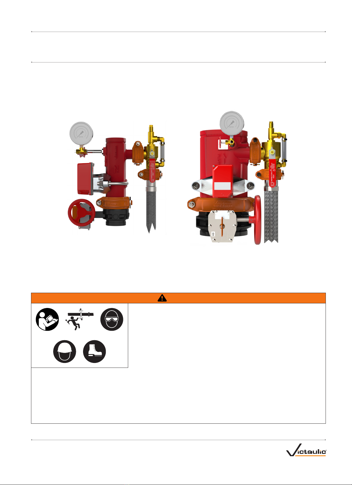
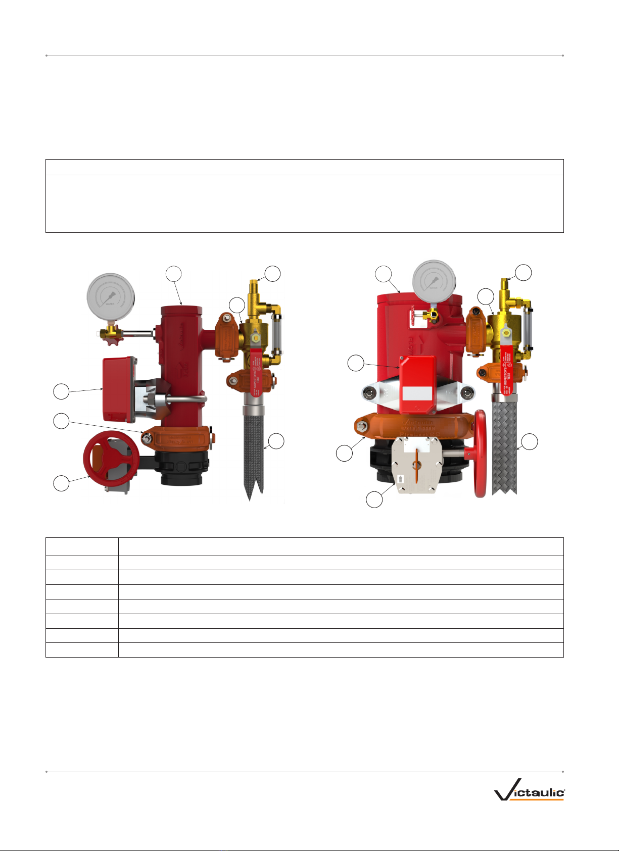
I-UM / Series UM Universal Manifold Assembly / Installation, Maintenance, Inspection, and Testing Instructions
TESTING
Refer to NFPA 25, FM Datasheets, or any applicable local requirements to perform testing. The authority having jurisdiction in the area may require
these tests on a more frequent basis. Verify these requirements by contacting the authority having jurisdiction in the affected area.
Before proceeding with any tests involving water flow, the following precautions shall be taken.
NOTE: It is not necessary to remove the ARV to perform a hydrostatic test. The ARV may be adjusted temporarily to a pressure above the test
pressure. Verify that the ARV is returned to its normal setting after completing the hydrostatic test.
1. Check for alarm connections to a central station or fire department. If such connections are found, notify the authority having jurisdiction,
remote station alarm monitors, and those in the affected area before proceeding with testing. NOTE: A main drain test may also operate local
fire alarms, unless they are temporarily disabled.
2. Check the location where the test connection discharges to verify that all is clear and that there is no possibility of water flow causing property
damage or personal injury.
3. Check the end of the test connection to verify that it is unobstructed. To achieve a satisfactory test, there shall be an unrestricted flow of water
when the handle on the UTD is in the “DRAIN” (full drain) position.
4. Move the handle on the UTD to the “TEST” (flow through K-factor orifice) position. Verify that an alarm condition results within the timeframe
specified by the local authority having jurisdiction.
5. Move the handle on the UTD to the “OFF” (normal operating) position. NOTE: The ARV is located on the upstream side of the UTD and will
continue to vent excess system pressure with the handle on the UTD in the “OFF” (normal operating) position.
REQUIRED INSPECTIONS AND/OR MAINTENANCE
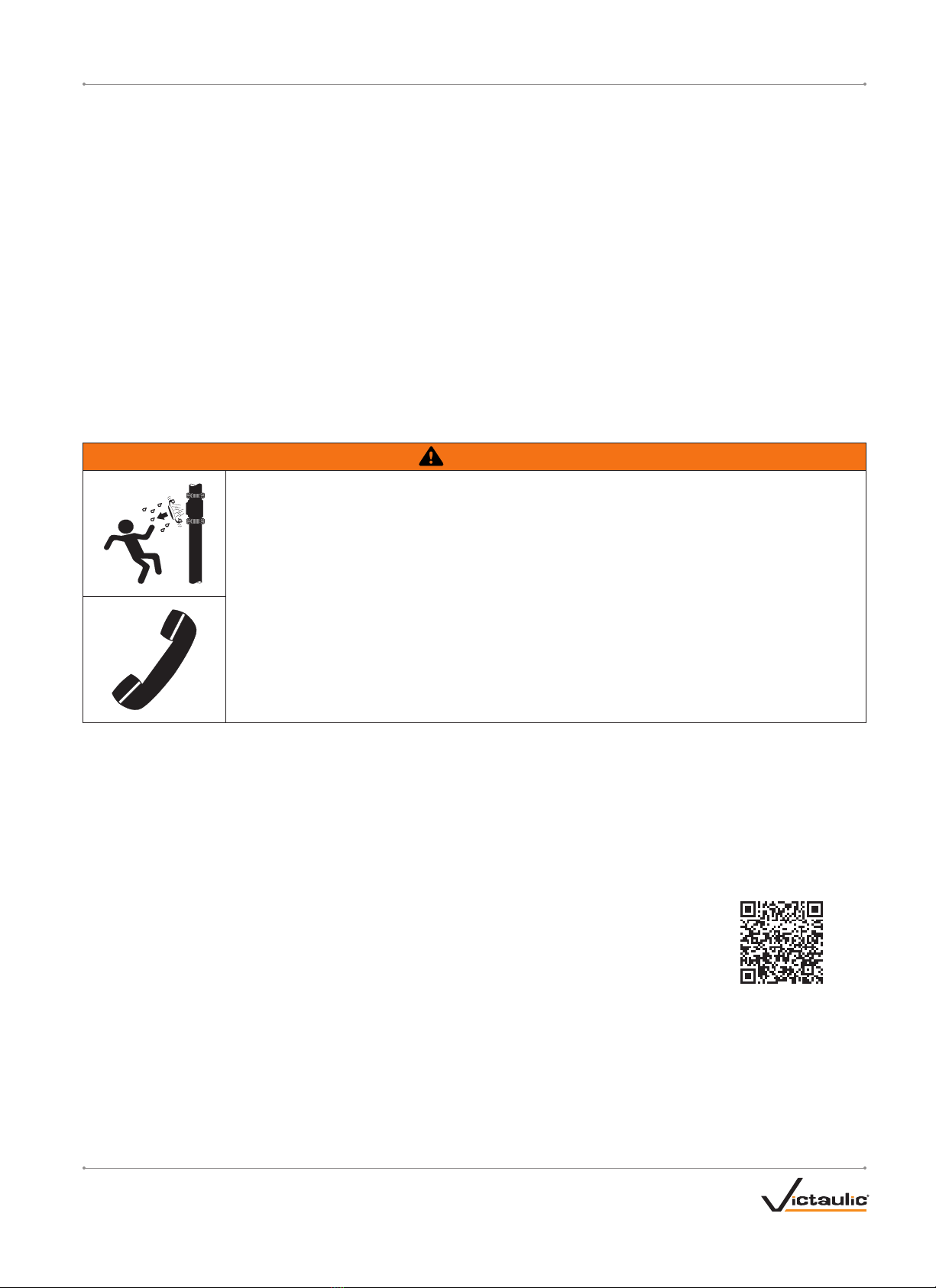
WARNING
• Depressurize and drain the piping system before attempting to perform any maintenance.
• The building owner or their representative is responsible for maintaining the fire protection system in proper
operating condition.
• To ensure proper system operation, refer to NFPA 25, FM Datasheets, or any applicable local requirements for
valve inspection requirements. The authority having jurisdiction in the area may require these inspections on a
more frequent basis. Verify these requirements by contacting the authority having jurisdiction in the affected
area, and always refer to the instructions in this manual for additional inspection and testing requirements.
• The frequency of inspections shall be increased in the presence of contaminated water supplies, corrosive/scaling
water supplies, and corrosive atmospheres.
• Any activities that require taking the valve out of service may eliminate the fire protection provided. A fire patrol
is strongly recommended for the affected areas.
• Before servicing or testing the system, notify the authority having jurisdiction.
Failure to follow these instructions could cause system failure, resulting in death or serious personal injury and
property damage.
Refer to NFPA 25, FM Datasheets, or any applicable local requirements to perform inspections and/or maintenance. The authority having jurisdiction
in the area may require inspections and/or maintenance on a more frequent basis. Verify these requirements by contacting the authority having
jurisdiction in the affected area.
1. Notify the authority having jurisdiction, remote station alarm monitors, and those in the affected area before performing any inspections, testing,
or maintenance that requires closing the control valve.
2. Verify that the system is completely depressurized and drained immediately prior to performing maintenance. NOTE: Keep the handle on the
UTD in the “DRAIN” (full drain) position during any maintenance.
3. The water supply shall be free from sediment or other debris. During an inspection of a water control valve, if sediment or other debris is noted,
a further examination of internal valve parts is required. Remove all deposits from all operating components and ports.
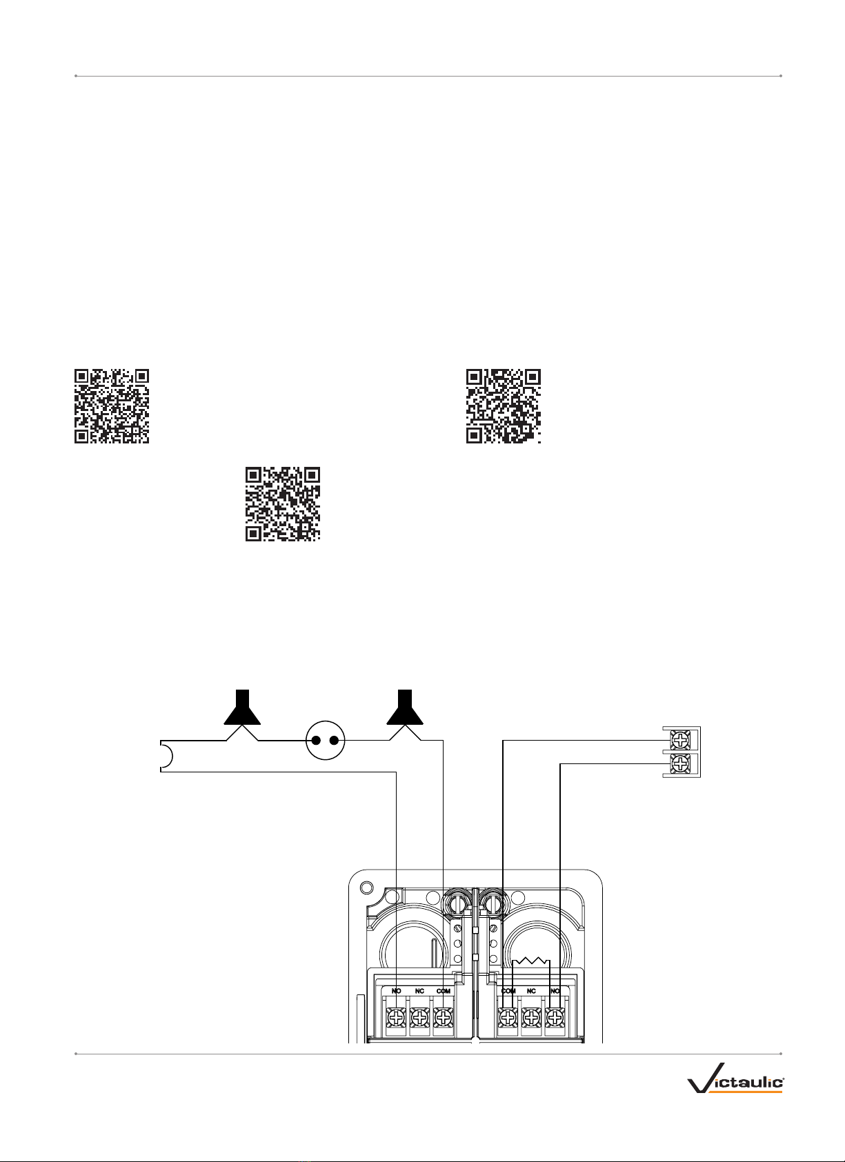
Flow Switch (All Sizes):
Periodic testing and inspection is required for the flow switch. Scan the QR code provided for complete flow switch
and paddle replacement instructions.
Scan QR code for flow switch
used on all UM sizes
ARV (All Sizes): The ARV is not field serviceable. If leakage is observed, test the pressure setting by referring to the “ARV Setting Procedure.” The
ARV shall be replaced if it does not respond to field adjustments. NOTE: Visual calibration lines on the ARV are used for approximate adjustment.
Verify the pressure setting with a calibrated pressure gauge.
UTD (All Sizes): The UTD does not require any regularly scheduled maintenance and is not field serviceable.