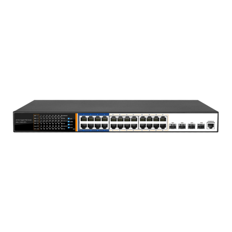
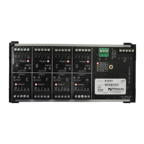
Mi NPM-R10 SNMP User manual

1 | P a g e
Network Power Monitor R10 SNMP
Mi
Innovative Electronics for a Changing World
NPM-R10 Remote Network Power Monitor
With optional relay board and GSM module
INDEX
1.
SYSTEM ESCRIPTION
2.
BOAR CONNECTIONS terminals and indicators
3.
CONNECTION IAGRAM
4.
5 Relay board - expansion board
5.
GSM module and functions
6.
START UP GUI E and passwords
7.
HOME PAGE
8.
STATUS PAGE
9.
RELAY CONTROL PAGE
10.
NETWORK CONFIGURATION PAGE
11.
TFTP Boot-loader – firmware upgrade via Ethernet
12.
Mi SNMP Manager setup
13.
SNMP Configuration for the ude
14.
Physical dimensions
Network Based Remote Power Monitor

2 | P a g e
Network Power Monitor R10 SNMP
Mi
NPM-R10 SNMP – DC - dual current sens r / Charge + L ad current 50 Amp
is lated
Factory Reset switch - behind LC there is a hole in the casing– insert a thin plastic object –
push the internal reset switch or short the two pcb pins and power up the unit, the unit will
start with the display indicating some text, keep the switch pressed and wait about 10sec
until the LC display goes blank, keep another 5 seconds and release the switch – the unit
will reboot and the default IP will be loaded.
Default IP address: 192.168.1.2
1. SYSTEM DESCRIPTION
Main Unit
Relay Board optional) GSM Board optional)

3 | P a g e
Network Power Monitor R10 SNMP
Mi
The NPM-R10 (NETWORK POWER MONITOR R10) was designed to assist Network
and Wireless Network specialists with Power related information via Ethernet and
GSM Communication.
Total Battery Voltage as well as separate Battery voltages for series connected
Battery banks, Charging Current, Load current to equipment, Mains 220Vac Status,
1x External 100Vdc input , Alarm input and temperature information is available via
web pages, SMS and SNMP.
Embedded Web pages for monitoring and configuration of the system.
The unit supports the SNMP V1 and SNMP V2C communication platform to be
compatible with SNMP monitoring software platforms.
The NPM-R10 is powered by C language firmware and the code was written to
function as a co-operative RTOS.(Real time operating system)
2x16 LC display onboard for quick access and indication of power related
information on site
Indicating :
(B:) Total Battery pack voltage
(Mains :) ON or OFF
(I:) Charge current
(i:) Load current - in case of alarm active (i:) will be replaced with (AL) for Alarm

4 | P a g e
Network Power Monitor R10 SNMP
Mi
2. BOARD CONNECTIONS
The NPM-R10 can w rk fr m a single 12V , 24V , 36V r 48V system
Wiring between batteries if m re than 1 Battery can be a large gauge and is
cust mer defined by the am unt f amps required by the charger and l ad
system
The wiring fr m – (gr und) and each batteries + (p sitive) t the NPM-R10 can
be a small (thin) gauge wire as the NPM-R10 d es n t c nsume large currents
and nly sense the battery v ltages fr m here
Current c nsumpti n in t tal with LAN p rt c nnected 110mA @ 12Vcdc / 55mA
@ 24Vdc

5 | P a g e
Network Power Monitor R10 SNMP
Mi
3.
C nnecti ns. (Imp rtant Please Read)
C nnect GND (-) f the Battery system t the left hand side terminal marked
“GND”
The system will perate fr m 12 , 24 , 36 r 48V battery v ltages
C nnect the first battery (+12v) f the pack t Terminal “ 12+”
C nnect the sec nd Battery if 24V system (+24v) t Terminal “24+”
C nnect the Third battery if 36V system(+36v) f the pack t Terminal “ 36+”
C nnect the F urth Battery if 48v system (+48v) t Terminal “48+”
The 12+ up to 48+ wires and the GN wire can be thin eg. 0.5mm wires as the current
consumption of the device is low.
Thick wires should be used for charge current and load current feed through depending on
the current requirement of your equipment.
Connect The Charger + to the Charge terminal marked “Charger+ IN”
Connect the terminal marked “+Charger out” to your battery pack main +
External Temperature sensor can be extended away from the board with 3 wires – range : -
10 to +125 eg C
**** IMPORTANT NOTE****
The Alarm input is a potential free contact input only and NO
voltages should be injected here- Permanent amage to the
unit will occur.

6 | P a g e
Network Power Monitor R10 SNMP
Mi
The current feed through for “LOA ” current and Charge current is two isolated
current ports. +Charge out can be bridged as above to + Load in as both comes
from the Battery pack main +
V1 External Vdc input can be used to monitor eg. Output of C- C converters or the
output voltages from Solar Panels etc.
The external 0-100 Vdc input is polarity protected on the board and the customer
can wired + and – for the input in any way.
The input is protected by a 110V TVS diode for spikes and over voltage
The Battery power input , 0-100V C external input and the 220Vac Mains input is
surge and over voltage protected.
After the Alarm is triggered the (i:) indication of the Load current in the bottom right
corner of the LC will change to AL: to indicate the Alarm condition.
The Alarm SNMP (OI ) data will change from a 0 to a 1 , as soon as the Alarm input
is restored the screen will be cleared from AL: for alarm and return to i: for Load
current indication but the Alarm SNMP OI will stay at data 1 for about 20 sec after
the alarm was cleared.
This is working well with PIR alarm detectors etc so that the alarm condition is not
missed by the SNMP manager software

7 | P a g e
Network Power Monitor R10 SNMP
Mi
Connection Examples:

8 | P a g e
Network Power Monitor R10 SNMP
Mi

9 | P a g e
Network Power Monitor R10 SNMP
Mi

10 | P a g e
Network Power Monitor R10 SNMP
Mi

11 | P a g e
Network Power Monitor R10 SNMP
Mi
4. Relay Expansion oard
The 5 Relay expansion board connects to the NPM-R10 via a 10way ribbon cable
supplied with the relay board
Relay 1,2,3 can only be toggled to activate for 10sec then return to the off position
again and is used to reset devices.
Relay 4 and 5 can be controlled to the ON or OFF position by the user and will keep
the selected position until changed by the user.
The status of all 5 relays is displayed on the home page of the unit by means of
green dots
In the “Relay” control page the user can assign names to the relays to help
remember what is connected to the relays at the remote site.

12 | P a g e
Network Power Monitor R10 SNMP
Mi
5.
GSM m dule and functi ns
**FREE ANDROID APP TO DOWNLOAD ON THE GOOGLE PLAY STORE –
Search f r “Mi GSM c ntr ller”
The Android application makes it easy to save multiple cell numbers with user
defined names for each number
Also because relay wiring would not be the same at each site user defined names
can be saved to each relay in the app under each specific site
Select NPM R10 GSM in app for this model
The NPM-R10 GSM module interfaces to the main board via a 20way ribbon cable and no
other connections are necessary.
The 4 way dip switch on the printed circuit board allows the user with the following:
Switch 1 – (ON) – SMS will be send if mains fails and when mains returns
Switch1 – (OFF) – NO SMS will be send regarding mains status
Switch 2 – (ON) – SMS will be send if the Alarm input n the NPM-R10 main
b ard g es pen circuit
Switch2 – (OFF) – NO SMS will be send regarding Alarm status
Switch 3 – (ON) – SMS will be send if Battery v lts falls bel w a certain level,
Auto calculating (11.5V for 12v system)- (23.0V for a 24V system) – (33.5V for a 36V
system ) and (46.0V for a 48V system)
Switch 3 – (OFF) – NO SMS will be send regarding Battery status
Switch 4 – (ON) – SMS will include the status f Relay 4 and Relay 5 if n r ff
Switch 4 – (OFF) – SMS will n t include Relay status in the message
If all dip switches is to the on position on the GSM board the user(s)will automatically
receive a SMS in case of an Alarm, Mains failure and Battery low condition

13 | P a g e
Network Power Monitor R10 SNMP
Mi
Setup of GSM module
Insert a SIM card and install the reset jumper J5, p wer the NPM-R10
After about 10 sec remove the Reset jumper(all number cleared)
Notice the STATUS led will glow and the NETWORK led will flash at a fast rate
After about 8 sec if the unit finds a Network connection the NETWORK led will start to blink
Slowly, wait about 20 sec before sending an SMS
Send “Status?” from primary cell phone(or tap on Status in the app and then on the green
envelope symbol to send the command) – unit will save this number as the primary number and
return a Status sms to the phone – primary number can only be deleted by a hard reset with jumper
J5 again on power up
Send “Status?” from another number (or tap on Status in the app and then on the green envelope
symbol to send the command) at anytime, this will save the number as the secondary number and
return a status sms to this secondary number
Use the app t c ntr l the m dule with the c mmands available in the app.
Send “Clear” manually will delete the secondary number and a new secondary number can be added
by sending “Status?” again from a new number
____________________________________________________________________________
SMS C mmands with ut using the app :
Insert J5 and power the unit , wait 10sec and remove J5 – all numbers cleared now
Wait until Status led flash at a slow rate indicating the unit linked to a network
Wait another 10 seconds before sending a SMS again
Send “Status?” from the primary number
A status sms will be returned to the number – primary number saved now
Wait 10 sec
Send “Status?” from the secondary number
A status sms will be returned to the secondary number – secondary number saved now
***Send “Clear” will delete the secondary number and a new secondary number can be added by
sending “Status?” again from a new number
C mmands :
Send “SetRD1” to t ggle relay1 on the expansion board – after 8sec the relay will de-energize and
“Reset Successful” will be returned to the phone activating the command
Send “SetRD2” to t ggle relay2 on the expansion board – after 8sec the relay will de-energize and
“Reset Successful” will be returned to the phone activating the command
Send “SetRD3” to t ggle relay3 on the expansion board – after 8sec the relay will de-energize and
“Reset Successful” will be returned to the phone activating the command
Send “SetRD4” will set the Relay4 n the expansi n b ard t the n p siti n , a sms “ Relay
4 n” will be send to the originator
Send”SetRD4” again will switch the Relay4 n the expansi n b ard t ff p siti n, a sms
“Relay 4 off” will be send to originator
Send “SetRD5” will set the Relay5 n the expansi n b ard t the n p siti n , a sms “ Relay
5 n”will be send to the originator
Send”SetRD5” again will switch the Relay5 n the expansi n b ard t ff p siti n, a sms
“Relay 5off” will be send to originator

14 | P a g e
Network Power Monitor R10 SNMP
Mi
6. START UP
By default the unit is shipped with a default IP address of
192.168.1.2
Micro Instruments Network Power Monitor R10 will be displayed where
after the current TCPIP stack functions will be displayed.
192.168.1.2 appear on the LC as the default IP address or the user
defined IP if already configured.
Connect to the IP address via a web browser.
To Factory reset the unit, insert a small plastic object into the hole
behind the LC display in the casing , push the switch while board is
NOT powered, power the unit, isplay will show model number etc and
then go blank, keep switch another 5 seconds and the release , the
board is restored to factory settings. The unit will re-start with the
default configuration.
Micro Instruments registered private enterprise number (PEN) 45501
To login to the Relay control page , Network settings or SNMP configuration pages
the following passwords must be used.
Default : username = admin
Default Passw rd = admin
Login to the Network Configuration page : Password(max 10 characters) User
defined Password can be configured and click save
Username : admin
Password : xxxxx (user configured Password)
Please note the there is no backdoor for a forgotten Password and the board will
have to be reset to factory defaults

15 | P a g e
Network Power Monitor R10 SNMP
Mi
7. HOME PAGE
The Stack version is displayed, the build date of the firmware programmed on to the
device, the units serial number as well as the model number.
A visual indication of the status of Relays 5 to 1 is given and indicated by a green
dot if the relay is active (powered)
A “module heartbeat” indication by a green dot flashes once per second as the
software runs through the TCPIP applications.
Alarm – ON/OFF and Mains –ON/OFF is displayed
AJAX Browser code for Battery voltage measurements for quick updating of
displayed information .
Left hand menu will navigate to different applications on the unit.

16 | P a g e
Network Power Monitor R10 SNMP
Mi
8. STATUS PAGE
Manufacturing date and serial number is displayed.
External temperature sensor is displayed in degrees Celsius.
External Voltage input V1 is displayed as 0 to 100Vdc
Battery 1 t 4 V ltages is given separately fr m each ther - if all
c nnected
A reflection of the module’s LC display is captured and displayed on this page
Battery voltage , charge current , Mains status on or off and the Load current .

17 | P a g e
Network Power Monitor R10 SNMP
Mi
9. RELAY CONTROL PAGE
Admin and admin or admin and user defined password to access
Relay 5 and 4 can be controlled to the on/off status or SNMP “SET” commands and
will keep their positions, Relay 3 to 1 can only be toggled for 10 second periods and
is typically used to reset radios or routers without logging yourself out completely
from the remote site after a relay was accidently switched , relay 3 to 1 will return
automatically after 10 seconds to the off position. Names can be assigned to relays
to help the user remember what is connected to the relays in the field.

18 | P a g e
Network Power Monitor R10 SNMP
Mi
10. NETWORK CONFIGURATION PAGE
Admin and admin r admin and user defines Passw rd gains access
MAC address is displayed and cannot be changed
Host Name can be changed by the user to a new name
Setup IP address, Gateway and Subnet Mask
Save C nfigurati n – unit will reb t
After the configuration was saved the “ Reboot in Progress” page will load
The unit will reboot and configure and should be live in about 5 seconds

19 | P a g e
Network Power Monitor R10 SNMP
Mi
11.TFTP Boot-loader
PM-R10 supports TFTP Boot-loader for upgrading device software
remotely over a network.
The MAC address of the unit is hard coded into software for safety reasons
so first obtain a .hex file from us for the specific unit before attempting
TFTP.
Use TFTP file up-loader downloadable from our website
If TFTP is not a recognized command pops up , meaning Windows have
removed TFTP function from windows however it is still visible under
Windows services
Then please download TFTP up-loader for Win10
The user can TFTP to the units current IP address while running or to the
private IP address 192.168.97.60 in the first 5 seconds from powering the
board.
A TFTP session can also be initiated while the unit is in run mode to the
current configured IP address of the unit.
Should the user also have to re-load the webpage files obtained from us
Enter into a web Browser ( if default IP address – or enter current IP address
of the board)
http://192.168.1.2 /mpfsupload
a window will appear in the browser giving the user the option to browse for
the web page files and to upload them to the PM-R10 internal memory .

20 | P a g e
Network Power Monitor R10 SNMP
Mi
12.
SNMP Configuration
admin and admin r admin and user defined Passw rd gains access.
Configure read and write communities
Write communities is functional on the device via SNMP SET and GET functions but
is beyond the scope of this user manual as the relay’s can also be controlled via the
relay control page.
This can usually be left unaltered.
Table of contents
