Micha Solar MSR2-30 User manual

MSR2-30 Charge Controller
Product Manual
Issue 9

Micha Solar MSR2-30 Charge Controller 800817-9.doc
Product Manual
Page 2 of 23 Document: 800817-9.doc Date: September 2017 www.micha.co.uk
1. Introduction
The MSR2-30 Charge Controller provides the charge regulation and supervisory functions necessary in a solar
power system. The controller prevents damage to the battery due to excessive charge or discharge and also
provides a convenient place to interconnect the solar array, battery bank and load equipment.
The MSR2-30 Charge Controller has connections for two solar arrays, one battery and one load. The basic
function of the regulator is to control the transfer of energy from the array to the battery and load. The state of
charge of the battery is sensed by monitoring the battery voltage.
The MSR2-30 Charge Controller consits a Control Printed Circuit Board (PCB) Assembly which monitors the
battery state of charge and controls the state of the regulation devices and alarms. The optional LCD display
PCB Assembly mounts over and plugs into the main control board and enables the user to gain more
information on the controller status, and provides some test facilities.
1.1. Standard Features of the MSR2 Charge Controller
System Voltage: 12V, 24V and 48 versions
System Polarity: Positive Earth and Negative Earth versions
Microcontroller (MCU) based control circuit
Solid state switching of two array current inputs up to 15A each (total 30A)
Solid state switching of load current up to 15A
Temperature compensation of the preset levels
LED indication of Status, Disable, Array 1 Charging, Array 2 Charging and Load Connected
40A Battery Fuse and 20A Load Fuse as standard
10mm
2
cable entry for power cables
2.5mm
2
cable entry for signal cables
Protection against induced voltage transients
Small size Polycarbonate IP65 Enclosure (250x175x75mm)
High Volts, Low Volts, Load Cut and Auxiliary Alarm (indication and volt-free relay contact)
1.2. Optional Features of the MSR2 Charge Controller
MSR2-30 Metering: 2x16 Character LCD Display Unit for system parameter indication and control
MSR2-30 RS232 Communications Port to interface to a local PC – Normal or Modbus ASCII Protocols
2. Health & Safety
2.1. General
Read this manual thoroughly BEFORE undertaking any work.
Potentially lethal voltages can be present at the terminals within the Unit. Extreme care MUST be taken
when performing any of the actions described in this manual. Remove all metallic personal adornments
from the hands, wrists and neck before commencing work on a live unit. Ensure all tools are insulated.
2.2. Earthing
The MSR2-30 Charge Controller can be used with either a Positive Earth (Common Positive) or Negative
Earth (Common Negative) solar system.

Micha Solar MSR2-30 Charge Controller 800817-9.doc
Product Manual
Page 3 of 23 Document: 800817-9.doc Date: September 2017 www.micha.co.uk
3. MSR2-30 Control Unit Operation
3.1. Analogue Measurements
The MCU uses an A/D converter to read the battery voltage, the array voltages, the temperature sensor
and the array and load current if the metering option is included.
The battery voltage is read every 50ms (20 times a second). Where the unit determines a change of
mode or alarm status is necessary, four successive readings will have to be above or below the
appropriate setpoint (the exception is the High Volts Alarm) for the change to occur.
To obtain the true array voltages, the MCU needs to first disconnect an array from the battery (if
connected) and then read the array voltage. This is done approximately every 60 seconds
The temperature sensor is used to compensate the battery voltage. If faulty or disconnected, then the A/D
converter will return a value outside of possible air temperature limits in which case the regulator will
operate as if the temperature was sensed as being the Temperature Compensation Null Temperature (i.e.
zero compensation applied).
3.2. Battery Regulation
If the compensated battery voltage is less than the Reset-to-Boost voltage, the unit will enter the Boost
Mode. During this time the unit will connect the arrays to the battery if the voltage present on each array is
greater than the battery voltage by 2V. If the total array current is greater than the load current, the battery
will charge and the battery voltage will increase.
When the compensated battery voltage reaches the Boost voltage, the unit will enter the Equalisation
Mode. In this mode, the unit will disconnect and reconnect the arrays to the battery to regulate the battery
voltage at the Boost voltage for the Equalisation period. This ensures the battery reaches its optimum
state of charge.
After the Equalisation period, the unit will enter the Float Mode. In this mode, the unit will disconnect and
reconnect the arrays to the battery to regulate the compensated battery voltage at the Float voltage.
If the compensated battery voltage decreases below the Reset-to Boost voltage, the unit will enter the
Boost Mode.
When there is insufficient light to generate current (at night or on a day with poor light conditions), the
regulator disconnects the arrays from the battery to avoid the battery discharging back through the array.
This is the Night mode.
When the unit is regulating at either the Boost voltage or Float voltage, it will disconnect the arrays from
the battery when the battery reaches the required voltage. It will re-connect the array to the battery when
the compensated battery voltage falls below the required voltage by 0.15V(12V system), 0.3V (24V
system) or 0.6V (48V system).
3.3. Alarms Activation and Reset
If the compensated battery voltage is higher than the High Volts activation voltage, the array will be
immediately disconnected from the battery and the High Volts alarm relay and indicator will be activated.
If the compensated battery voltage is lower than the High Volts reset voltage, the High Volts alarm relay
and indicator will be immediately reset.
If the battery voltage is lower than the Low Volts activation voltage and remains lower for 2 seconds, the
Low Volts alarm relay and indicator will be activated. If the battery voltage is higher than the Low Volts
reset voltage, the Low Volts alarm relay and indicator will be immediately reset.
If the battery voltage is lower than the Load Cut activation voltage and remains lower for 2 seconds, the
Load Cut alarm relay and indicator will be activated. After the Load Cut switch delay period, the Load Cut
Switch and indicator will be activated. If the battery voltage is higher than the Load Cut reset voltage, the
Load Cut alarm relay and indicator and the Load Cut switch and indicator will be immediately reset.
If the voltage on either array does not exceed 2V above the Battery Voltage for a period of 24 hours then
the 24 Hour Alarm will be activated. The Auxiliary Alarm Relay can be programmed to activate for this
Alarm.
The Auxiliary Alarm Relay and indicator can be programmed (Menu 3) to activate on 24Hr Alarm,
Common Alarm (i.e. any alarm) or System Normal (i.e. active when they is no alarm). System Normal can
be used to ensure the charge controller is actually powered and operating correctly.

Micha Solar MSR2-30 Charge Controller 800817-9.doc
Product Manual
Page 4 of 23 Document: 800817-9.doc Date: September 2017 www.micha.co.uk
3.4. Status LED
A status LED is used to provide basic unit status to the user as described in the following table:
Mode Status LED Operation
Boost Mode Flash : 0.35 sec on - 0.35 sec off
Equalisation Mode Flash : 1.05 sec on – 0.35 sec off
Float Mode Steady
Night Mode Flash: 0.35 sec on – 2.45 sec off
3.5. Enable/Disable Jumper Link LK2
The Enable/Disable Jumper Link LK2 is used to Disable the Charge Controller. When the unit is Disabled,
the Arrays and Load are disconnected from the Battery. The unit must be Disabled inorder to enter the
Change Setting Menus (see Section 3.19).
3.6. Default Values 1 Setpoints – Fulmen
The setpoints for Fulmen Battey Cells and the operating parameters of the unit which are held in the
Microcontroller are listed in the following table:
Set-points – Fulmen Cells Volts / Cell 12V System 24V System 48V System
Boost & Equal Regulation Voltage 2.45 V 14.70 29.40 58.80
Float Regulation Voltage 2.30 V 13.80 27.60 55.20
Reset to Boost 2.20 V 13.20 26.40 52.80
High Volts Alarm Trip 2.50 V 15.00 30.00 60.00
High Volts Alarm Reset 2.30 V 13.80 27.60 55.20
Low Volts Alarm Trip 1.95 V 11.70 23.40 46.80
Low Volts Alarm Reset 2.30 V 13.80 27.60 55.20
Load Cut Alarm Trip 1.85 V 11.10 22.20 44.40
Load Cut Alarm Reset 2.10 V 12.60 25.20 50.40
Load Cut Switch Delay N/A 5 seconds 5 seconds 5 seconds
Equalisation Period N/A 30 minutes 30 minutes 30 minutes
Temp Compensation Null Temp N/A 20°C 20°C 20°C
Temp Compensation Rate N/A -5mV/ °C
/cell
-5mV/ °C
/cell
-5mV/ °C
/cell

Micha Solar MSR2-30 Charge Controller 800817-9.doc
Product Manual
Page 5 of 23 Document: 800817-9.doc Date: September 2017 www.micha.co.uk
3.7. Default Values 2 Setpoints – Vented
The setpoints for Vented Battey Cells and the operating parameters of the unit which are held in the
Microcontroller are listed in the following table:
Set-points – Vented Cells Volts / Cell 12V System 24V System 48V System
Boost & Equal Regulation Voltage 2.40 V 14.40 28.80 57.60
Float Regulation Voltage 2.35 V 14.10 28.20 56.40
Reset to Boost 2.20 V 13.20 26.40 52.80
High Volts Alarm Trip 2.45 V 14.70 29.40 58.80
High Volts Alarm Reset 2.40 V 14.40 28.80 57.60
Low Volts Alarm Trip 1.90 V 11.40 22.80 45.60
Low Volts Alarm Reset 2.00 V 12.00 24.00 48.00
Load Cut Alarm Trip 1.80 V 10.80 21.60 43.20
Load Cut Alarm Reset 2.00 V 12.00 24.00 48.00
Load Cut Switch Delay N/A 5 seconds 5 seconds 5 seconds
Equalisation Period N/A 30 minutes 30 minutes 30 minutes
Temp Compensation Null Temp N/A 25°C 25°C 25°C
Temp Compensation Rate N/A
-5.5mV/°C/cell -5.5mV/°C/cell -5.5mV/°C/cell
3.8. Default Values 3 Setpoints – VRLA
The setpoints for VRLA Battey Cells and the operating parameters of the unit which are held in the
Microcontroller are listed in the following table:
Set-points – VRLA Cells Volts / Cell 12V System 24V System 48V System
Boost & Equal Regulation Voltage 2.30 V 13.80 27.60 55.20
Float Regulation Voltage 2.25 V 13.50 27.00 54.00
Reset to Boost 2.10 V 12.60 25.20 50.40
High Volts Alarm Trip 2.40 V 14.40 28.80 57.60
High Volts Alarm Reset 2.35 V 14.10 28.20 56.40
Low Volts Alarm Trip 1.90 V 11.40 22.80 45.60
Low Volts Alarm Reset 2.00 V 12.00 24.00 48.00
Load Cut Alarm Trip 1.80 V 10.80 21.60 43.20
Load Cut Alarm Reset 2.00 V 12.00 24.00 48.00
Load Cut Switch Delay N/A 5 seconds 5 seconds 5 seconds
Equalisation Period N/A 30 minutes 30 minutes 30 minutes
Temp Compensation Null Temp N/A 25°C 25°C 25°C
Temp Compensation Rate N/A
-3.3mV/°C/cell -3.3mV/°C/cell -3.3mV/°C/cell

Micha Solar MSR2-30 Charge Controller 800817-9.doc
Product Manual
Page 6 of 23 Document: 800817-9.doc Date: September 2017 www.micha.co.uk
3.9. NiCd Battery Settings
Setpoints for NiCd Battey Cells are listed in the following table and can be adjusted by the user. First set
the settings as Default Values 3 (Section 3.20 – Menu A Screen 13) and then manually adjust each
setting:
NiCd Set-points Volts / Cell 12V System 24V System 48V System
Number of Cells / Voltage 10 cells =
12V
20 cells =
24V
40 cells =
48V
Boost & Equal Regulation Voltage 1.50 V 15.00 30.00 60.00
Float Regulation Voltage 1.50 V 15.00 30.00 60.00
Reset to Boost 1.30 V 13.00 26.00 52.00
High Volts Alarm Trip 1.65 V 16.50 33.00 66.00
High Volts Alarm Reset 1.55 V 15.50 31.00 62.00
Low Volts Alarm Trip 1.25 V 12.50 25.00 50.00
Low Volts Alarm Reset 1.30 V 13.00 26.00 52.00
Load Cut Alarm Trip 1.18 V 11.80 23.60 47.20
Load Cut Alarm Reset 1.30 V 13.00 26.00 52.00
Load Cut Switch Delay 5 seconds 5 seconds 5 seconds 5 seconds
Equalisation Period 30 minutes 30 minutes 30 minutes 30 minutes
Temp Compensation Null Temp 25°C 25°C 25°C 25°C
Temp Compensation Rate
-3.3mV/°C/cell -3.3mV/°C/cell -3.3mV/°C/cell -3.3mV/°C/cell

Micha Solar MSR2-30 Charge Controller 800817-9.doc
Product Manual
Page 7 of 23 Document: 800817-9.doc Date: September 2017 www.micha.co.uk
MSR2-30 Metering Option
The MSR2-30 Metering option requires components to be fitted to the MSR2-30 Control PCB Assembly at
manufacture and also the fitting of the MSR2 Display PCB Assembly.
3.10. Control PCB Assembly
In order to measure the total array current and the load current, the MSR2-30 Control PCB Assembly is
populated with shunt resistors and some signal conditioning hardware if the MSR2-30 Metering option is
requested.
3.11. MSR2-30 Display PCB Assembly
The MSR2-30 Display PCB Assembly consists of a 2 x 16 character LCD display module and four user
switches (Menu, Up, Down and Select)
3.12. Display Power Down
The MSR2-30 Display PCB Assembly had a power down feature, which operated 4 minutes after the last
press of any switch. Software 801454 Verion 1.4 or higher removed this feature so that the display is
always active.
3.13. Display Menu Control
The MSR2-30 Display PCB Assembly has multiple menus and information screens as shown in Figure 1.
BATTERY: 27.2V
Mode - Boost
BATTERY: 29.4V
Mode - Equal
Menu 0 Menu 1 Change Settings MenuMenu 3 Menu 4
BATTERY: 26.8V
Mode - Float
BATTERY: 26.8V
Mode - Night
BATTERY: 26.8V
Mode - Disabled
BATTERY: 30.0V
Alarm - Hi Volts
BATTERY: 23.0V
Alarm - Lo Volts
BATTERY: 22.2V
Alarm - Ld Cut
BATTERY: XX.XV
Fault - B Sense
BATTERY: XX.XV
Fault - Ovr Temp
BATTERY: XX.XV
Fault - Temp Sen
SYSTEM INFO:
12V NEG Earth
SYSTEM INFO:
Batt Temp:+25.0C
SYSTEM INFO:
Array I: + 0.0
SYSTEM INFO:
Load I: + 0.0
SYSTEM INFO:
Batt I: + 0.0
SYSTEM INFO:
Array Ahr: 0
SYSTEM INFO:
Load Ahr: 0
SYSTEM INFO:
Reset LC: -> SEL
SYSTEM INFO:
Reset Ahr:-> SEL
CHANGE SETTINGS:
Boost V: 29.4
CHANGE SETTINGS:
LC Delay: 5 sec
CHANGE SETTINGS:
Float V: 27.6
CHANGE SETTINGS:
Rst to Bst: 26.4
CHANGE SETTINGS:
Hi V Set V: 30.0
CHANGE SETTINGS:
Hi V Rst V: 27.6
CHANGE SETTINGS:
Lo V Set V: 23.4
CHANGE SETTINGS:
Lo V Rst V: 27.6
CHANGE SETTINGS:
LC Set V: 22.2
CHANGE SETTINGS:
LC Rst V: 25.2
CHANGE SETTINGS:
Equalisation 30m
TEST HV Alarm:
Press + hold SEL
TEST LV Alarm:
Press + hold SEL
TEST LC Alarm:
Press + hold SEL
TEST AUX Alarm:
Press + hold SEL
TEST AY1 Switch:
Press + hold SEL
TEST AY2 Switch:
Press + hold SEL
SHOW ARRAY 1 V:
Press + hold SEL
SHOW ARRAY 2 V:
Press + hold SEL
Menu MenuMenu
CHANGE SETTINGS:
Default 3 -> SEL
Menu 2
SYSTEM SETTINGS:
Boost V: 29.4
SYSTEM SETTINGS:
LC Delay: 5 sec
SYSTEM SETTINGS:
Float V: 27.6
SYSTEM SETTINGS:
Rst to Bst: 26.4
SYSTEM SETTINGS:
Hi V Set V: 30.0
SYSTEM SETTINGS:
Hi V Rst V: 27.6
SYSTEM SETTINGS:
Lo V Set V: 23.4
SYSTEM SETTINGS:
Lo V Rst V: 27.6
SYSTEM SETTINGS:
LC Set V: 22.2
SYSTEM SETTINGS:
LC Rst V: 25.2
SYSTEM SETTINGS:
Equalisation 30m
Menu Menu Menu
TEST LC Switch:
Press + hold SEL
Up Down
Up Down
Up Down
Up Down
Up Down
Up Down
Up Down
Up Down
Up Down
Up Down
Up Down
Up Down
Up Down
Up Down
Up Down
Up Down
Up Down
Up Down
Up Down
Up Down
Up Down
Up Down
Up Down
Up Down
Up Down Up Down
Up Down
Up Down
Up Down
Up Down
Up Down
Up Down
Up Down
Up Down
Up Down
Up Down
CHANGE SETTINGS:
Ay2 & Ay1 = Diff
Up Down
BATTERY: 26.8V
Alarm - Ay 24Hr
SYSTEM INFO:
Prog 801454 V1.0
Up Down
CHANGE SETTINGS:
Default 2 -> SEL
Up Down
CHANGE SETTINGS:
Default 1 -> SEL
Up Down
CHANGE SETTINGS:
Accept ? -> SEL
Up Down
PROG Aux Alarm:
24 Hour Alarm
Up Down
RS232 Comms:
Type 1 = Normal
Up Down
RS232 Comms:
Unit Address: 01
Up Down
Figure 1

Micha Solar MSR2-30 Charge Controller 800817-9.doc
Product Manual
Page 8 of 23 Document: 800817-9.doc Date: September 2017 www.micha.co.uk
3.14. Menu 0
Menu 0 is the menu for the display of the present Regulation Mode in which the Control Unit is operating:
Boost, Equalisation, Float, Night (if inadequate array voltage detected) and Disabled (disabled by jumper
link LK2).
If any alarms are present, the display will show the appropriate Alarm mode: High Volts, Low Volts, Load
Cut and Aux Alarm (24 Hour).
If any faults are present, the display will show the relevant Fault Mode: Battery Sense (not connected),
Temperature Sense (not connected or faulty), Over Temperature (exceeds 55°C).
3.15. Menu 1
Menu 1 is entered from any screen of Menu 0 by pressing the Menu switch.
Menu 1 allows the user to view System Information by pressing the Up and Down switches: System
Voltage and System Polarity, Temperature, Array Current, Load Current, Battery Current (by calculation),
Array AHrs, Load AHrs, and the software program version number. It is possible to reset a Load Cut
condition and to reset the AHrs memory.
3.16. Menu 2
Menu 2 is entered from any screen of Menu 1 by pressing the Menu switch.
Menu 2 allows the user to view System Settings by pressing the Up and Down switches: Boost Voltage,
Float Voltage, Reset to Boost Voltage, High Volts Set Voltage, High Volts Reset Voltage, Low Volts Set
Voltage, Low Volts Reset Voltage, Load Cut Set Voltage, Load Cut Reset Voltage, Load Cut Delay and
Equalisation Period.
3.17. Menu 3
Menu 3 is entered from any screen of Menu 2 by pressing the Menu switch.
Menu 3 allows the user to test the alarm relays and the solid-state switches of the unit. The Up and Down
switches allow the user to choose the test, and the Select switch changes the present state of the alarm or
solid-state switch.
The Auxiliary Alarm can be programmed for a variety of uses: 24Hr Alarm / Common Alarm / System
Normal
RS232 Communication can be set as Type 1 = Normal (Micha Protocol) or Type 2 = Modbus (Modbus
Protocol).
The RS232 Communications Uint Address can be set from 1 to 247
3.18. Menu 4
Menu 4 is entered from any screen of Menu 3 by pressing the Menu switch.
Menu 4 allows the user to view the present voltage on Array 1 and Array 2. The Up and Down switches
allow the user to select between Array 1 and Array 2, and the Select switch displays the voltage.
3.19. Change Settings Menu Instructions
A Change Settings Menu (see below) exists to allow an authorised user to change the settings of the unit
in the field. The Change Settings Menu can only be entered by doing the following: insert the jumper link
on LK2 in the Disable position, hold the Menu, Up and Down switches pressed and press the Select
switch.
The Up and Down switches are used to select the setting to be changed. Then the Select switch is
pressed and the parameter will flash. The Up and Down switches are used to vary the parameter value.
The Select switch is pressed to allow the selection of another parameter.
Inorder to remember the new settings, the user must navigate to the “Accept ?” screen and press the
Select switch. Escape from this menu without remembering the changes can be done by pressing the
Menu switch. To change the settings back to the default (factory) settings, the user can navigate to one of
the “Default” screens and press the Select switch.

Micha Solar MSR2-30 Charge Controller 800817-9.doc
Product Manual
Page 9 of 23 Document: 800817-9.doc Date: September 2017 www.micha.co.uk
3.20. Change Settings Menu List
Menu A Screen Description
CHANGE SETTINGS:
Boost V: 29.4
Screen 0 Boost Regulation Voltage Set-point
CHANGE SETTINGS:
Float V: 27.6
Screen 1 Float Regulation Voltage Set-point
CHANGE SETTINGS:
Rst to Bst: 26.4
Screen 2 Reset to Boost Voltage Set-point
CHANGE SETTINGS:
Hi V Set V: 30.0
Screen 3 High Volts Alarm Trip Voltage Set-point
CHANGE SETTINGS:
Hi V Rst V: 27.6
Screen 4 High Volts Alarm Reset Voltage Set-point
CHANGE SETTINGS:
Lo V Set V: 23.4
Screen 5 Low Volts Alarm Trip Voltage Set-point
CHANGE SETTINGS:
Lo V Rst V: 27.6
Screen 6 Low Volts Alarm Reset Voltage Set-point
CHANGE SETTINGS:
LC Set V: 22.2
Screen 7 Load Cut Alarm Trip Voltage Set-point
CHANGE SETTINGS:
LC Rst V: 25.2
Screen 8 Load Cut Alarm Reset Voltage Set-point
CHANGE SETTINGS:
LC Delay: 5 sec
Screen 9 Load Cut Delay Period (1 to 9 seconds)
(Time between the alarm being activated and the load being cut)
CHANGE SETTINGS:
Equalisation:30m
Screen 10 Equalisation Period (1 to 90 minutes)
CHANGE SETTINGS:
Default 1 -> SEL
Screen 11 Program Unit to Default 1 Settings – Fulmen Batteries
(Section 3.5)
CHANGE SETTINGS:
Default 2 -> SEL
Screen 12 Program Unit to Default 2 Settings – Vented Batteries
(Section 3.7)
CHANGE SETTINGS:
Default 3 -> SEL
Screen 13 Program Unit to Default 3 Settings – VRLA Batteries
(Section 3.8)
CHANGE SETTINGS:
Ay2 & Ay1 = Diff
Screen 14 Array 2 & Array 1 Operation = Diff = Independent Operation
Array 2 & Array 1 Operation = Same = Operate together as Array
1
CHANGE SETTINGS:
Accept ? -> SEL
Screen 15 To remember the programmed settings the SELECT switch must
be pressed at this screen

Micha Solar MSR2-30 Charge Controller 800817-9.doc
Product Manual
Page 10 of 23 Document: 800817-9.doc Date: September 2017 www.micha.co.uk
4. MSR2-30 RS232 Communications (Type 1 = Normal - Micha Protocol)
The MSR2-30 RS232 option consists of an add-on MSR2-30 RS232 PCB Assembly which plugs into the
MSR2-30 Control PCB Assembly. The RS232 option allows a PC to interrogate the MSR2-30. The MSR2-30
will respond with data in a specified format.
For Normal RS232 Communications (Micha Protocol) ensure Menu 3 Screen 8 is set to Type 1 = Normal. The
Unit Address (Menu 3 Screen 9) can be set to 1 but this is not used.
4.1. RS232 Connection
The RS232 PCB Assembly has a 3-way terminal block to terminate the Transmit (TX), Receive (RX) and
Ground (GND) connections from the PC.
4.2. RS232 Set-up
The RS232 communications require the following format: 9600 Baud, 1 Start Bit, 1 Stop Bit, No Parity.
4.3. PC Commands
The MSR2-30 will respond to two ASCII commands:
“D” followed by a carriage return (Hex’0D’) will return the system Data of the MSR2-30 unit.
“S” followed by a carriage return (Hex’0D’) will return the system Settings of the MSR2-30 unit.
4.4. Data Format
The format for the system data ASCII string is given in the following table
PC String: “D” followed by carriage return
MSR2-30 Data String: “A,B,CC.C,DD.D,EE.E,FF.F,GG.G,HHH.H,I,J,K,L,M,N,O,P,Q,R,S,END”
Ref Parameter Description Parameter code
A System Voltage 1=12V, 2=24V, 4=48V
B System Polarity 0=Negative, 1=Positive
CC.C Battery Voltage Volts
DD.D Array 1 Voltage Volts
EE.E Array 2 Voltage Volts
FF.F Array Current Amps
GG.G Load Current Amps
HHH.H Temperature Sensor +HH.H °C or –HH.H°C
I Regulation Mode B=Boost, E=Equal, F=Float,
N=Night
J High Volts Alarm 0=Inactive, 1=Active
K Low Volts Alarm 0=Inactive, 1=Active
L Load Cut Alarm 0=Inactive, 1=Active
M Auxilary Alarm 0=Inactive, 1=Active
N Array 1 Switch 0=Inactive, 1=Active
O Array 2 Switch 0=Inactive, 1=Active
P Load Switch 0=Inactive, 1=Active
Q Battery Sense Fault 0=Inactive, 1=Active
R Temperature Sensor Fault 0=Inactive, 1=Active
S Controller Enable/Disable E=Enable, D=Disable
END End of String

Micha Solar MSR2-30 Charge Controller 800817-9.doc
Product Manual
Page 11 of 23 Document: 800817-9.doc Date: September 2017 www.micha.co.uk
4.5. Settings Format
The format for the system settings ASCII string is given in the following tables:
PC String: “S” followed by carriage return
MSR2-30 Settings String: “AA.A,BB.B,CC.C,DD.D,EE.E,FF.F,GG.G,HH.H,II.I,J,KK,END”
Ref Parameter Description Parameter code
AA.A Boost Regulation Voltage Volts
BB.B Float Regulation Voltage Volts
CC.C Reset to Boost Voltage Volts
DD.D High Volts Set Voltage Volts
EE.E High Volts Reset Voltage Volts
FF.F Low Volts Set Voltage Volts
GG.G Low Volts Reset Voltage Volts
HH.H Load Cut Set Voltage Volts
II.I Load Cut Reset Voltage Volts
J Load Cut Delay Seconds
KK Equalisation Period Minutes
END End of String

Micha Solar MSR2-30 Charge Controller 800817-9.doc
Product Manual
Page 12 of 23 Document: 800817-9.doc Date: September 2017 www.micha.co.uk
5. MSR2-30 RS232 Communications (Type 2 = Modbus ASCII Protocol)
The RS232 Port PCB Assembly has a 3-way terminal block to terminate the Transmit (TX), Receive (RX) and
Ground (GND) connections from the PC. The RS232 Communications requires the following format: 9600
Baud, 1 Start Bit, 7 Data Bits, 2 Stop Bits, No Parity.
For Modbus RS232 Communications (Modbus ASCII Protocol) ensure Menu 3 Screen 8 is set to Type 2 -
Modbus. The Unit Address (Menu 3 Screen 9) is the Modbus Slave Address (1-247).
5.1. Modbus Memory Map - Discrete Coils (Outputs)
Coil Register Numbers = 1 to 9999 / Data Address = 0 to 9998
Function 01 – Read Coils (Read Digital Outputs)
Function 05 – Write Single Coil (Write Single Digital Output)
Data
Addr
Parameter Value Range Data
Bytes
Register Type
0 Not used 0 1 bit 1 Digital Output
1 Not used 0 1 bit 1 Digital Output
2 Not used 0 1 bit 1 Digital Output
3 Not used 0 1 bit 1 Digital Output
4 Not used 0 1 bit 1 Digital Output
5 Not used 0 1 bit 1 Digital Output
6 Not used 0 1 bit 1 Digital Output
7 Not used 0 1 bit 1 Digital Output
8 Not used 0 1 bit 1 Digital Output
9 Not used 0 1 bit 1 Digital Output
10 Not used 0 1 bit 1 Digital Output

Micha Solar MSR2-30 Charge Controller 800817-9.doc
Product Manual
Page 13 of 23 Document: 800817-9.doc Date: September 2017 www.micha.co.uk
5.2. Modbus Memory Map - Discrete Inputs (Digital Inputs)
Input Register Numbers = 10001 to 19999 / Data Address = 0 to 9998
Function 02 – Read Discrete Inputs (Read Digital Inputs)
Data
Addr
Parameter Value Range Data
Bytes
Register Type
0 Array 1 Switch 0 = Inactive / 1 = Active 1 bit 1 Digital Input
1 Array 2 Switch 0 = Inactive / 1 = Active 1 bit 1 Digital Input
2 Not used 0 1 bit 1 Digital Input
3 Not used 0 1 bit 1 Digital Input
4 Not used 0 1 bit 1 Digital Input
5 Not used 0 1 bit 1 Digital Input
6 Not used 0 1 bit 1 Digital Input
7 Not used 0 1 bit 1 Digital Input
8 Load 1 Switch 0 = Inactive / 1 = Active 1 bit 1 Digital Input
9 Not used 0 1 bit 1 Digital Input
10 Load Disconnect 1 Alarm 0 = Inactive / 1 = Active 1 bit 1 Digital Input
11 Not used 0 1 bit 1 Digital Input
12 Disable Input 0 = Inactive / 1 = Active 1 bit 1 Digital Input
13 Not used 0 1 bit 1 Digital Input
14 Not used 0 1 bit 1 Digital Input
15 Not used 0 1 bit 1 Digital Input
16 Common Alarm 0 = Inactive / 1 = Active 1 bit 1 Digital Input
17 High Voltage 1 Alarm 0 = Inactive / 1 = Active 1 bit 1 Digital Input
18 Not used 0 1 bit 1 Digital Input
19 Low Voltage 1 Alarm 0 = Inactive / 1 = Active 1 bit 1 Digital Input
20 Not used 0 1 bit 1 Digital Input
21 Battery 1 Sense Alarm 0 = Inactive / 1 = Active 1 bit 1 Digital Input
22 Temp 1 Sense Alarm 0 = Inactive / 1 = Active 1 bit 1 Digital Input
23 Not used 0 1 bit 1 Digital Input
24 Not used 0 1 bit 1 Digital Input
25 Not used 0 1 bit 1 Digital Input
26 Not used 0 1 bit 1 Digital Input
27 Not used 0 1 bit 1 Digital Input
28 Not used 0 1 bit 1 Digital Input
29 Not used 0 1 bit 1 Digital Input
30 Not used 0 1 bit 1 Digital Input
31 Not used 0 1 bit 1 Digital Input
32 Not used 0 1 bit 1 Digital Input
33 Not used 0 1 bit 1 Digital Input

Micha Solar MSR2-30 Charge Controller 800817-9.doc
Product Manual
Page 14 of 23 Document: 800817-9.doc Date: September 2017 www.micha.co.uk
5.3. Modbus Memory Map - Analog Input Registers (Analogue Inputs)
Input Register Numbers = 30001 to 39999 / Data Address = 0 to 9998
Function 04 – Read Input Registers (Read Analogue Inputs)
Data
Addr
Parameter Value Range Data
Bytes
Register Type
0 Controller Type Byte 1: 02
Byte 2: 30
2 bytes 1 Analog Input
1 System Voltage / Polarity Byte 1: 01=12V, 02=24V, 04=48V
Byte 2: 00=Com Negative, 01=Com Pos
2 bytes 1 Analog Input
2 Software High Digits Hex: Byte 1=Digits 87 Byte 2=Digits 65 2 bytes 1 Analog Input
3 Software Low Digits Hex: Byte 1=Digits 43 Byte 2=Digits 21 2 bytes 1 Analog Input
4 Battery Voltage 0-1000 => 0.0 to 100.0V 2 bytes 1 Analog Input
5 Array 1 Voltage 0-1000 => 0.0 to 100.0V 2 bytes 1 Analog Input
6 Array 2 Voltage 0-1000 => 0.0 to 100.0V 2 bytes 1 Analog Input
7 Not used 0 2 bytes 1 Analog Input
8 Not used 0 2 bytes 1 Analog Input
9 Not used 0 2 bytes 1 Analog Input
10 Not used 0 2 bytes 1 Analog Input
11 Not used 0 2 bytes 1 Analog Input
12 Not used 0 2 bytes 1 Analog Input
13 Not used 0 2 bytes 1 Analog Input
14 Battery Current 0-1000 => 0.0 to 100.0A 2 bytes 1 Analog Input
15 Array Current 0-1000 => 0.0 to 100.0A 2 bytes 1 Analog Input
16 Load Current 0-1000 => 0.0 to 100.0A 2 bytes 1 Analog Input
17 Temperature 1 2000-3500 => 200.0 to 350.0K 2 bytes 1 Analog Input
18 Not used 0 2 bytes 1 Analog Input
19 Not used 0 2 bytes 1 Analog Input
20 Array Ahr High Digits Hex: Byte 1=Digits 87 Byte 2=Digits 65 2 bytes 1 Analog Input
21 Array Ahr Low Digits Hex: Byte 1=Digits 43 Byte 2=Digits 21 2 bytes 1 Analog Input
22 Load Ahr High Digits Hex: Byte 1=Digits 87 Byte 2=Digits 65 2 bytes 1 Analog Input
23 Load Ahr Low Digits Hex: Byte 1=Digits 43 Byte 2=Digits 21 2 bytes 1 Analog Input
24 Not used 0 2 bytes 1 Analog Input
25 Not used 0 2 bytes 1 Analog Input
26 Not used 0 2 bytes 1 Analog Input
27 Not used 0 2 bytes 1 Analog Input

Micha Solar MSR2-30 Charge Controller 800817-9.doc
Product Manual
Page 15 of 23 Document: 800817-9.doc Date: September 2017 www.micha.co.uk
5.4. Modbus Memory Map - Analog Output Holding Registers (Analogue Outputs)
Input Register Numbers = 40001 to 49999 / Data Address = 0 to 9998
Function 03 – Read Holding Registers (Read Analogue Outputs)
Function 06 – Write Single Register (Write Single Analogue Output)
Data
Addr
Parameter Value Range Data
Bytes
Register Type
0 Boost Regulation Voltage 90-720 => 9.0V to 72.0V 2 bytes 1 Analog Output
1 Float Regulation Voltage 90-720 => 9.0V to 72.0V 2 bytes 1 Analog Output
2 Reset to Boost Voltage 90-720 => 9.0V to 72.0V 2 bytes 1 Analog Output
3 Equalisation Period 1-90 minutes 2 bytes 1 Analog Output
4 Temp Comp Null Temp 1-40 degrees C 2 bytes 1 Analog Output
5 Temp Comp Rate 0-240 => 0-240mV / °C (for 48V System)
0-120 => 0-120mV / °C (for 24V System)
0-60 => 0-60mV / °C (for 12V System)
2 bytes 1 Analog Output
6 High Volts 1 Trip Voltage 90-720 => 9.0V to 72.0V 2 bytes 1 Analog Output
7 High Volts 1 Reset Voltage 90-720 => 9.0V to 72.0V 2 bytes 1 Analog Output
8 Not used 0 2 bytes 1 Analog Output
9 Not used 0 2 bytes 1 Analog Output
10 Low Volts 1 Trip Voltage 90-720 => 9.0V to 72.0V 2 bytes 1 Analog Output
11 Low Volts 1 Reset Voltage 90-720 => 9.0V to 72.0V 2 bytes 1 Analog Output
12 Not used 0 2 bytes 1 Analog Output
13 Not used 0 2 bytes 1 Analog Output
14 Load Cut 1 Trip Voltage 90-720 => 9.0V to 72.0V 2 bytes 1 Analog Output
15 Load Cut 1 Reset Voltage 90-720 => 9.0V to 72.0V 2 bytes 1 Analog Output
16 Not used 0 2 bytes 1 Analog Output
17 Not used 0 2 bytes 1 Analog Output
18 Not used 0 2 bytes 1 Analog Output
19 Not used 0 2 bytes 1 Analog Output
20 Not used 0 2 bytes 1 Analog Output
21 Not used 0 2 bytes 1 Analog Output
22 Not used 0 2 bytes 1 Analog Output
23 Regulation Hysterisis 1-50 => 0.100-5.00V at 48V
1-50 => 0.050-2.50V at 24V
1-50 => 0.025-1.25V at 12V
2 bytes 1 Analog Output
24 Not used 0 2 bytes 1 Analog Output
25 Not used 0 2 bytes 1 Analog Output
26 Not used 0 2 bytes 1 Analog Output
27 Not used 0 2 bytes 1 Analog Output
28 Not used 0 2 bytes 1 Analog Output
29 Not used 0 2 bytes 1 Analog Output
30 Not used 0 2 bytes 1 Analog Output
31 Not used 0 2 bytes 1 Analog Output

Micha Solar MSR2-30 Charge Controller 800817-9.doc
Product Manual
Page 16 of 23 Document: 800817-9.doc Date: September 2017 www.micha.co.uk
32 Not used 0 2 bytes 1 Analog Output
33 Not used 0 2 bytes 1 Analog Output
34 Not used 0 2 bytes 1 Analog Output
35 Not used 0 2 bytes 1 Analog Output
36 Not used 0 2 bytes 1 Analog Output
37 Not used 0 2 bytes 1 Analog Output
38 Not used 0 2 bytes 1 Analog Output
39 Not used 0 2 bytes 1 Analog Output
40 Not used 0 2 bytes 1 Analog Output
41 Not used 0 2 bytes 1 Analog Output
42 Not used 0 2 bytes 1 Analog Output
43 Not used 0 2 bytes 1 Analog Output
44 Not used 0 2 bytes 1 Analog Output

Micha Solar MSR2-30 Charge Controller 800817-9.doc
Product Manual
Page 17 of 23 Document: 800817-9.doc Date: September 2017 www.micha.co.uk
5.5. Example Query: Function 01 - Read Coils 0-10
Start
Colon
Slave
Addr
Func-
tion
Start Address No of Coils LRC Carr-
Retrn
Line
Feed
Description of
Characters
High Low High Low
: 01 01 00 00 00 0B F3 CR LF ASCII
Response
Start
Colon
Slave
Addr
Func-
tion
Byte
Count
Data LRC Carr-
Retrn
Line
Feed
15-8 7-0
: 01 01 02 07 0F E6 CR LF
5.6. Example Query: Function 02 - Read Discrete Inputs 10-30
Start
Colon
Slave
Addr
Func-
tion
Start Address No of Inputs LRC Carr-
Retrn
Line
Feed
High Low High Low
: 01 02 00 00 00 22 DB CR LF
Response
Start
Colon
Slave
Addr
Func-
tion
Byte
Count
Data LRC Carr-
Retrn
Line
Feed
33-26 25-18 17-10
: 01 02 03 07 80 11 62 CR LF
5.7. Example Query: Function 03 - Read Holding Registers 0-2
Start
Colon
Slave
Addr
Func-
tion
Start Address No of Regs LRC Carr-
Retrn
Line
Feed
High Low High Low
: 01 03 00 00 00 03 F9 CR LF
Response
Start
Colon
Slave
Addr
Func-
tion
Byte
Count
Data Data Data LRC Carr-
Retrn
Line
Feed
High Low High Low High Low
: 01 03 06 02 4C 02 28 02 10 6C CR LF
5.8. Example Query: Function 04 - Read Input Registers 1-2
Start
Colon
Slave
Addr
Func-
tion
Start Address No of Regs LRC Carr-
Retrn
Line
Feed
High Low High Low
: 01 04 00 01 00 02 F8 CR LF
Response
Start
Colon
Slave
Addr
Func-
tion
Byte
Count
Data Data LRC Carr-
Retrn
Line
Feed
High Low High Low
: 01 04 04 02 01 01 E0 13 CR LF

Micha Solar MSR2-30 Charge Controller 800817-9.doc
Product Manual
Page 18 of 23 Document: 800817-9.doc Date: September 2017 www.micha.co.uk
5.9. Example Query: Function 05 - Write Single Coil: 10 = ON (Write Data must be FF 00)
Start
Colon
Slave
Addr
Func-
tion
Coil Address Write Data LRC Carr-
Retrn
Line
Feed
High Low High Low
: 01 05 00 0A FF 00 F1 CR LF
Response = same as Query
5.10. Example Query: Function 05 – Write Single Coil: 05 = OFF (Write Data must be 00 00)
Start
Colon
Slave
Addr
Func-
tion
Coil Address Write Data LRC Carr-
Retrn
Line
Feed
High Low High Low
: 01 05 00 05 00 00 F5 CR LF
Response = same as Query
5.11. Example Query: Function 06 - Write Single Register
Start
Colon
Slave
Addr
Func-
tion
Reg Address Write Data LRC Carr-
Retrn
Line
Feed
High Low High Low
: 01 06 00 00 02 4C AB CR LF
Response = same as Query

Micha Solar MSR2-30 Charge Controller 800817-9.doc
Product Manual
Page 19 of 23 Document: 800817-9.doc Date: September 2017 www.micha.co.uk
6. Installation
6.1. Mounting and Position
6.1.1. The MSR2-30 Charge Controller should be installed using either the two mounting feet or using
the four fixing points which are hidden by the cover fixing screws (see Figure 3). Ensure that the
fixing method employed is sturdy enough to support the weight of the Unit. Position the unit so
that it is shaded from direct sunlight, sheltered from extreme weather conditions and oriented so
that the cable glands are pointing downwards.
125.00 mm 125.00 mm
250.00 mm
Ø6.30 mm
87.50 mm 87.50 mm
175.00 mm
198.00 mm
218.00 mm
293.00 mm
273.00 mm
232.00 mm
157.00 mm
49.00 mm
74.00 mm
8.00 mm
A
20.00 mm
A
A A
BB
C
C
Figure 3
6.2. Equipment Suitability
6.2.1. Confirm that the system voltage shown on the Control PCB Assembly is as required.
6.2.2. Confirm that the unit is Common Positive (for Positive Earth systems) or Common Negative (for
Negative Earth systems) as required.
6.2.3. Do not proceed unless 6.2.1 and 6.2.2 have been confirmed.

Micha Solar MSR2-30 Charge Controller 800817-9.doc
Product Manual
Page 20 of 23 Document: 800817-9.doc Date: September 2017 www.micha.co.uk
6.3. Electrical Connections
Ensure the Jumper Link LK2 on the MSR2-30 Control PCB Assembly is fitted in the DISABLE
position.
Make the electrical connections in the following order:
6.3.1. Connect the terminal BATTERY +VE to the Battery positive.
6.3.2. Connect the terminal BATTERY -VE to the Battery negative.
6.3.3. Connect the terminal BATTERY SENSE +VE to the Battery positive.
6.3.4. Connect the terminal BATTERY SENSE -VE to the Battery negative.
6.3.5. Connect the terminal ARRAY 1 +VE to the Array 1 positive.
6.3.6. Connect the terminal ARRAY 1 -VE to the Array 1 negative.
6.3.7. Connect the terminal ARRAY 2 +VE to the Array 2 positive.
6.3.8. Connect the terminal ARRAY 2 -VE to the Array 2 negative.
6.3.9. Connect the terminal LOAD +VE to the Load positive.
6.3.10. Connect the terminal LOAD –VE to the Load negative.
6.3.11. Connect an MSRx Temperature Sensor as follows:
Red wire to terminal TEMP SENSOR +VE, Black wire to terminal TEMP SENSOR –VE.
6.3.12. High Volts Alarm relay contacts: connect to external telemetry system as required
6.3.13. Low Volts Alarm relay contacts: connect to external telemetry system as required
6.3.14. Load Cut Alarm relay contacts: connect to external telemetry system as required
6.3.15. Aux Alarm relay contacts: connect to external telemetry system as required
6.4. MSR2-30 Charge Controller Enable
To enable the MSR2-30 Charge Controller, ensure Jumper Link LK2 on the MSR2-30 Control PCB
Assembly is fitted in the ENABLE position.
6.5. Battery Temperature
To ensure the Battery Temperature Compensation is as accurate as possible, follow the instructions
below after the temperature of the batteries has stabilised:
6.5.1. Use the switches on the MSR2-30 Display PCB Assembly to navigate to the Battery Temperature
screen (Menu 1).
6.5.2. Use a small flat screwdriver to adjust the potentiometer beside LED4 on the MSR2-30 Control
PCB Assembly (just above the Temp Sensor connection terminals).
6.5.3. Adjust the potentiometer so that the temperature shown on the MSR2-30 Display PCB Assembly
is the same as the actual temperature as measured at the battery.
Table of contents
Popular Controllers manuals by other brands
ICS
ICS Linker IIa user manual
ZyXEL Communications
ZyXEL Communications Network Device NXC-8160s quick start guide
Transcension
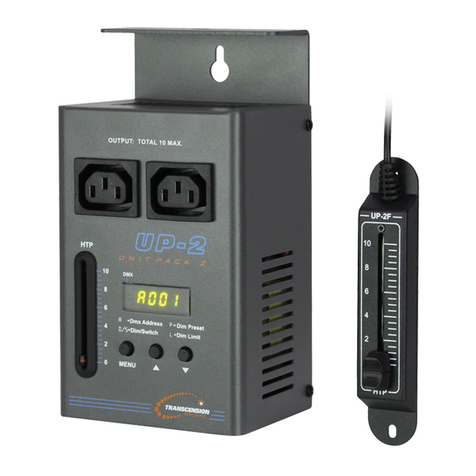
Transcension UP2-RF user manual

West Penn Wire
West Penn Wire AV-IP-NC811 Operation manual

IMC
IMC EAGLE 2 SOLR-2ELC-10 Service and parts manual supplement

Emerson
Emerson Hytork XL26 Installation, operation & maintenance instructions
