Micha Solar MSRx Mounting instructions
Micha Solar MSRx Charge Controller User Operation Manual
Page 1 of 46 Document: 802440-30.doc Date: December 2020 www.micha.co.uk
1. Overview
MSRx Charge Controller uses a microprocessor running embedded software to achieve the
required operation. Specific hardware has been designed to fulfil different input and output
requirements of an industrial charge controller while maintaining a cost effective solution. The
MSRx Software is the same for various specific solutions.
Quick Start Guide: Make it work quickly! Section 2 Page 2
Simple steps to get the controller powered up and working
General Operation: How does the Controller work? Section 3 Page 3
Explanation of the operation and functions available
Information Screens: What information is available? Section 4 Page 6
Information available to the user on the LCD Display
Changing Settings: How are settings changed? Section 5 Page 18
How to access and change the settings
Expansion Modules: What additional features are there? Section 6 Page 32
Description of features and functions that can be added
Battery Settings: What are the default settings? Section 7 Page 42
Tables of default Battery Settings programmed in the factory
Software History: What changed from the last version? Section 8 Page 45
Why and how the software has evolved over time
Micha Solar MSRx Charge Controller User Operation Manual
Page 2 of 46 Document: 802440-30.doc Date: December 2020 www.micha.co.uk
2. Quick Start Guide
2.1. System Concept
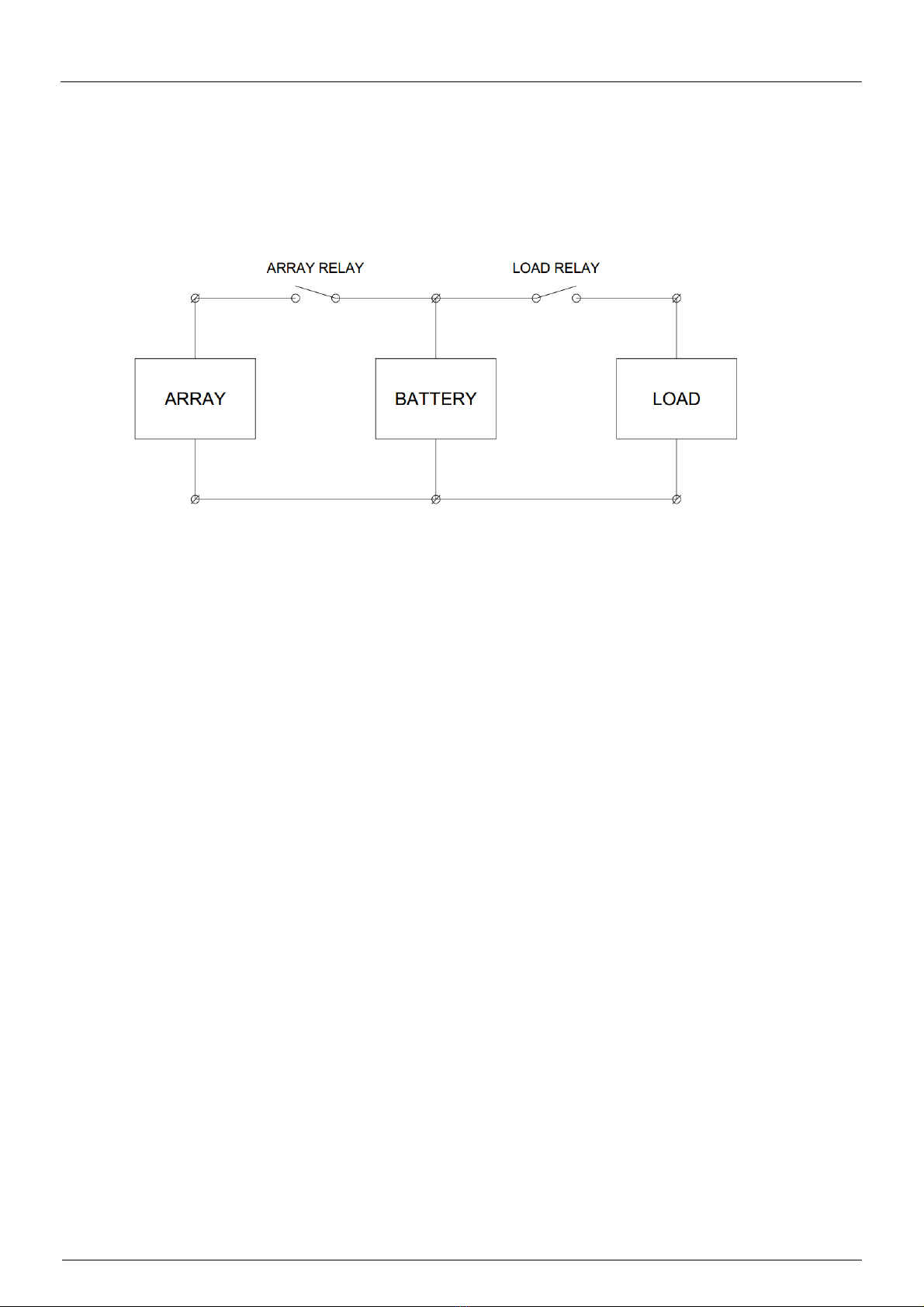
The following diagram shows a simple connection drawing of a Solar Power System:
The System shown has 1 x Array Input, 1 x Battery, and 1 x Load Output but the principle is the same if
the system has more than one Array Input and more than one Load Output.
The MSRx Charge Controller provides connections for the Array Input, Battery and Load Output.
It controls the Array & Load Relays to control the Battery charging and discharging.
2.2. System Connections:
2.2.1. Connect the Battery to the MSRx Battery Power connections
2.2.2. Connect the Battery to the MSRx Battery Voltage Sense connections
2.2.3. Connect the MSRx Temperature Sensor to the MSRx Battery Temperature Sense connections
2.2.4. Connect the PV Array(s) to the MSRx Array Input connections
2.2.5. Connect the Load to the MSRx Load Output connections
2.3. System Power On:
2.3.1. Turn on the Battery using whatever disconnect device is provided in the system
2.3.2. Ensure the Enable/Disable Link or Switch on the MSRx PSU/Load PCB Assembly (or MSRx
Interface PCB Assembly) is in the Enable position
2.3.3. Turn on each Array Input circuit breaker included in MSRx and externally (if fitted)
2.3.4. Turn on each Load Output circuit breaker included in MSRx and externally (if fitted)

Micha Solar MSRx Charge Controller User Operation Manual
Page 3 of 46 Document: 802440-30.doc Date: December 2020 www.micha.co.uk
3. MSRx General Operation
The MSRx Charge Controller is designed to control the charging of a battery in a solar power system,
preventing damage to the battery due to over-charging or under-charging. It provides maintenance and
supervisory functions and a convenient place to interconnect the solar arrays, battery bank and load
equipment. The controller is designed for industrial use in high ambient temperature applications.
3.1. MSRx Charge Controller Features
Measurement of Battery Voltage and Battery Temperature
Control of a number of Array Input Relays and Load Output Relays
Measurement of Array, Battery and Load Current
Battery Voltage Regulation Control Algorithm
4-20mA Outputs to signal other equipment
Volt-Free Alarm Relay Outputs & Volt-Free Digital Input to connect to other equipment
Communications Port to allow data communications to other equipment
3.2. Battery Voltage and Temperature Measurement
Battery Voltage and Temperature are measured if connected, and used to accurately control the
regulation of the battery as required by the battery manufacturer in order to maximise the battery life. To
maximise battery life the battery voltage and temperature should be measured at the battery terminals.
The Battery Temperature is used to calculate a Compensated Battery Voltage to control regulation.
An MSRx Temperature Sensor is provided with the controller. Alternatively, a Resistance Temperature
Detector (RTD) may be connected to a MSRx RTD Interface Module to measure temperature in
hazardous areas.
If the Battery Temperature Sensor has been selected, the MSRx will check for a valid temperature
between -25°C and +75°C. Outside of this range a Battery Temperature Alarm will be active.
3.3. Battery Voltage Regulation Modes
Boost Mode: (Battery Needs Charging)
Array Inputs will be connected to the Battery. If the total Array current is greater than the Load current,
the Battery will charge and the Battery Voltage will increase. When the Compensated Battery Voltage
reaches the Boost Regulation Voltage, the unit will enter the Equalisation Mode.
Equalisation Mode: (Battery Healthy)
Array Inputs will be disconnected and reconnected to the battery to regulate the Compensated Battery
Voltage at the Boost Regulation Voltage during the Equalisation Period. This ensures the battery
reaches its optimum state of charge. After the Equalisation Period, the unit will enter the Float Mode. If
the Test Mode has been enabled then the Equalisation period will be 60 seconds.
Float Mode: (Battery Healthy)
Array Inputs will be disconnected and reconnected to the battery to regulate the Compensated Battery
Voltage at the Float Regulation Voltage. If the Compensated Battery Voltage decreases below the
Reset-to Boost Voltage, the unit will reset to Boost Mode. This would typically happen overnight.
Night Mode:
If no Array Inputs are Ready-to-Charge, this is shown on Menu 0 as Night Mode. This is typically at night
and the charge controller will disconnect the Arrays Inputs from the battery to avoid the battery
discharging back through the array.

Micha Solar MSRx Charge Controller User Operation Manual
Page 4 of 46 Document: 802440-30.doc Date: December 2020 www.micha.co.uk
3.4. Battery Voltage Regulation Algorithm
In Software 801313 Version 5.0 and above the following Battery Voltage Regulation Algorithm is used:
The Battery Voltage is read every 0.1 seconds (the instant value). If the Compensated Instant Battery
Voltage is greater than or equal to the Battery Regulation Voltage, then all the Array Relays will be
disconnected and charging will stop immediately.
The Battery Voltage last 8 values are averaged, which is used for the Battery Voltage display. If the
Compensated Average Battery Voltage is less than the Battery Regulation Voltage minus the Regulation
Hysteresis Voltage (0.3V) then an Array Relay will be requested to be connected.
An Array Relay may only be connected if the open-circuit voltage of the PV Array is more than 2V above
the Battery Voltage.
The Array Connection Delay is 60 seconds.
After power up, there will be a delay of 60 seconds before the first Array is connected.
After any Array disconnection, there will be a delay of 60 seconds before any Array is connected.
After one Array is connected, there will be a delay of 60 seconds before the next Array is connected.
The Arrays will be used in such a way to distribute the operation among the Array Relays:
MSRx2 (2-stage Controller) => Array Relays are used in rotation: 1, 2
MSRx4 (4-stage Controller) => Array Relays are used in rotation: 1, 3, 2, 4
MSRx6 (6-stage Controller) => Array Relays are used in rotation: 1, 5, 3, 2, 6, 4
MSRx8 (8-stage Controller) => Array Relays are used in rotation: 1, 5, 3, 7, 2, 6, 4, 8
3.5. Array Voltage Measurement
The open-circuit Array Voltage is measured by disconnecting the Array from the Battery. If an Array
Input is connected to the Battery then the Array Relay is opened after a time interval to measure the
voltage.
3.6. System Normal / Common Alarm
System Normal is active if no Alarms are active.
Common Alarm is active if any Alarm is active.
3.7. High Voltage 1 & 2 Alarms
If the Compensated Battery Voltage is greater than or equal to the High Volts Set Voltage for the High
Volts Alarm Delay time, then the High Volts Alarm will be activated. If the Compensated Battery Voltage
is less than or equal to the High Volts Reset Voltage then the High Volts Alarm will be de-activated.
2 x High Volts Alarm functions are provided: HV1 and HV2 (HV2 is disabled by default).
When High Volts 1 Alarm is active, all the Array Relays will be disconnected.
3.8. Low Voltage 1 & 2 Alarms
If the Battery Voltage is less than or equal to the Low Volts Set Voltage for the Low Volts Alarm Delay
time, then the Low Volts Alarm will be activated. If the Battery Voltage is greater than or equal to the
Low Volts Reset Voltage then the Low Volts Alarm will be de-activated.
2 x Low Volts Alarm functions are provided: LV1 and LV2 (LV2 is disabled by default).

Micha Solar MSRx Charge Controller User Operation Manual
Page 5 of 46 Document: 802440-30.doc Date: December 2020 www.micha.co.uk
3.9. Load Cut 1 & 2 Alarms
If the Battery Voltage is less than or equal to the Load Cut Set Voltage for the Load Cut Alarm Delay
time, then the Load Cut Alarm will be activated. After the Load Cut Delay time, then the Load Relay will
be disconnected.
2 x Load Cut Alarm functions are provided: LC1 and LC2 (one for each Load Output).
3.10. Disabled Mode
If the Enable/Disable jumper link on the MSRx PSU/Load PCB Assembly (or the Enable/Disable switch
on the MSRx MDR Interface PCB Assembly) is set to the Disable position, then the Controller is in the
Disabled Mode. Depending on the setting of Menu D Screen 10 (see Section 5.5) the Array Relays
and/or Load Relays may be disconnected.
3.11. Battery Temperature Alarm
The Battery Temperature Alarm allows the user to create a Battery Temperature Alarm if the Battery
Temperature goes above or below user defined set-points (see Section 5.4 for details)
3.12. Low Charge Alarm
The Low Charge Alarm is designed to indicate when the Solar Power System is in a low state of charge.
See Section 5.3.
3.13. Array Failure Alarm
The Array Failure Alarm is designed to monitor each connected Array Input. This could be used to detect
if the Arrays are not providing charge or are stolen. See Section 5.3.
3.14. Initial Charge Mode
The Initial Charge Mode is designed to be used once at commissioning to ensure the batteries are in their
optimum condition. See Section 5.5.
3.15. Battery Temperature Charging Function
The Battery Temperature Charging Function is provided to disable battery charging above a user set
temperature and enable battery charging below a user set temperature. See Section 5.6.
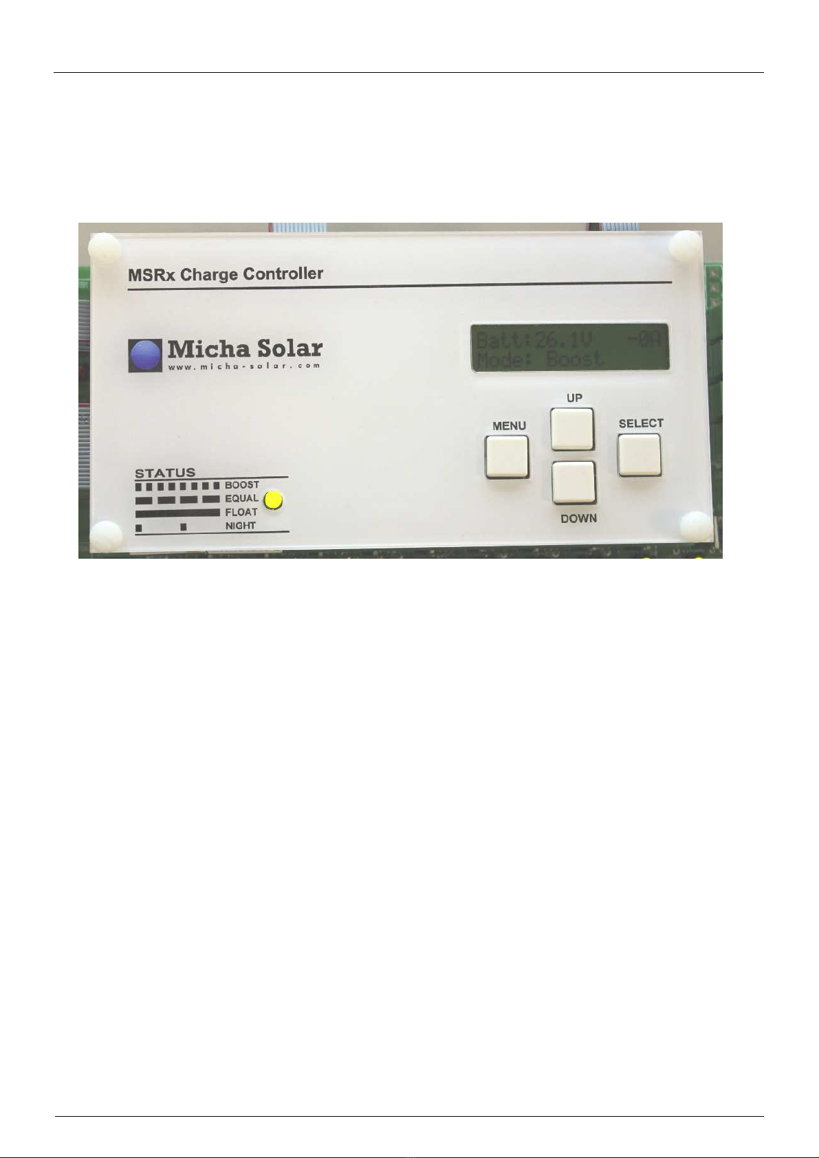
3.16. Status LED
A green Status LED is mounted on the MSRx Control PCB Assembly and is used to indicate the present
Mode of the Controller as described in the following table:
Mode Status LED Operation
Boost Mode Flash : 0.35 sec on - 0.35 sec off
Equalisation Mode Flash : 1.05 sec on – 0.35 sec off
Float Mode Steady
Night Mode Flash: 0.35 sec on – 2.45 sec off
Disabled Off

Micha Solar MSRx Charge Controller User Operation Manual
Page 6 of 46 Document: 802440-30.doc Date: December 2020 www.micha.co.uk
4. MSRx Information Screens
The MSRx Charge Controller has a 2-line by 16-character alphanumeric LCD Display which is used to display
system information and settings to the user.
MSRx Information Screens available to the user are shown on the following Menu Map:
4.1. Menu Navigation
Menu keypad switch moves the user along the Menus 0 to 6 and back to Menu 0.
Up and Down keypad switches moves the user up and down within a Menu.
Select keypad switch activates functions or selects a parameter to change its value.
Pressing Menu and Down switches at the same time will move the user to Menu 0 Screen 0.
Menu 0 Screen 0 is also called the Home Screen.
4.1.1. External Switch Input
Menu, Up, Down and Select switches may be duplicated on the exterior of the Controller (using suitable
IP rated switches) to allow the user to view the MSRx Information Screens. Alternatively, a single
External Switch may be connected to the MSRx Control PCB Assembly on the IN1 switch input and this
will provide a limited menu of screens to view some of the controller parameters.
See section 4.9

Micha Solar MSRx Charge Controller User Operation Manual
Page 7 of 46 Document: 802440-30.doc Date: December 2020 www.micha.co.uk
4.2. Menu 0 – System Information
Menu 0 Screen System Information Description
Batt:26.5V +123A
Batt SOC: 100%
1-Up Press Up switch to see the Battery State of Charge (0-100%)
Batt:26.5V +123A
Mode: Boost
Home
Screen
Battery Voltage and Current
Press Menu and Down Switches together to return to this screen
Batt:26.5V +123A
Arrays: 00000000
1-Down Press Down switch to see the Array Relay Status
(0 = Disconnected / 1 = Connected)
Menu 0 Notes:
Battery Current is shown as positive (+) for charge current
Battery Current is shown as negative (-) for discharge current
For a Dual Battery System, Screen 1-Up will show the Battery State of Charge for each Battery Input
Array Relays are also described as Array Switches in this manual.
Menu 0 Screen 0 (Home Screen):
The Home Screen will normally show the present Mode of the unit. If any Alarms are active, the display
will show each of the active alarms in sequence. The present Mode will be displayed for 2 seconds
followed by the list of alarms for 1 second each. See 4.2.1 for Mode & Alarm Descriptions.
Pressing the Up switch while in Menu 0 will show the Battery State of Charge % (Screen 1U).
Pressing the Down switch while in Menu 0 will show the Array Relay Status (Screen 1D). This screen
indicates whether the Array Input is connected or disconnected from the Battery. Reading left to right the
display indicates Arrays: 12345678 (depending on the number of Array Inputs).

Micha Solar MSRx Charge Controller User Operation Manual
Page 8 of 46 Document: 802440-30.doc Date: December 2020 www.micha.co.uk
4.2.1. Menu 0 Line 2 Mode & Alarm Descriptions
Menu 0 Line 2 Mode & Alarm Descriptions
Mode: Boost Boost Mode
Mode: Equal Equalisation Mode
Mode: Float Float Mode
Mode: Night Night Mode
Mode: Disabled Disabled Mode
Mode: Test Test Mode
Initial Charge Initial Charge Mode
Hi Volts 1 Alarm High Voltage 1 Alarm active
Lo Volts 1 Alarm Low Voltage 1 Alarm active
Load Cut 1 Alarm Load Cut 1 Alarm active (Load 1 Disconnected after delay)
Load Cut 2 Alarm Load Cut 2 Alarm active (Load 2 Disconnected after delay)
Hi Volts 2 Alarm High Volts 2 Alarm active
Lo Volts 2 Alarm Low Volts 2 Alarm active
Batt Volts Alarm Battery Voltage Sense Alarm
Batt Temp Alarm Battery Temperature Sense Alarm
Aux Temp Alarm Auxiliary Temperature Sense Alarm
Batt Hi Temp Alm Battery High Temperature Alarm active
Batt Lo Temp Alm Battery Low Temperature Alarm active
Low Charge Alarm Low Charge Alarm
Array1 Fail Alarm Array 1 Failure Alarm
Array2 Fail Alarm Array 2 Failure Alarm
Array3 Fail Alarm Array 3 Failure Alarm
Array4 Fail Alarm Array 4 Failure Alarm
Array5 Fail Alarm Array 5 Failure Alarm
Array6 Fail Alarm Array 6 Failure Alarm
Array7 Fail Alarm Array 7 Failure Alarm
Array8 Fail Alarm Array 8 Failure Alarm
O/p Feed Sum Alm Digital Input: Output Feeder Summary Alarm
Fire Detect Alrm Digital Input: Fire Detect Alarm
DCDC Fault Alarm Digital Input: DCDC Fault Alarm
OVL Fault Alarm Digital Input: OVL Fault Alarm
Batt1 Disconnect Digital Input: Battery 1 Disconnect Alarm
Batt2 Disconnect Digital Input: Battery 2 Disconnect Alarm
Earth Leak Alarm Digital Input: Earth Leak Alarm
Load MCCB Trip Digital Input: Load MCCB Trip
Load Volts Relay Digital Input: Load Volts Relay
Grnd Fault Alarm Digital Input: Ground Fault Alarm
Hi Load V1 Alarm High Load Voltage 1 Alarm
Lo Load V1 Alarm Low Load Voltage 1 Alarm
Hi Load V2 Alarm High Load Voltage 2 Alarm
Lo Load V2 Alarm High Load Voltage 2 Alarm

Micha Solar MSRx Charge Controller User Operation Manual
Page 9 of 46 Document: 802440-30.doc Date: December 2020 www.micha.co.uk
4.3. Menu 1 – System Information
Menu 1 Screen
System Information Description
System Info:
24V Neg Earth
0 System Voltage: 12V / 24V / 48V
System Polarity: Positive Earth or Negative Earth
Sys Volts: 25.6V
Sys Temp: +23.4C
1 Shows System Voltage and Temperature
See Notes
System Info:
Aux Volts: 24.5V
2 Auxiliary Voltage from Analog Input Module if fitted and enabled
See Notes
System Info:
Aux Temp: +23.4C
3 Aux Temperature from Analog Input Module if fitted and enabled
See Notes
System Info:
Solar: 1000W/m2
4 Solar Irradiation from Analog Input Module if fitted and enabled
See Notes
System Info:
Load V: 25.6V
5 Load Voltages
See Notes
System Info:
Array I: +123A
6 Total Array Current in Amps
(If the Array Shunt used is 60-150A then one decimal point is shown)
System Info:
Load I: +12A
7 Total Load Current in Amps
(If the Load Shunt used is 60-150A then one decimal point is shown)
System Info:
Batt I: +123A
8 Total Battery Current in Amps
(Calculated from Array Current – Load Current)
System Info:
Array AHr:123456
9 Array Current Amp-hours
System Info:
Load AHr: 123456
10 Load Current Amp-hours
System Info:
E/Time Hr:123456
11 Elapsed Time since last Amp-hour Reset
System Info:
Reset AHr -> SEL
12 Press Select to Reset Array Amp-hours, Load Amp-hours, and
Elapsed Time Hours
System Info:
Reset Alms-> SEL
13 Reset Alarms
Press Select to Reset any active alarm
System Info:
Total Hr: 123456
14 Total Run Time Hours
The Run Time cannot be reset
System Info:
Prog 801313 V4.5
15 Program Software Number (801313) and Version Number (4.5)
Menu 1 Notes: see next page

Micha Solar MSRx Charge Controller User Operation Manual
Page 10 of 46 Document: 802440-30.doc Date: December 2020 www.micha.co.uk
Menu 1 Notes:
If a DRM Analogue Input Module is fitted to the MSRx Controller, it can be enabled to measure and
display 1 x Auxiliary Voltage, 1 x Auxiliary Temperature and 1 x Solar Pyranometer. These inputs can
be used to measure a second Battery Voltage and Temperature if selected.
Menu 1 Screen 1 – System Voltage and System Temperature (Temp):
Single Battery System: Battery Voltage 1 (BV1) and Battery Temperature 1 (BT1)
BV1 connection is the Battery Voltage Sense Input on the MSRx PSU/Load PCB Assembly
BT1 connection is the Battery Temperature Sensor Input on the MSRx PSU/Load PCB Assembly
Dual Battery System: Battery Voltage 1 & 2 (BV1, BV2) and Battery Temperature 1 & 2 (BT1, BT2)
BV1 connection is the Battery Voltage Sense Input on the MSRx PSU/Load PCB Assembly
BT1 connection is the Battery Temperature Sensor Input on the MSRx PSU/Load PCB Assembly
BV2 connection is the Auxiliary Voltage Input on an Analog Input Module
BT2 connection is the Auxiliary Temperature Sensor on an Analog Input Module
System Voltage may be BV1 or the Average, Highest or Lowest of BV1 and BV2 (see Menu L)
System Temperature may be BT1 or the Average, Highest or Lowest of BT1 and BT2 (see Menu L)
A faulty or disconnected Temperature Sensor will show “---.-C”
Menu 1 Screen 2 – Auxiliary Voltage:
Menu 1 Screen 2 will change depending on functions selected in Setting Menu L:
System Info:
Aux Volts: (N/A)
Screen
2
Menu L Screen 0: Analog Input Module 1 = Disable
System Info:
Aux Volts: 26.3V
Screen
2
Menu L Screen 0: Analog Input Module 1 = Enable
Menu L Screen 1: Voltage Input = Enable
Menu L Screen 4: Voltage Input = Aux Volts
BV1 Volts: 26.4V
BV2 Volts: 26.5V
Screen
2
Menu L Screen 0: Analog Input Module 1 = Enable
Menu L Screen 1: Voltage Input = Enable
Menu L Screen 4: Voltage Input = BV1/BV2 Av, Hi, Lo
Menu 1 Screen 3 – Auxiliary Temperature:
Menu 1 Screen 3 will change depending on functions selected in Setting Menu L:
System Info:
Aux Temp: (N/A)
Screen
3
Menu L Screen 0: Analog Input Module 1 = Disable
System Info:
Aux Temp: +23.4C
Screen
3
Menu L Screen 0: Analog Input Module 1 = Enable
Menu L Screen 2: Temperature Input = Enable
Menu L Screen 4: Temperature Input = Aux Temp
BT1 Temp: +23.5C
BT2 Temp: +23.6C
Screen
3
Menu L Screen 0: Analog Input Module 1 = Enable
Menu L Screen 2: Temperature Input = Enable
Menu L Screen 4: Temperature Input = BT1/BT2 Av, Hi, Lo
Menu 1 Screen 4 – Solar Irradiation:
Menu 1 Screen 4 will change depending on functions selected in Setting Menu L:
Micha Solar MSRx Charge Controller User Operation Manual
Page 11 of 46 Document: 802440-30.doc Date: December 2020 www.micha.co.uk
System Info:
Solar: (N/A)
Screen
4
Menu L Screen 0: Analog Input Module 1 = Disable
System Info:
Solar: 1000W/m2
Screen
4
Menu L Screen 0: Analog Input Module 1 = Enable
Menu L Screen 3: Solar Input = Enable
Menu 1 Screen 5 – Load Voltages:
If the MSRx is set as a 19” Rack Controller, the following screen will be shown:
System Info:
Load V: 26.5V
Screen
5
Load Voltage is measured at the MSRx Battery Connections
If the MSRx is set as a Version 1 or Version 2 Controller, one of the following screens will be shown:
System Info:
Load V: (N/A)
Screen
3
Menu B Screen 3: Load Voltage: None
System Info:
Load 1 V: 26.5V
Screen
3
Menu B Screen 3: Load Voltage: Load 1
System Info:
Load 2 V: 26.5V
Screen
3
Menu B Screen 3: Load Voltage: Load 2
Load 1 V: 26.4V
Load 2 V: 26.5V
Screen
3
Menu B Screen 3: Load Voltage: Load 1 & 2
Micha Solar MSRx Charge Controller User Operation Manual
Page 12 of 46 Document: 802440-30.doc Date: December 2020 www.micha.co.uk
4.4. Menu 2 – System Settings
Menu 2 Screen System Settings Description
System Settings:
Boost V: 28.8V
0 Boost Regulation Voltage
System Settings:
Float V: 28.2V
1 Float Regulation Voltage
System Settings:
Rst to Bst:26.4V
2 Reset to Boost Voltage
System Settings:
HV1 Set V: 29.4V
3 High Volts 1 Alarm Set (Activation) Voltage
System Settings:
HV1 Rst V: 28.8V
4 High Volts 1 Alarm Reset Voltage
System Settings:
LV1 Set V: 22.8V
5 Low Volts 1 Alarm Set (Activation) Voltage
System Settings:
LV1 Rst V: 24.0V
6 Low Volts 1 Alarm Reset Voltage
System Settings:
LC1 Set V: 22.2V
7 Load Cut 1 Alarm Set (Activation) Voltage
System Settings:
LC1 Rst V: 24.0V
8 Load Cut 1 Alarm Reset Voltage
System Settings:
LC2 Set V: 21.6V
9 Load Cut 2 Alarm Set (Activation) Voltage
System Settings:
LC2 Rst V: 24.0V
10 Load Cut 2 Alarm Reset Voltage
System Settings:
LC1 Delay: 10sec
11 Load Cut 1 Delay Period in seconds
Time between Load Cut 1 Alarm activation and Load 1 disconnection
System Settings:
LC2 Delay: 10sec
12 Load Cut 2 Delay Period in seconds
Time between Load Cut 2 Alarm activation and Load 2 disconnection
System Settings:
Equalisation:30m
13 Equalisation Period in minutes
System Settings:
MSRx: Version 2
14 MSRx Control PCB Assembly Hardware:
Select Version 1, Version 2, or 19” Rack
System Settings:
No of Arrays: 4
15 Number of Array Inputs: 1-8
e.g. 3 = MSRx3, 8 = MSRx8

Micha Solar MSRx Charge Controller User Operation Manual
Page 13 of 46 Document: 802440-30.doc Date: December 2020 www.micha.co.uk
4.5. Menu 3 – Test Relays and Loads
Menu 3 Screen
Test Relays & Loads Description
Test Relay 1:
Press --> Select
0 Test Relay 1
Press Select to change the state of the Relay contacts and LED
Test Relay 2:
Press --> Select
1 Test Relay 2
Press Select to change the state of the Relay contacts and LED
Test Relay 3:
Press --> Select
2 Test Relay 3
Press Select to change the state of the Relay contacts and LED
Test Relay 4:
Press --> Select
3 Test Relay 4
Press Select to change the state of the Relay contacts and LED
Test Load 1 Rly:
Press --> Select
4 Test Load 1 Relay
Press Select to change the state of Load 1 Relay and LED
Test Load 2 Rly:
Press --> Select
5 Test Load 2 Relay
Press Select to change the state of Load 1 Relay and LED
Test Mode: Off
Press --> Select
6 Test Mode: Off or On
Press Select to change the state of the Test Mode
Test RMx Relay 1
Press --> Select
7 Test Relay Module x Relay 1
Press Select to change the state of the Relay contacts and LED
Test RMx Relay 2
Press --> Select
8 Test Relay Module x Relay 2
Press Select to change the state of the Relay contacts and LED
Test RMx Relay 3
Press --> Select
9 Test Relay Module x Relay 3
Press Select to change the state of the Relay contacts and LED
Test RMx Relay 4
Press --> Select
10 Test Relay Module x Relay 4
Press Select to change the state of the Relay contacts and LED
Test Relay 5:
Press --> Select
11 Test Relay 5 (This screen is only visible for MSRx 19” Version)
Press Select to change the state of the Relay contacts and LED
Test Relay 6:
Press --> Select
12 Test Relay 6 (This screen is only visible for MSRx 19” Version)
Press Select to change the state of the Relay contacts and LED
Menu 3 Notes:
Pressing Select will toggle the state of the Relay for as long as Select is pressed
Screens 7-10 will test one Relay on all connected Relay Modules at the same time:
e.g. Module 1 Relay 1 AND Module 2 Relay 1 etc
(this is just for test purposes to check the operation and wiring of the relay contacts)

Micha Solar MSRx Charge Controller User Operation Manual
Page 14 of 46 Document: 802440-30.doc Date: December 2020 www.micha.co.uk
4.6. Menu 4 – Test Array Switches
Caution:
Testing the Array Solid-State Switches, (Relays or Contactors depending on Controller design)
will connect or disconnect the Array Inputs to or from the Battery.
Menu 4 Screen Test Array Switches/Relays Description
Test Array 1 Sw:
Press + hold SEL
0 Test Array 1 Solid-State Switch / Relay / Contactor
Test Array 2 Sw:
Press + hold SEL
1 Test Array 2 Solid-State Switch / Relay / Contactor
Test Array 3 Sw:
Press + hold SEL
2 Test Array 3 Solid-State Switch / Relay / Contactor
Test Array 4 Sw:
Press + hold SEL
3 Test Array 4 Solid-State Switch / Relay / Contactor
Test Array 5 Sw:
Press + hold SEL
4 Test Array 5 Solid-State Switch / Relay / Contactor
Test Array 6 Sw:
Press + hold SEL
5 Test Array 6 Solid-State Switch / Relay / Contactor
Test Array 7 Sw:
Press + hold SEL
6 Test Array 7 Solid-State Switch / Relay / Contactor
Test Array 8 Sw:
Press + hold SEL
7 Test Array 8 Solid-State Switch / Relay / Contactor
Menu 4 Notes:
Pressing Select will toggle the state of the Array Relay for as long as Select is pressed.
The number of screens visible in this Menu depends on the Number of Array Inputs for the Controller
(see Menu 2 Screen 15) e.g. MSRx4 will only show Screens 0-3.

Micha Solar MSRx Charge Controller User Operation Manual
Page 15 of 46 Document: 802440-30.doc Date: December 2020 www.micha.co.uk
4.7. Menu 5 – Array Voltages
Caution:
Showing an Array Input Voltage will disconnect the Array Input from the Battery
Menu 5 Screen Show Array Voltages Description
Show Array 1 V:
Press + hold SEL
0 Show Array 1 open-circuit Array Voltage
Show Array 2 V:
Press + hold SEL
1 Show Array 2 open-circuit array voltage
Show Array 3 V:
Press + hold SEL
2 Show Array 3 open-circuit array voltage
Show Array 4 V:
Press + hold SEL
3 Show Array 4 open-circuit array voltage
Show Array 5 V:
Press + hold SEL
4 Show Array 5 open-circuit array voltage
Show Array 6 V:
Press + hold SEL
5 Show Array 6 open-circuit array voltage
Show Array 7 V:
Press + hold SEL
6 Show Array 7 open-circuit array voltage
Show Array 8 V:
Press + hold SEL
7 Show Array 8 open-circuit array voltage
Menu 5 Notes:
Pressing Select will open (or keep open) the Array Relay for as long as Select is pressed
The number of screens visible in this Menu depends on the Number of Array Inputs for the Controller
(see Menu 2 Screen 15) e.g. MSRx4 will only show Screens 0-3.
It is only possible to measure the open circuit Array Voltage if there is a PV Array Module connected to
the Array Input, and if any Array Input Circuit Breaker is in the ON position.
Micha Solar MSRx Charge Controller User Operation Manual
Page 16 of 46 Document: 802440-30.doc Date: December 2020 www.micha.co.uk
4.8. Menu 6 – Array Currents
Caution:
Showing an Array Input Current will connect that Array Input to the Battery and disconnect all
other Array Inputs from the Battery
Menu 6 Screen Show Array Currents Description
Show Array 1 I:
Press --> Select
0 Show Array 1 Current
Show Array 2 I:
Press --> Select
1 Show Array 2 Current
Show Array 3 I:
Press --> Select
2 Show Array 3 current
Show Array 4 I:
Press --> Select
3 Show Array 4 current
Show Array 5 I:
Press --> Select
4 Show Array 5 current
Show Array 6 I:
Press --> Select
5 Show Array 6 current
Show Array 7 I:
Press --> Select
6 Show Array 7 current
Show Array 8 I:
Press --> Select
7 Show Array 8 current
Menu 6 Notes:
Pressing Select will connect that Array Input to the Battery and disconnect all other Array Inputs from the
Battery for 5 seconds and show the Array Current on the display. The user will be unable to move up
and down the Menu during the 5 second period.
The number of screens visible in this Menu depends on the Number of Array Inputs for the Controller
(see Menu 2 Screen 15) e.g. MSRx4 will only show Screens 0-3.
It is only possible to measure the closed circuit Array Current if there is a PV Array Module connected to
the Array Input, and if any Array Input Circuit Breaker is in the ON position.

Micha Solar MSRx Charge Controller User Operation Manual
Page 17 of 46 Document: 802440-30.doc Date: December 2020 www.micha.co.uk
4.9. Menu X – External Switch Menu (Added in Software 801313 V6.0)
Menu X Screen
External Switch Menu
Batt:26.5V +123A
Mode: Boost
0 Battery Voltage and Current
Mode and active alarms
Load V: 26.0V
Load I: 23A
1 Load Voltage and Current
Array 1: 34.5V
15A
2 Array 1 Open-Circuit Voltage and Closed Circuit Current
Array 2: 34.5V
15A
3 Array 2 Open-Circuit Voltage and Closed Circuit Current
Array 3: 34.5V
15A
4 Array 3 Open-Circuit Voltage and Closed Circuit Current
Array 4: 34.5V
15A
5 Array 4 Open-Circuit Voltage and Closed Circuit Current
Array 5: 34.5V
15A
6 Array 5 Open-Circuit Voltage and Closed Circuit Current
Array 6: 34.5V
15A
7 Array 6 Open-Circuit Voltage and Closed Circuit Current
Array 7: 34.5V
15A
8 Array 7 Open-Circuit Voltage and Closed Circuit Current
Array 8: 34.5V
15A
9 Array 8 Open-Circuit Voltage and Closed Circuit Current
Menu X Notes:
Menu X is entered by pressing the switch connected to the MSRx Control PCBA IN1 input.
Menu X provides a limited number of screens with system information.
Pressing the External Switch will loop round the screens in turn.
After 4 minutes of no switch presses (External or Internal) the screen will return to the Home Screen.
This Menu allows the user to see a limited number of screens without opening the door (if there is a
window installed in the enclosure).
Micha Solar MSRx Charge Controller User Operation Manual
Page 18 of 46 Document: 802440-30.doc Date: December 2020 www.micha.co.uk
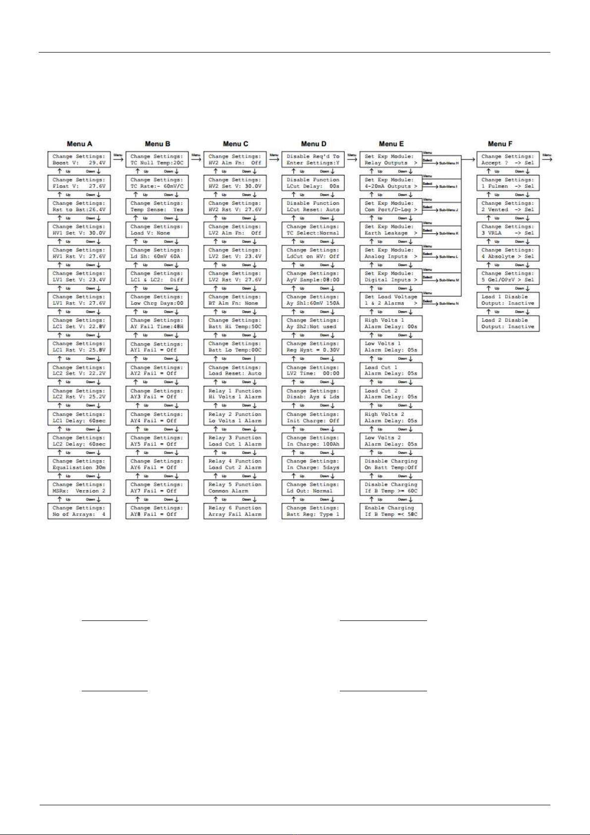
5. MSRx Change Settings Screens
MSRx Change Settings Screens allow a user to modify the parameters used in the controller.
The Screens available to the user are described on the following Menu Map:
5.1. Entering the Change Settings Menus
MSRx Standard Charge Controller:
On the MSRx PSU/Load PCB Assembly, insert the jumper link on LK1 in the Disable position (or on the
MSRx Interface PCB Assembly, move the Enable/Disable Switch to the Disable position).
Press and hold the Menu, Up and Down keypad switches all at the same time and then press Select.
MSRx 19” Rack Unit:
Ensure the front panel key-switch is turned to “Keypad Enable”.
Press and hold the Menu, Up and Down keypad switches all at the same time and then press Select.

Micha Solar MSRx Charge Controller User Operation Manual
Page 19 of 46 Document: 802440-30.doc Date: December 2020 www.micha.co.uk
5.1.1. Menu Navigation
The Menu, Up and Down switches are used to navigate to the setting to be changed.
Pressing the Select switch will make the parameter flash. The Up and Down switches are then
used to vary the value. The Select switch is pressed again and the value will stop flashing.
The Menu, Up and Down switches are used again to navigate to another setting to be changed or
to navigate to the “Accept” screen.
Auto-Repeat: When a setting value is flashing, if the Up or Down switch is pressed and held for
more than 0.5 seconds, then the parameter will increase or decrease rapidly.
5.1.2. Accepting Changes to Settings
IMPORTANT:
After adjusting any parameter, the user MUST navigate to the “Accept” screen and press the
Select switch.
The unit will not remember any changes to settings unless they are accepted using this screen.
5.1.3. Default Settings
The user can reset some of the battery settings back to factory default settings (presets).
Refer to Section 5.7 and Section 7 for the battery settings which are re-programmed if the user
chooses to reset some settings back to the factory default settings (presets).
5.1.4. Exiting the Change Settings Menus
Pressing the Menu switch at one of the Menu F screens, will exit the Change Settings Menus
without remembering any changes. The user is taken back to Menu 0.
Pressing the Select switch at the Accept screen (Screen 0) will exit the Change Settings Menus
and will remember any changes. The user is taken back to Menu 0.
Pressing the Select switch at any of the battery Settings Default screens will exit the Change
Settings Menus and the new default values will be programmed into the unit. The user is taken
back to Menu 0.
Micha Solar MSRx Charge Controller User Operation Manual
Page 20 of 46 Document: 802440-30.doc Date: December 2020 www.micha.co.uk
5.2. Menu A – Change Settings
Menu A Screen
Change Settings Description
Change Settings:
Boost V: 28.2V
0 Boost Regulation Voltage
Change Settings:
Float V: 27.4V
1 Float Regulation Voltage
Change Settings:
Rst to Bst:25.3V
2 Reset to Boost Voltage
Change Settings:
HV1 Set V: 28.8V
3 High Volts 1 Alarm Set (Activation) Voltage (see section
Change Settings:
HV1 Rst V: 25.8V
4 High Volts 1 Alarm Reset Voltage (see section
Change Settings:
LV1 Set V: 22.8V
5 Low Volts 1 Alarm Set (Activation) Voltage (see section
Change Settings:
LV1 Rst V: 27.0V
6 Low Volts 1 Alarm Reset Voltage (see section
Change Settings:
LC1 Set V: 22.2V
7 Load Cut 1 Alarm Set (Activation) Voltage (see section
Change Settings:
LC1 Rst V: 27.0V
8 Load Cut 1 Alarm Reset Voltage (see section
Change Settings:
LC2 Set V: 21.6V
9 Load Cut 2 Alarm Set (Activation) Voltage (see section
Change Settings:
LC2 Rst V: 24.6V
10 Load Cut 2 Alarm Reset Voltage (see section
Change Settings:
LC1 Delay: 10sec
11 Load Cut 1 Delay (5 to 240 seconds)
Time between LC1 Alarm activated and Load 1 disconnected
Change Settings:
LC2 Delay: 10sec
12 Load Cut 2 Delay (5 to 240 seconds)
Time between LC2 Alarm activated and Load 2 disconnected
Change Settings:
Equalisation 30m
13 Equalisation Period (1 to 90 minutes)
Change Settings:
MSRx: Version 2
14 MSRx Control PCB Assembly Hardware: (Default: Version 2)
Version 1 = 400327, Version 2 = 401764, 19” Rack = 400766
Change Settings:
No of Arrays: 4
15 Number of Array Inputs: 1-8
e.g. 8 = MSRx8 = 8 stage Charge Controller
Popular Inverter manuals by other brands


 quick guide")


Kraftixx
Kraftixx PPG 3500 Original operating instructions

Sunerg Solar Energy
Sunerg Solar Energy TENDAEVO 1T installation manual

TBB power
TBB power Raython Series user manual

Microcare
Microcare 600W-24V user manual

STORZ POWER
STORZ POWER SOL-ARK 12k installation manual

Gallagher
Gallagher S220 Wiring instructions