GR-UM-201-A-04GR-UM-201-A-0
PV+
PV-
12
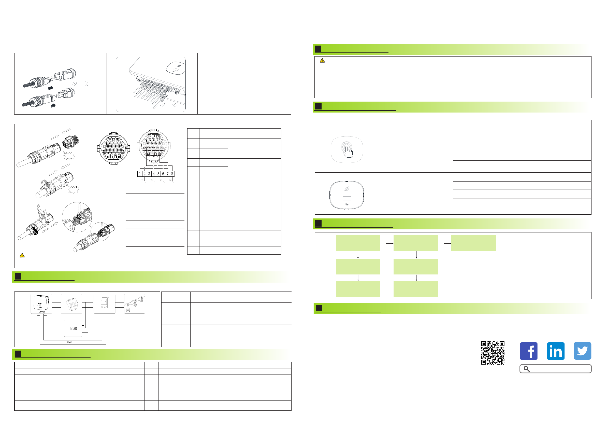
3.3.2 Plug in PV terminal
Note:
1.Before installing the PV terminal, please
double-check that the PV input voltage and
current do not exceed the MPPT limits.
2.When installing the PV terminal, pay
attention to the difference between the
positive and negative poles and the one-to-
one correspondence between the terminals
and the machine.
3.There is a "click" sound when the terminal
is connected,please gently pulling the PV
wire to make sure there is no loose or
pulling off.
3.3.3 Communication cable installation
Click
Click
Download
Manual Growatt New Energy
5.
Post-installation check
The inverter is installed correctly, firmly and reliably.
The RS485 communication cable is installed correctly and firmly.
The ground wire connected well and the connection is firm
and reliable.
The cable tie port is trimmed well without leaving sharp
corners,meets the requirements of the user.
All switches are in the OFF state.
All exposed terminals are well protected and there are no vacant
ports.
All wiring is correct and securely connected.
Pay attention to clean up all construction residues.
The wiring of the cable is reasonable, meets the
requirements, and there is no phenomenon of broken skin.
Connecting Meter
4.
The following table describes how we can connect EASTRON meter (TPM-E)to inverter:
Meter Pin NO. Description Meter Connection
1/2/3/4
5/6/7/8
A
B
L1/L2/L3/N-in
L1/L2/L3/
N-out
RS485A
RS485B
Grid L1/L2/L3/N
AC connector & Load L1/L2/L3/N
SYS COM Pin 7 RS485A2
SYS COM Pin 8 RS485B2
L1
L2
L3
N
L1
L2
L3
N
1
2
3
4
L1
L2
L3
N
5
6
7
8
B A
Customer can read more information by push button.
Switch the display interface or the
current number plus 1
Enter the setting state or confirm
Return to the previous display
interface
The current data returns to the
default value
Inverter status indicator
It can display the basic information of inverter through LCD display
screen (PV/AC voltage,PV power,AC current,total power,generating
capacity, etc.).
Shenzhen Growatt New Energy CO.,LTD
4-13/F,Building A,Sino-German(Europe) Industrial Park,
Hangcheng Ave,Guxing Community,Xixiang Subdistrict,
Bao’an District, Shenzhen, China
+86 0755 2747 1942
www.ginverter.com
T
E service@ginverter.com
W
7. Status of PV grid inverter
9.
Service and contact
Note:
6.
Power on and off steps
8.
Export limitation setting
Exporlimit
OFF ON
Password
123
Set parameter
General
Advanced
Meter
CT
ExportLimit Rate
XXX.X%
Set OK
If the local grid company requires to limit the
output power from your inverter systems,we
introduce the concept of Export Limit Rate.The
ratio of your system output power divided by
the rated power of the inverter is called Export
Limited Rate.For example,if the local grid
companyonly accepts 4kW from your 5kW
system,then the Export Limit Rate of 5kW
inverter should be 80%.
Inverter side
Click!
Click!
Dry junction : external
relay coil interface,
power is not more than
2W
BAT communication
port(reserved)
When connecting the communication line,port 15 and 16 are not connected,as for the other function,please refer to the above table
according to the customer needs.
Note:
connect
to RRCR
Before turning the inverter on, please make sure the PV input voltage and current are within the MPPT limits.
Follow the steps below to turn the inverter on:
1.Switch on the build-in DC isolator at the bottom of the inverter.
2.Switch on the PV Array and DC isolator next to your inverter, if you can not find this switch, skip this step.
3.Switch on the Solar AC isolator if the inverter is more than 3 meters away from your switchboard.
4.Switch on the solar supply main switch in the switch board.


