Microcare 600W-24V User manual
Pure Sine Wave Inverter
600W-24V
User Manual
Manual Version:INV-600W-2016-1

1
Table of Contents
1. INTRODUCTION...................................................................................................................1
1.1 General Description ........................................................................................................1
1.2 Key Features...................................................................................................................2
2. SAFETY INSTRUCTIONS ....................................................................................................2
2.1 Installation Location ........................................................................................................2
2.2 Precautions When Working With Batteries .....................................................................2
2.3 Battery Charging.............................................................................................................2
2.4 Battery Reverse Polarity Connection ..............................................................................2
3. INVERTER OVERVIEW........................................................................................................3
3.1 Inverter Front View..........................................................................................................3
3.2 Inverter Bottom View.......................................................................................................3
4. GENERAL WIRING INFORMATION.....................................................................................4
4.1 DC Wiring........................................................................................................................4
4.2 Battery Connection Methods...........................................................................................4
4.2.1 Parallel Battery Connection......................................................................................4
4.3 AC Wiring........................................................................................................................4
5. INVERTER OPERATION......................................................................................................5
5.1 Front Panel LED Display.................................................................................................5
5.2 Inverter Status LED’s ......................................................................................................5
5.2.1 Inverter Switched Off................................................................................................5
5.2.2 Inverter Switched ON................................................................................................5
5.2.3 Overload...................................................................................................................5
5.2.4 Battery Low/High ......................................................................................................6
5.2.5 Temp ........................................................................................................................6
5.3 Connecting the Load.......................................................................................................6
6. MAINTENANCE AND SERVICE...........................................................................................6
6.1 Fuse Replacement..........................................................................................................6
7. SPECIFICATIONS................................................................................................................7
8. DESTRIER ELECTRONICS LIMITED CARRY- IN WARRANTY..........................................8
9. REGISTRATION OF MY MICROCARE PRODUCT .............................................................9
1. INTRODUCTION
1.1 General Description
Microcare Inverters are Pure Sine Wave Inverters designed to obtain optimum inverted AC power
from an installed DC Solar System. Microcare Inverters use galvanic isolation resulting in the product
being highly robust and reliable with low standby current and high efficiency ratings. The unit is
supplied with attached battery cable & clamps and is ideal for running of small appliances.

2
1.2 Key Features
Pure Sine Wave with LED indicators High Efficiency Superior Overload Capability Full
Protection Fan Cooled 3 year Warranty
2. SAFETY INSTRUCTIONS
2.1 Installation Location
Install the Inverter indoor in a dry protected location away from any sources of moisture.
Find a suitable temperature resistant surface to mount the inverter.
The mounting surface must support the weight of the inverter.
Exposure to saltwater is particularly destructive.
Do not mount the inverter in a closed container.
Unrestricted airflow is required for the inverter to operate at optimal efficiency.
Ensure a 200mm unrestricted clearance at the top, left and right side of the inverter
Do not install the inverter in the same compartment as non-sealed batteries.
Locate the Inverter as close as possible to the batteries in order to keep the battery cables
as short as possible as supplied with the inverter.
2.2 Precautions When Working With Batteries
Ensure that the inverter is switched off and all loads disconnected before disconnecting the
battery leads.
Be cautious not to drop any tool or metal objects on the battery, this can cause a short circuit
or spark and could cause an explosion.
Flooded batteries contain sulphuric acid and care should be taken to prevent contact with
eyes, clothing and skin.
Do not smoke or allow a spark or flame near the batteries.
Remove metal items like rings, bracelets and watches when working with batteries, this could
cause a short circuit and cause a severe burn.
2.3 Battery Charging
Ensure that the max battery charge voltage from any charging device is lower than
16,5VDC.
2.4 Battery Reverse Polarity Connection
Incorrect battery polarity connection can cause severe damage to the inverter.
3
3. INVERTER OVERVIEW
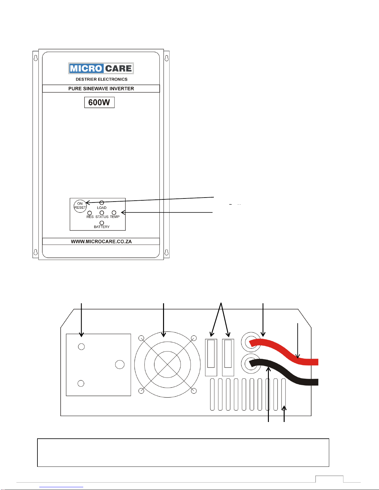
3.1 Inverter Front View
Figure 3-1
3.2 Inverter Bottom View
Figure 3-2
1. 230V AC Outlet 2. Cooling Fan 3. 2 x 30A Fuses
4. Battery Cable Positive 5. Battery Cable Negative
6. Ventilation Holes
1
2
4
3
6
5
LED Indicators
ON/OFF/Reset
Button
4
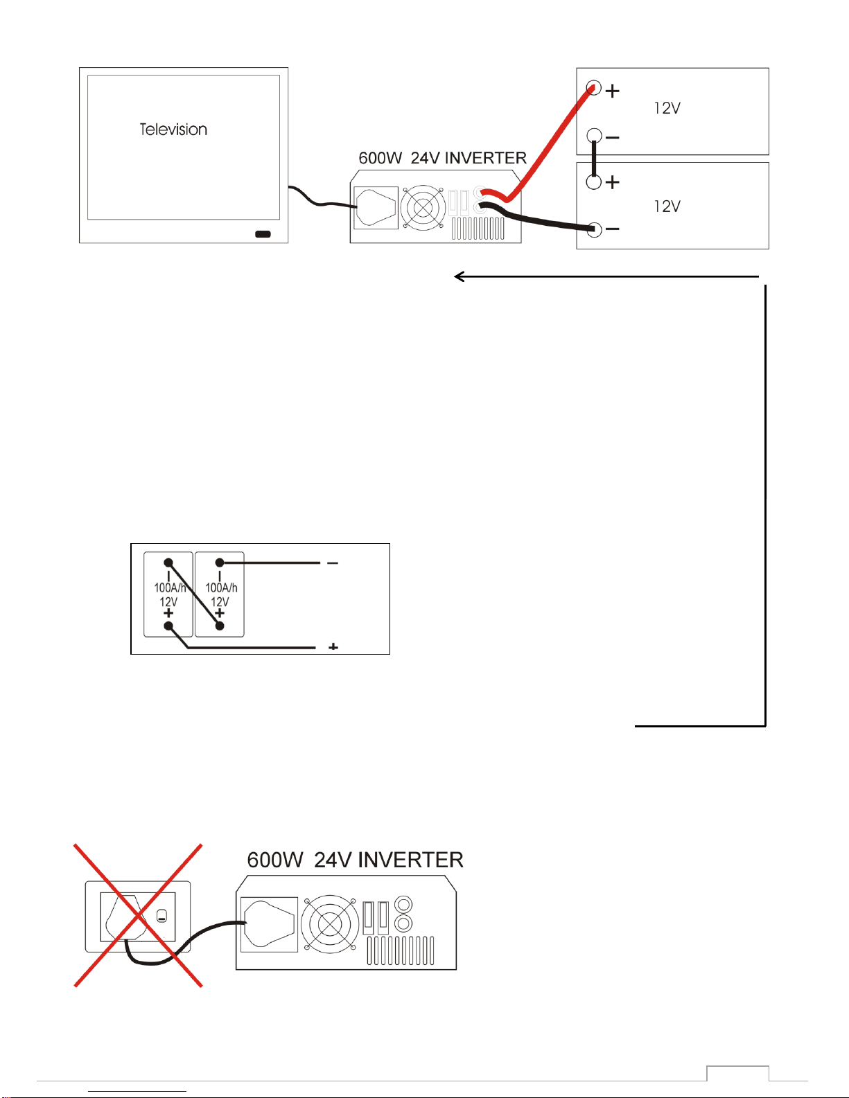
4. GENERAL WIRING INFORMATION
Fig 4.1
Familiarize yourself with the content of the manual following before commencing with the
wiring.
4.1 DC Wiring
Connect the Positive (Red) battery lead from the inverter to the positive post of the battery.
Connect the Negative (Black) battery lead from the inverter to the negative post of
the battery.
Ensure that the battery lead lugs are properly tightened.
The Status LED starts flashing.
4.2 Battery Connection Methods
4.2.1 Series Battery Connection
Current remains at 100AH 12V + 12v = 24V
Series Connection (Amperage stays the same as a single battery, voltage increases)
4.3 AC Wiring
Connect the appliance “AC Load” to the plug socket on the inverter as in Fig 4-1
Do not connect the AC output of the inverter directly to another AC source.
The AC output of this inverter cannot be connected in parallel with another AC source such as the
power from the Grid or a generator. Parallel connection will result in feeding back into the inverter
and will instantly damage the inverter..
5
5. INVERTER OPERATION
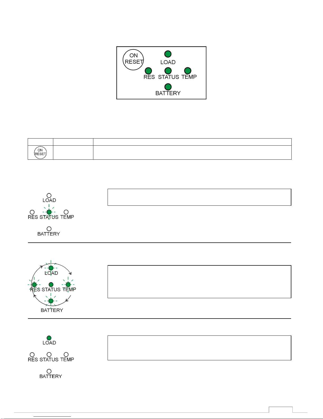
5.1 Front Panel LED Display
Figure 5-1: LED Display
The front Panel Display indicates the Inverter’s operational information.
Button Function Description
Symbol
Button Name
Function description
On/Reset
Switches the inverter ON or OFF, resets the inverter
5.2 Inverter Status LED’s
5.2.1 Inverter Switched Off
5.2.2 Inverter Switched ON
5.2.3 Overload
“STATUS LED” Blinking indicates that the inverter is switched off.
“STATUS LED” steady ON and the other LEDS rotating in a
clockwise direction indicates that the inverter is switched on a
producing 230VAC
“LOAD LED” Steady ON indicates that the inverter has switched
off due to an overload.
6
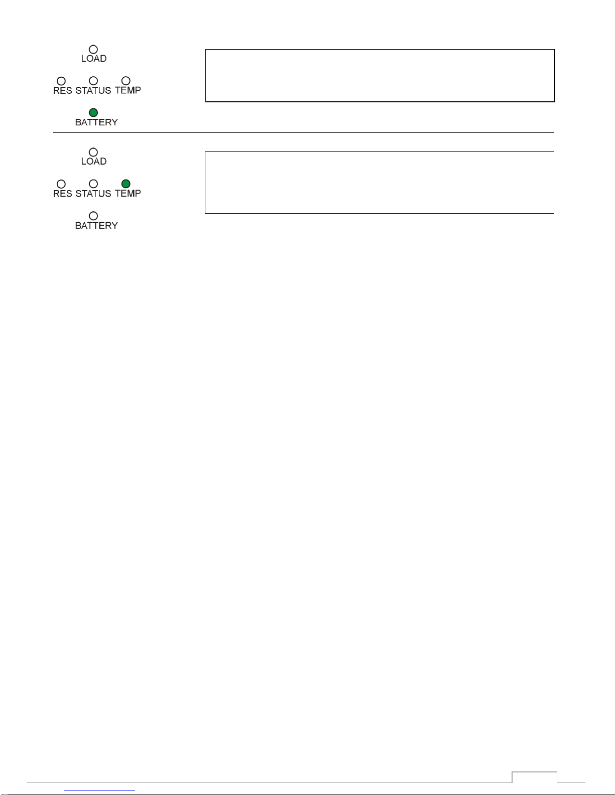
5.2.4 Battery Low/High
5.2.5 Temp
5.3 Connecting the Load
Ensure that the load does not exceed the rating of the inverter.
Ensure that the Inverter is switched off. Status LED flashes.
Plug the equipment into the AC outlet socket of the inverter.
Switch the inverter ON. “Push the On/Reset Button”
Switch the load ON.
6. MAINTENANCE AND SERVICE
6.1 Fuse Replacement
If the inverter does not switch on, there is a possibility of a blown fuse caused by DC reverse polarity,
short circuit or overload.
To check the fuses:
Disconnect all AC loads
Disconnect the Battery
Remove the Fuses as indicated in on diagram 3.2.
Visually inspect each of the 2 fuses.
Blown fuses will have a damaged filament.
Replacement fuses should be 30A rated quick-blow automotive type fuses only.
Reconnect wire connections per the installation instructions in Section 4.0
“BATTERY LED” Steady ON indicates that the inverter has
switched off due to low battery voltage < 10,5V or high battery
voltage >16V
“TEMP LED” Steady ON indicates that the inverter has switched
off due to high temperature >80 Degree Celsius

SPECIFICATIONS
7
7. SPECIFICATIONS
Model
600W 24V
Wattage
600W
Input DC Voltage
24V
Input Voltage Range
21 to 32VDC
Output AC Voltage
230VAC
Output Frequency
50Hz
Surge Rating
200%
Efficiency
<95%
Output Waveform
Sine Wave THD 93%
Protection
Fuse, Short Circuit, Reverse Polarity, Over
Temperature
Recommended Battery Size
2x 12V , Minimum 105Ah
Operating Temperature
Range
0-50 Deg C
Cooling
Fan Cooling
Dimensions
275 x 220 x 90mm
Weight
7,6 kg
Warranty
1yr

DESTRIER ELECTRONICS LIMITED CARRY- IN WARRANTY
8
8. DESTRIER ELECTRONICS LIMITED CARRY- IN WARRANTY
Destrier Electronics warrants this 600W Inverters against defects in workmanship and materials, fair
wear and tear accepted, for a period of 1 (One) year from the date of delivery/collection and is based
on a carry-in basis. Where the installation of the product makes it impractical to carry-in to our
workshops, Destrier Electronics reserves the right to charge for travel time and kilometres travelled to
and from the site where the product is installed.
During this warranty period, Destrier Electronics will, at its own discretion, repair or replace the
defective product free of charge. This warranty will be considered void if the unit has suffered any
physical damage or alteration, either internally or externally, and does not cover damages arising
from improper use such as, but not exclusive to:
•Reverse of battery polarity.
•Inadequate or incorrect connection of the product and/or of its accessories.
•Mechanical shock or deformation.
•Contact with liquid or oxidation by condensation.
•Use in an inappropriate environment (dust, corrosive vapour, humidity, high temperature,
biological infestation.)
•Breakage or damage due to lightning, surges, spikes or other electrical events.
•Connection terminals and screws destroyed or other damage such as overheating due to
insufficient tightening of terminals.
•When considering any electronic breakage except due to lightning, reverse polarity, over-
voltage, etc. the state of the internal control circuitry determines the warranty.
This warranty will not apply where the product has been misused, neglected, improperly installed, or
repaired by anyone else than Destrier Electronics or one of its authorised Qualified Service Partners.
In order to qualify for the warranty, the product must not be disassembled or modified. Repair or
replacement are our sole remedies. Destrier Electronics shall not be liable for damages, whether
direct, incidental, special, or consequential, even caused by negligence or fault. Destrier Electronics
owns all parts removed from repaired products. Destrier Electronics uses new or re-conditioned parts
made by various manufacturers in performing warranty repairs and building replacement products. If
Destrier Electronics repairs or replaces a part of a product, its warranty term is not extended.
Removal of serial nos. may void the warranty.
All remedies and the measure for damages are limited to the above. Destrier Electronics shall in no
event be liable for consequential, incidental, contingent or special damages, even if having been
advised of the probability of such damages. Any and all other warranties expressed or implied arising
by law, course of dealing, course of performance, usage of trade or otherwise, including but not
limited to implied warranties of merchantability and fitness for a particular purpose, are limited in
duration to a period of 1 (one) year from the date of purchase.
Life Support Policy:
As a general policy, Destrier Electronics does not recommend the use of any of its products in life
support applications where failure or malfunction of the Destrier Electronics product can be
reasonably expected to cause failure of the life support device or to significantly affect its safety or
effectiveness.
Destrier Electronics does not recommend the use of any of its products in direct patient care. Destrier
Electronics will not knowingly sell its products for use in such applications unless it receives in writing
assurances satisfactory to Destrier Electronics that the risks of injury or damage have been
minimised, the customer assumes all such risks, and the Liability of Destrier Electronics is adequately
protected under the circumstances.
Caution:
Our products are sensitive. While all care is taken by us to dispatch goods with adequate packaging,
Destrier Electronics is not responsible for any damages caused to products after they have left our
premises.

9
9. REGISTRATION OF MY MICROCARE PRODUCT
Product Serial Number:
Product Description:
Date Purchased
From Whom was the Inverter Purchased:
Company Name
Contact Person
Contact Number
E-mail Address
Installation Company Information:
Company Name
Contact Person
Contact Number
E-mail Address
Details of Product Owner
Name & Surname
Address
City & Province
Contact Number
E-mail Address
Date Installed
Microcare: 1st Floor, Neave Industrial Park, Korsten, Port Elizabeth
P.O.Box 7227, Newton Park, 6055
Tel: 041 453 5761, Fax: 041 –453 5763
Website: www.microcare.co.za
Registration by fax: 041 –453 5763
Online Registration: www.microcare.co.za/register-my-product
Table of contents
Other Microcare Inverter manuals


