Micro Air Corporation MX 1800 User manual

Model MX 1800
OWNER’S MANUAL
CAUTION
Read complete instructions before operating.
Please file for future reference.
AIR CLEANERS
®
2
MX1800
FIGURE 1
MODEL MX 1800 SPECIFICATION
Input Volts: 120V/230V 50Hz/60Hz
Max. Current: 8.0 Amps (At 120V., 1/2hp, Single Phase)
3.5 Amps (At 230V., 1/2hp, Single Phase)
11.2 Amps (At 120V., 3/4hp, Single Phase)
5.0 Amps (At 230V., 3/4hp, Single Phase)
Motor: 2-Speed, Thermally Protected
Dimensions: 24” h. X 24” w. X 45” l.
Shipping Wt: 163 lbs.
Actual Wt: 143 lbs.
PRE-OPERATING INSTRUCTIONS
1. After removing the cardboard carton and plastic wrap from the unit, lift
unit from the skid and lay in a horizontal position with the outlet grille
towards the bottom side.
2. Inspect the power cord and the on/off switch for damage.
3. Report any freight damage to freight company.
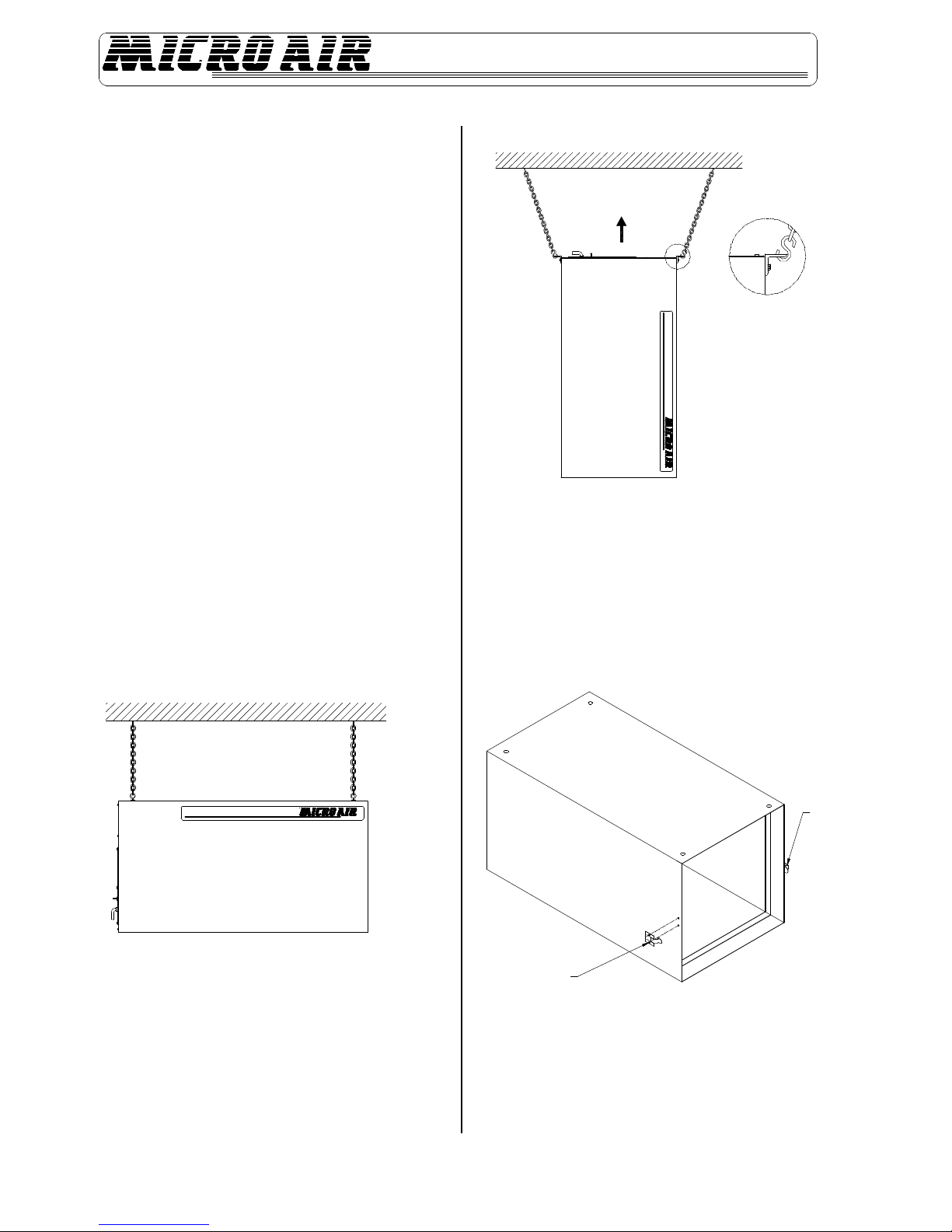
HANGING INSTRUCTIONS
1. Remove the hanger kit from the Owners Manual envelope which
contains four (4) threaded eyebolts and the hex nuts.
2. Thread a nut onto each eyebolt and thread an eyebolt into each of the
four (4) threaded holes in the cabinet. Tighten nuts against the
cabinet.
NOTE: If hanging MX 1800 upside down is required, remove the four (4) ¼”
hex bolts from bottom of cabinet and relocate to top four corners. Then
place the four (4) eyebolts into bottom panel of cabinet.
3. Once eyebolts are secured, the MX 1800 is ready to be hung in an
appropriate location (See FIGURE 1).
4. For vertical installation, use the optional vertical support bracket kit
#34088-04. The support brackets are secured to cabinet by using the
¼-20 hex bolts supplied with the MX 1800 (See Figure 2).
CAUTION: Use strong wire or chain to support the air cleaner. Hang
from structural supports.
NOTE: If a unit is to be installed on brackets against a wall, use brackets
strong enough to hold the unit. Install brackets securely into the wall.
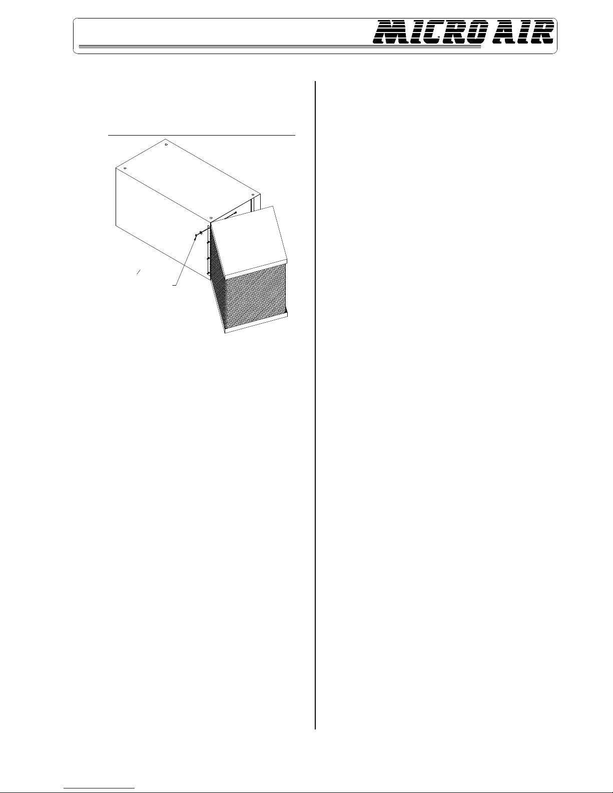
OPTIONAL WRAP AROUND PRE-FILTER
The MX 1800 wrap around pre-filter (WAP) is an optional pre-filter that is
used to increase filter capacity and extend the life of the primary filter. The
WAP is shipped separately from the MX 1800, and therefore requires
assembly prior to installation. Use the following steps to install the WAP:
1. Remove 4” pleated pre-filter from MX 1800.
2. Remove the spring latch from MX 1800 as shown in FIGURE 3.
FIGURE 2
FIGURE 3
REMOVE LATCH
AND HARDWARE
DO NOT REMOVE
THIS LATCH
S-HOOKS AND
CHAIN NOT
PROVIED
3
MX1800
3. Locate WAP next to MX 1800 and secure to cabinet using the ¼”
hardware provided.
NOTE: ¼” nuts and lock washers are located external to the cabinet (See
Figure 4).
FIGURE 4
4. Re-install the 4” pleated pre-filter removed from Step 1.
5. Swing the WAP closed and retain WAP to MX 1800 with remaining
spring latch.
OPERATING INSTRUCTIONS
1. For 115V. 50Hz/60Hz plug is included with power cord. Plug into
outlet. Turn the switch on. The unit should now be operational.
2. For 230V. 50Hz/60Hz, plug is not included with power cord. Attach
250V. plug with desired Nema Configuration. Plug into outlet. Turn
the switch on. The unit should now be operational.
CHANGING FILTERS
CAUTION: Always make sure that the unit is turned off before
changing filters or servicing the unit.
1. The MX 1800 is equipped with a filter change light which indicates
when a filter needs to be replaced.
2. When the light comes on, turn the unit off and remove the pre-filter
only. Replace with a new pre-filter, making sure that the air flow
directional arrow is pointing toward the outlet end. Turn the unit back
on. If the filter change light is off, then the unit is operating properly.
3. If the filter change light fails to go out after replacing the pre-filter, then
the media bag filter also needs to be replaced.
4. To install a new bag filter, turn the unit off. Remove the filter and insert
a new filter.
5. Start the unit. The filter change light should be off, and the unit
operating properly.
FILTER CHANGE LIGHT ADJUSTMENTS
The pressure switch which turns the light on with a differential pressure
increase, is pre-wired on all models. The pressure switch is pre-set at the
factory to indicate (light on) dirty filters and an air flow drop of approximately
67%. If the switch needs readjustment due to a desire for earlier or later
filter changes, or a different combination of filters, this is easily done by
removing the hole plug in the top of the unit for access to the adjustment
screw. Turn the unit on and place a piece of cardboard over the intake,
covering about 80 to 85%of the intake area. With a standard screwdriver,
turn the adjustment screw clockwise until the light goes off, or counter-
clockwise until the light comes on.
For more time between filter changes (less air flow), cover slightly more of
the opening, and for less time between filter changes (more air flow), cover
less of the opening.
During the operation, the filter light coming on indicates that the filters need
attention. Replace only the pre-filter first and see if the light goes out. If not,
replace the bag filter as well.
USE 14" HARDWARE
TO SECURE WAP
HINGE TO MX1800
4
MX1800
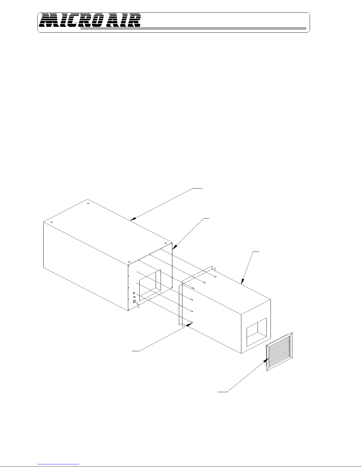
MX 1800 SILENCER INSTALLATION INSTRUCTIONS
CAUTION: THIS INSTALLATION CAN CAUSE EXPOSURE TO LIVE PARTS. DISCONNECT ELECTRICAL POWER TO UNIT BEFORE
PROCEEDING WITH INSTALLATION.
Installation:
1. Unpack and inspect parts for any possible damage incurred during shipping.
2. Remove exhaust grille from unit.
3. Remove screws from exhaust panel, along top, bottom and one (1) side (9 places).
4. Place Silencer over exhaust panel as shown in Figure 5.
5. Align holes on unit with the Silencer, and screw into place using screws previously removed from exhaust panel.
Note: Three (3) new holes will have to be drilled on side of pilot light and switch.
6. Screw grille onto Silencer. Installation is complete.
FIGURE 5
EXISTING SCREWS
EXHAUST GRILLE
SILENCER
EXHAUST PANEL
CABINET ASSEMBLY
5
MX1800
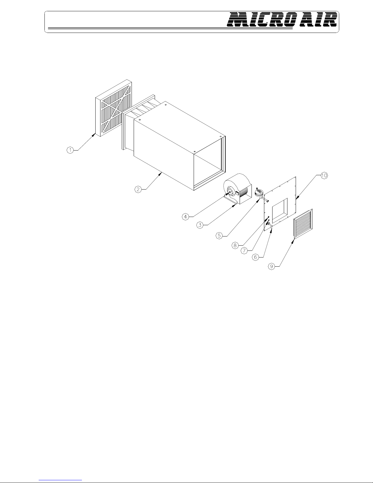
MODEL MX 1800 PARTS LIST
NOTE: 2” Pre-Filters must be used in combinations in order to fill the 4” gap before the main filter.
ITEM PART NO. DESCRIPTION ITEM PART NO. DESCRIPTION
1. P1411 4" Pleated Pre-Filter (See Options Below) 5. 33589-02 Pressure Switch
2. 33536-01 Cabinet Assembly 1/2hp 6. P1363 Cordset (115V)
33536-02 Cabinet Assembly 3/4hp P345 Cordset (230V)
3. P1423 Blower 7. P1354 On/Off Switch
4. P1370 Motor (120V, 1/2hp) 8. P1429 Indicator Light (120V)
P1510 Motor (230V, 1/2hp) P1481 Indicator Light (230V)
P3604 Motor (120V, 3/4hp) 9. P1420 Grille
P3607 Motor (230V, 3/4hp) 10. 33594-01 Access Cover Assembly
REPLACEMENT FILTER LIST
PART NO. DESCRIPTION PART NO. DESCRIPTION
P1411 24" X 24" X 4" Pleated Pre-Filter P1649 24" X 24" X 22" Duo Cube Bag Filter
P1585 24" X 24" X 2" 70% Washable Pre-Filter 33605-01 Wrap Around Pre-Filter Module
P1586 24" X 24" X 2" 96% Washable Pre-Filter 33608-01 Filter Pad Only for WAP
P1440 24" X 24" X 22" 55% Bag Filter 35017-01 Silencer
P1441 24" X 24" X 22" 95% Bag Filter
FIGURE 6

6
MX1800
NOTES:
AIR CLEANERS
Products of Metal-Fab. Inc.
P.O. Box 1138 • Wichtia, Ks 67201
(316) 943-2351 • FAX (316) 943-2717
© 1998 Metal-Fab, Inc. Form No. L804 1/98
5757
Litho in U.S.A.
®
Table of contents
Other Micro Air Corporation Air Cleaner manuals


