Micro Air Corporation IE 1250 User manual
Model IE 1250
OWNER’S MANUAL
AIR CLEANERS ®
CAUTION
Read complete instructions before operating.
Please file for future reference.
IE 1250
2
MODEL IE 1250 SPECIFICATIONS
Input Volts: 120V, 60 Hz
Motor: 3/4 HP, TEAO
Dimensions: 42” L x 19” W x 21” H
Shipping Weight: 150 lbs.
Actual Weight: 130 lbs.
PRE-OPERATING INSTRUCTIONS
1. Cut banding material that holds skid to carboard carton.
2. Remove unit from carboard carton.
3. Inspect power cord and the on/off switch for damage.
4. Open cells access door and inspect cell and ionizer for damage.
HANGING INSTRUCTIONS
The following items are needed for hanging:
?4/0 chain minimum rated at 200 lbs. working load.
?5/16” wrench.
?Bolt cutter.
CAUTION: No less than four (4) chains may be used to suspend
unit from ceiling. Chains should not angle more than 15 degrees.
Hang from structural supports.
1. Remove the eyebolts from the unit.
2. Remove the four (4) screws from the four corners on the top or
bottom of the unit.
3. Screw the nuts provided onto the eyebolts. Then screw the
eyebolts into the unit. Tighten the nuts against the unit to prevent
loosening by vibration.
4. Firmly secure four (4) chains of equal length to a firm, structural
support. Wire of equal or greater strength may be used in lieu of
chains.
5. Raise the unit up to chains and bond eyebolts to chains.
CAUTION: Firm structure must be capable of supporting a
minimum weight of 800 lbs.
ELECTIRCAL CONNECTIONS
A. CORD CONNECTON
For cord connected application, simply plug the cord into an
appropriate A.C. outlet.
B. PERMANENT WIRING
1. Conduit electrical connections should be made by a qualified
electrician and must comply with local electrical codes.
CAUTION: Be sure that designated circuit breaker is off until all
wiring has been completed.
2. Remove blower access door held by four (4) screws.
CAUTION: Be sure that the on/off switch is in the OFF position.
3. Locate desired area for conduit connection and drill hole for
conduit.
4. Route wire through conduit and into electrical compartment.
Disconnect power cord ground wire and replace with green wire
from conduit.
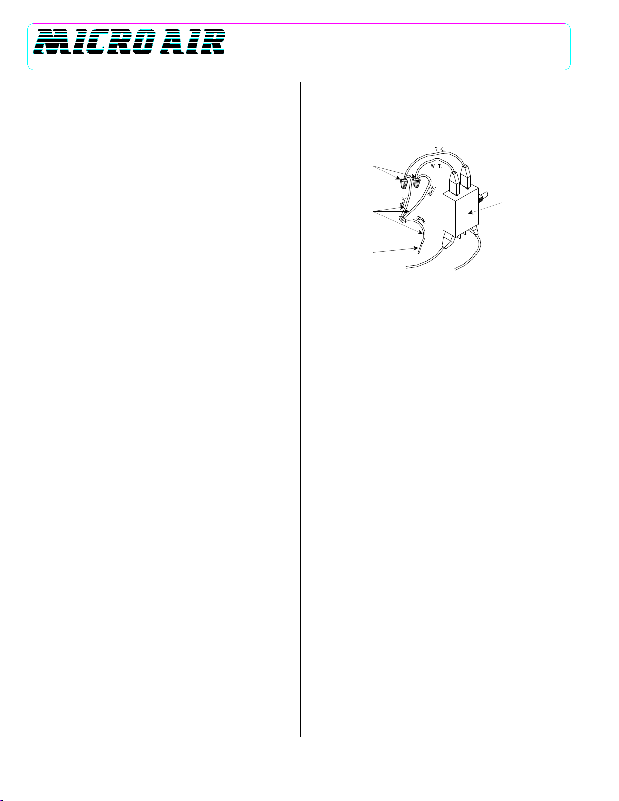
5. Cut power cord six (6) inches from interlock switch, strip insulation
back 1/2” and, using wire nuts, connect black and white wire from
conduit to interlock (Figure 1).
WIRE NUTS
WIRES FROM
POWER SOURCE
TO GREEN
GROUND STUD
INTERLOCK SWITCH
FIGURE 1
6. Remove and discard remaining 9½ ft. of power cord.
7. Replace blower access door and turn unit on.
OPERATION INSTRUCTIONS
1. Turn the switch on. The power lamp should glow.
Note: The cell access door activates an interlock switch when it is
closed.
2. Some initial arcing (popping noise) may occur when the unit is
turned on. This will stop in a few minutes after loose lint and dust
are collected.
3. During normal operation, the power lamp may blink intermittently. If
the lamp stops glowing completely, the cells should be inspected
for excessive moisture or large particles. (See MAINTENANCE
section)
4. The IE 1250 is equipped with a 4-way adjustable exhaust grille.
This can be positioned for the optimum air flow pattern. Adjust grille
up or down, and left or right to achieve desired pattern.
MAINTENANCE
2. Always be sure power switch is turned off before performing any
service to air cleaner.
3. When checking cell and ionizer assemblies, turn unit off and wait
approximately three minutes before attempting to remove
assemblies.
CAUTION: Cell assemblies weigh 27 lbs. each.
3. Open cell access door and note the orientations of the cell, ionizer,
and prefilter. Remove for cleaning.
4. Wash the prefilter, cell and ionizer in a container of hot water, and
ElectriClean or a good industrial detergent that is aluminum safe.
Soak for 15 minutes or more, swishing the parts occasionally.
Rinse thoroughly in clean water, drain, then allow to completely dry
before assembly.
CAUTION: Do not use any caustic or acidic solutions strong
enough to damage aluminum.
5. Make sure the cell is completely dry before installing back into
cabinet.
6. Check the drive belt for tightness and wear.

IE 1250
3
7. Check the blower bearings for wear. Check the blower wheel for
debris and dirt, and clean when necessary.
8. Check all wiring for loose connections or cracked insulation.
TROUBLESHOOTING AND REPAIR
Whenever the air cleaner is not functioning, the neon light on the cabinet
will not be lit. When the unit is operating this light will usually flicker to
some extent. This is normal and does not indicate trouble.
A. If unit is not working (Fan is not running and indicator light is off):
1. Check that fuse or current breaker is closed.
2. Make sure the switch is ON.
Note: If door is not in place when checking, door switch must be held in
manually.
B. If lighted switch is off:
1. Check fuse. If burnt, replace with 0.5 A fuse.
2. Remove cell and ionizer from cabinet. If light comes on upon
activating door switch, the fault is in the ionizer and/or collector cell.
To determine which, first place ionizer in unit. If lamp goes out then
the ionizer is at fault. Repeat procedure with the collector cell.
3. If light is still not operating:
a) Remove the blower access door.
b) Put a neon test light or voltmeter across the two input leads to
check line voltage on primary of high voltage transformer.
c) If correct voltage (120V or 220V ±10V, see Name-Plate) is not
measured, check backward, using wiring diagram, until problem
can be found.
d) Check voltage to light terminals (yellow and green/yellow wires.
See WIRING DIAGRAM) on neon lamp. If corret voltage
(120V±10V) is found but light is out, replace the lighted switch.
e) If there is no voltage, replace power pack. This can be removed by
removing two (2) nuts and lock washers and sliding out the power
pack. Replace new power pack in the same manner.
C. If light is on, but cells are not collecting:
1. Check ionizer for broken ionizer wires and replace if necessary.
Note: If replacement wires are not immediately available, unit will
operate satisfactorily with some of the wires missing until proper wire
can be obtained. Make certain to remove all remnants of the broken
wires.
2. Use an insulated handle screwdriver to cause a short at two
places on the cell between two adjacent collecting plates (first)
and (second) between any ionizing wire and the air flow plate.
The spark at both locations indicates the cell and ionizer are
working. The correct voltage readings are approximately
45000VDC for the plates, 10,000VDC for the wires. A voltmeter
capable of reading 15,000VDC should be used to check for
correct voltage.
3. If no spark is visible, remove the cell and make sure that the cell
contacts are making contact with the contact on unit.
4. To check the cell, connect one side of an ohmmeter to outside
plate of cell and other side of meter to copper contact on the end
of cell. Resistance should read infinity (open circuit). If resistance
is not infinity, see Step 5.
5. Examine cells and ionizers for:
a) Broken ionizing wires.
b) Damaged or bent plates. Straighten bent plate with needle nose
pliers.
c) Excessive dirt accumulation.
D. If the fan motor does not run:
1. Check across the black and white leads on both sides of power
switch with test lead or voltmeter to assure power is on. If power is
on, proceed to Step 2. If power is not on, check main panel fuses
or circuit breakers.
2. If power is on and no voltage is measured on motor side of power
switch, then switch is defective and must be replaced.
WARRANTY
Metal-Fab offers a limited two (2) years warranty (from date of
installation) on all replacement parts due to faulty workmanship and
materials. All patent rights reserved.

IE 1250
4
IE 1250 WIRING DIAGRAM
FIGURE 2
IE 1250
5
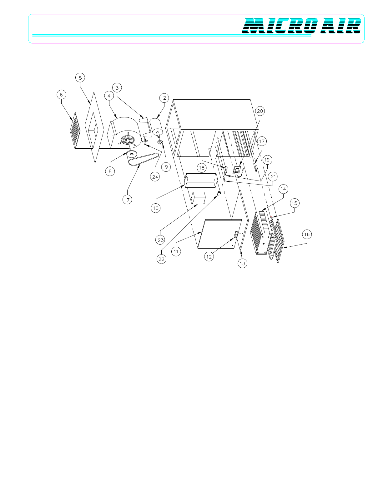
IE 1250 PART LIST
Item Part Number Description Item Part Number Description
1. 30401-01 Cabinet Weldment 17. 30173-01 Ionizer Contact Assembly
2. P1717 Motor, 110/22V, 3/4 HP 18. P1727 On/Off Switch
3. P1725 Motor Mount Braket 19. P1718 Neon Lamp
4. P1361 Blower 20. 30349-03 Cell Contact
5. 30467-01 Access Panel Assembly 21. P1720 Fuse Holder
6. 30465-01 Grille 22. P1702 Interlock Switch
7. P1451 Belt 23. P3500 120V Power Supply
8. P1504 Blower Pulley 24. P1721 Belt Adjuster
9. P1761 Motor Pulley Not Shown P1746 Logo
10. 30407-01 Power Box Weldment Not Shown P1363 Cord Set
11. 30410-01 Blower Access Door Not Shown 33911-01 Ionizer Wire
12. 30505-01 Latch Not Shown P1948 Wiring Label (120V)
13. 30402-01 Door Assembly Not Shown P1733 Switch Label
14. 33917-01 Collector Cell Not Shown P1749 Charcoal Filter
15. 33910-01 Ionizer Not Shown P1752 Media Afterfilter
16. P1703 Prefilter Not Shown 30585-01 Prefilter Screen
FIGURE 3

IE 1250
6
NOTES:
AIR CLEANERS
Products of Metal_Fab. Inc.
P.O. Box 1138 •Wichtia, Ks 67201
(316) 943-2351 •FAX (316) 943-2717
© 2003 Metal-Fab, Inc. Form No. L958 11/03
7339
Litho in U.S.A.
®
Table of contents
Other Micro Air Corporation Air Cleaner manuals

Popular Air Cleaner manuals by other brands

Flexit
Flexit C2 Assembly instructions

Philips
Philips 2000i Series manual

Lifa Air
Lifa Air LIFA HepaClean 2500 Operating and maintenance manual

StressNoMore
StressNoMore E-ZE3 owner's manual

Westinghouse
Westinghouse Accu-Smart WAP811 owner's manual

Oregon Scientific
Oregon Scientific IAD80014-FIL user manual


