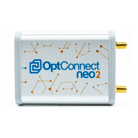
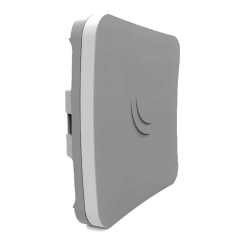
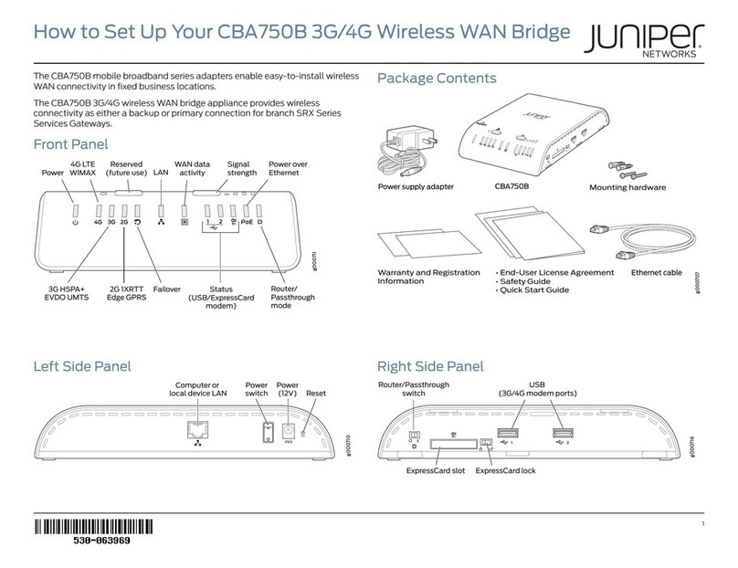
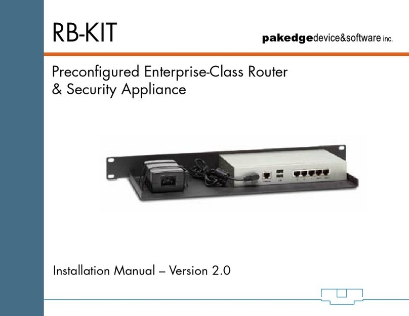
Micro control systems MCS-WIRELESS-3G Installation and operating manual

MCS Total
Solution
for all your
Control
Needs
Energy Efcient and RoHS Compliant
5580 Enterprise Pkwy.
Fort Myers, FL 33905
Ofce: 239-694-0089
Fax: 239-694-0031
www.mcscontrols.com
Package contains the parts
shown below:
Installation and
Reference Guide
Ethernet Cross Over
Cable supplied

MCS-WIRELESS-3G REVISION 1
2
The MCS Commitment is to provide practical solutions for the industries
needs and to be both a leader and partner in the effective use of
microprocessor controls.
Micro Control Systems, Inc.
5580 Enterprise Parkway
Fort Myers, Florida 33905
PH:(239) 694-0089 FAX:(239) 694-0031
www.mcscontrols.com
All information contained within this document is considered to be proprietary information of Micro
Control Systems, Inc. No information or data from this document shall be published, used, repro-
duced, transmitted, or disclosed to others outside your organization without the prior expressed written
consent of Micro Control Systems, Inc. This document and the information contained herein shall be
treated as proprietary. Reasonable provisions shall be provided to ensure that this information remains
proprietary by your employees, agents, and other personnel that may have access to this document.
Copyright ©2014
Date Author Description of Changes
1/6/15 DEW Setup Manual
1/8/15 DEW Added wiring diagram
Revision/Disclaimer Page

MCS-WIRELESS-3G REVISION 1
3
Disclaminer and Revison page ...........................................................................................................2
Table of Contents.................................................................................................................................3
1. MCS- WIRELESS-3G INTERFACE ....................................................................................4
2. INSTALLATION
2.1 Location ........................................................................................................................................5
2.2 Attaching MCS-WIRELESS-3G to mounting bracket ...................................................................5
3. REMOVING FROM THE MOUNTING BRACKET.........................................................6
4. BASIC SETUP
4.1 Quick Start ....................................................................................................................................7
4.2 Connect to Mcs-Magnum..............................................................................................................7
4.3 Network Address on MCS-Magnum .............................................................................................7
4.4 Connection Cross Over Cable ......................................................................................................7
4.5 Power Supply................................................................................................................................7
4.6 Activate your Modem ....................................................................................................................7
5. CONNECTIONS TO MULTIPLE MCS MAGNUMS
5.1 Ethernet Switch.............................................................................................................................8
5.2 Communicating with multiple MCS-MAGNUMS ...........................................................................8
6. WIRING FOR MULTIPLE MCS-MAGNUMS....................................................................9
7. HIGH-GAIN EXTERNAL ANTENNA.................................................................................10
Table of Contents

MCS-WIRELESS-3G REVISION 1
4
1. MCS-WIRELESS-3G INTERFACE
Modem Antennas: The MCS-WIRELESS-3G comes with two modem antennas to
enhance reception for the embedded modem. These antennas are simple to attach
and adjust.
POWER
ON/OFF
MAIN MODEM
ANTENNA
CONNECTOR
AUXILIARHY
MODEM
CONNECTOR
POWER
LED
MODEM
LED
SIGNAL
STRENGTH
LEDS
Power LED:
• Blue = On
• No light = Off Modem LED:
• Green = On and operating normally
• Blinking Green = Connecting
• Amber = No Cellular Connection
• Blinking Amber = Cellular data connection error
• No light = Off
Additional LED Indications:
Factory reset button detected Modem LEDs blink amber twice
Error during USB rmware upgrade Modem LEDs blink red
POWER
PLUG IN
ETHERNET CONNECTIONS
COMPUTERS
OR LOCSAL DEVICES
(LAN DEFAULT
ETHERNET
DATA SOURCE
(WAN DEFAULT
USB
(STANDARD-A)
RESET

MCS-WIRELESS-3G REVISION 1
5
2. INSTALL
CRADLEPOINT COR | USER MANUAL Firmware ver. 5.0.0
© 2014 CRADLEPOINT, INC. PLEASE VISIT HTTP://KNOWLEDGEBASE.CRADLEPOINT.COM/ FOR MORE HELP AND RESOURCES PAGE 14
2.2.1 Attaching the COR to the Mounting Bracket
1) Attach the bracket to the wall or other surface with screws.
NOTE: Screws are not provided because the type of screw required
depends on the mounting surface.
2) Place the router’s edge
against the bottom of the
bracket.
3) Press the router down
firmly, then push it inside
the bracket. It should
latch.
2.2. ATTACHING THE MCS-WIRELESS-3G TO
THE MOUNTING BRACKET
1) Attach the bracket to the wall (indoors, dry location) or other surface with screws.
NOTE: Screws are not provided because the type of screw required depends on the
mounting surface.
CRADLEPOINT COR | USER MANUAL Firmware ver. 5.0.0
© 2014 CRADLEPOINT, INC. PLEASE VISIT HTTP://KNOWLEDGEBASE.CRADLEPOINT.COM/ FOR MORE HELP AND RESOURCES PAGE 14
2.2.1 Attaching the COR to the Mounting Bracket
1) Attach the bracket to the wall or other surface with screws.
NOTE: Screws are not provided because the type of screw required
depends on the mounting surface.
2) Place the router’s edge
against the bottom of the
bracket.
3) Press the router down
firmly, then push it inside
the bracket. It should
latch.
2.1 LOCATION- DRY/INDOORS
2) Place the router’s edge against the bottom of the
bracket.
3) Press the router down rmly, then push it inside
the bracket. It should latch.

MCS-WIRELESS-3G REVISION 1
6
3. REMOVING FROM MOUNTING BRACKET
CRADLEPOINT COR | USER MANUAL Firmware ver. 5.0.0
© 2014 CRADLEPOINT, INC. PLEASE VISIT HTTP://KNOWLEDGEBASE.CRADLEPOINT.COM/ FOR MORE HELP AND RESOURCES PAGE 15
2.2.2 Removing the COR from the Mounting Bracket
From the top of the bracket, press down firmly on the router using your thumb(s) and pull the device out.
3.1 Removing the MCS-WIRELESS-3G from the Mounting Bracket
From the top of the bracket, press down rmly on the router using your thumb(s)
and pull the device out.

MCS-WIRELESS-3G REVISION 1
7
4. BASIC SETUP
4.1 QUICK START
Attach the modem antennas, thumb tight only.
CRADLEPOINT COR | USER MANUAL Firmware ver. 5.0.0
© 2014 CRADLEPOINT, INC. PLEASE VISIT HTTP://KNOWLEDGEBASE.CRADLEPOINT.COM/ FOR MORE HELP AND RESOURCES PAGE 16
3 QUICK START
3.1 Basic Setup
1. Attach the WiFi (right) and
modem antennas.
2. Plug the power supply into
an electrical outlet and
connect it to the router.
3. Make sure the power is
switched on.
O = OFF
I = ON
3.1.1 Activate Your Modem
A wireless broadband data plan must be added to your IBR600/IBR650. Wireless broadband data plans are available
from wireless carriers such as AT&T, Sprint, Verizon, and Vodafone. A new line of service can be added or a data plan
can be transferred from an existing account. You will need the ESN/IMEI (or similar number) from your product label on
your router to add or transfer a line of service.
After adding a data plan to the modem, the modem may need to be activated. To activate the modem:
1. Log in to the router’s administration pages (see Accessing the Administration Pages).
2. Select Internet from the top navigation bar and Modem Settings from the dropdown menu (Internet →Modem
Settings).
3. Find and select the CradlePoint modem.
4. Click Update/Activate. Click Activate in the popup.
4.2 CONNECT TO MCS-MAGNUM
4.4 CONNECTING CROSS OVER CABLE
Connect the end of the supplied CROSSOVER ETHERNET CABLE
to the ETHERNET DATA SOURCE connector on the rear of the
MCS-WIRELESS-3G and the other end to the IO port on the
MCS-MAGNUM CONTROLLER.
4.5 POWER SUPPLY
Plug the power supply into an electrical outlet and connect it to the router.
Make sure the power is switched on.
O = OFF
I = ON
4.6 ACTIVATE YOUR MODEM
A wireless broadband data plan has been added to your MCS-WIRELESS-3G
through Verizon Wireless. THIS IS A FACTORY PRE-INSTALL.
If there are any problems or questions about the intallation of the data plan,
4.3 NETWORK ADDRESS ON MCS-MAGNUM
THE NETWORK ADDRESS FOR YOUR
NEW MCS-WIRELESS-3G HAS BEEN
FACTORY SET AND IS SUPPLIED WITH THE UNIT.
YOU MUST SET THE NETWORK ADDRESS ON YOUR
CONTROLLER TO MATCH THIS FACTORY ADDRESS.
Ethernet Cross Over
Cable supplied

MCS-WIRELESS-3G REVISION 1
8
5.1 ETHERNET SWITCH (NOT SUPPLIED)
An Ethernet switch, provides a central connection in an Ethernet network in which each
connected device has its own dedicated link with full bandwidth. Switches divide LAN
data into smaller, easier-to-manage segments and receive data from the con-
troller. As a result, every port on the switch represents a dedicated 10- or 100-Mbps
pathway. Because users connected to a switch do not have to share bandwidth, a switch
offers relief from the network congestion a shared hub can cause.
5.2 CONNECTING TO MULTIPLE MCS-MAGNUMS
With the NEW MCS-WIRELESS-3G you can connect multiple MCS-MAGNUMS
to the MCS-WIRELESS-3G Modem using an Ethernet Switch (not supplied) that will
enable you to communicate with each MCS-MAGNUM anywhere in the Continental
United States as long as your MCS-WIRELESS-3G is hard wired to an existing
ethernet network. (see wiring diagram on page 9).
5. MUPLIPLE CONNECTIONS

MCS-WIRELESS-3G REVISION 1
9
6.3 WIRING DIAGRAM
6. WIRING FOR MULTIPLE MCS-MAGNUMS

MCS-WIRELESS-3G REVISION 1
10
7. OPTIONAL EXTERNAL ANTENNA
7.1 HIGH-GAIN EXTERNAL ANTENNA
External Antennas are available where better reception is needed.
MUTI-BAND
OMMI-DIRECTIONAL
WIDE-BAND
OMMI-DIRECTIONAL
Dual-Band Omni-
Directional Antenna

MCS-WIRELESS-3G REVISION 1
11
NOTES

Providing HVAC/R Control Solutions Worldwide
5580 Enterprise Pkwy. Fort Myers, FL 33905
Ofce: (239) 694-0089
Fax: (239) 694-0031
www.mcscontrols.com
Table of contents
