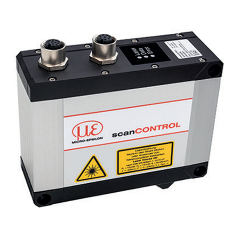
MICRO-EPSILON scanCONTROL2800 User manual

O
C
MICRO-EPSILON
By far the better solution
SENSORS & SYSTEMS
2D/3D Line Triangulation
Instruction Manual
scanCONTROL2800/2810

MICRO-EPSILON
MESSTECHNIK
GmbH & Co. KG
Königbacher Strasse 15
D-94496 Ortenburg
Tel. +49/85 42/1 68-0
Fax +49/85 42/1 68-90
e-mail [email protected]
www.micro-epsilon.com
Certified acc. to DIN EN ISO 9001: 2000

MICRO-EPSILON
X9751109-B060097MSC
Contents
1. Safety ...................................................................................5
1.1 Symbols Used............................................................................................. 5
1.2 Warning Information .................................................................................... 5
1.3 Information on CE Marking ......................................................................... 6
1.4 Proper Use .................................................................................................. 6
1.5 Proper Environment .................................................................................... 7
2. Laser Safety ......................................................................... 7
2.1 Laser Class 2M ............................................................................................ 7
2.2 Laser Class 3B ............................................................................................ 8
3. Functioning Principle, Technical Data .............................. 9
3.1 Brief Description.......................................................................................... 9
3.1.1 Measurement Principle ................................................................................ 9
3.1.2 System Set-up ........................................................................................... 10
3.1.3 Special Performance Features .................................................................. 10
3.2 Technical Data ........................................................................................... 11
3.3 Connections .............................................................................................. 12
3.3.1 Analog Output........................................................................................... 12
3.3.2 Communication ......................................................................................... 12
3.3.2.1 FireWire (IEEE 1394) ................................................................................. 12
3.3.2.2 RS232/RS422 ............................................................................................ 12
3.3.3 Switching Signals ...................................................................................... 12
3.3.4 Synchronous and Trigger Signals ............................................................. 12
3.3.5 Laser Switch-off ......................................................................................... 12
3.3.6 Video Output ............................................................................................ 12
3.4 Operating and Display Elements .............................................................. 13
3.4.1 Key Switch ................................................................................................ 13
3.4.2 Reset Button ............................................................................................. 13
3.4.3 Mode Button ............................................................................................. 13
3.4.4 LED Indicators........................................................................................... 13
4. Delivery .............................................................................. 14
4.1 Items Included ........................................................................................... 14
4.2 Storage ..................................................................................................... 14
5. Mounting ........................................................................... 14
5.1 Attachment and Mounting of the Sensor .................................................. 14
5.2 Attachment and Mounting of the Controller .............................................. 19
5.3 Requirements on the Cable and Cable Connection .................................. 20
6. Measurement Setup and Putting into Operation ...........20
6.1 Preparing for Operation, Power Supply .................................................... 20
6.2 Operation of the scanCONTROL28x0 without a PC .................................. 21
6.2.1 Displays .................................................................................................... 21
6.2.2 Analog Outputs ......................................................................................... 21
6.2.3 Measurement Conversion for Analog Distance Values (z values) .............. 22
6.2.4 Measurement Conversion for Analog Transverse Coordinates (x values) .. 22
6.3 Coupling Sensors via the FireWire Interface .............................................. 23
6.3.1 General Properties of the IEEE 1394 (FireWire) Bus System ..................... 23
6.3.2 FireWire Configuration .............................................................................. 23
6.3.3 DCAM-Standard: ....................................................................................... 24
6.4 Output Circuit of the Error and Mode Outputs .......................................... 24
6.5 Synchronization and Triggering ................................................................ 25
6.6 Laser Switch-off and Mode Inputs ............................................................. 25
6.7 Analog Outputs ......................................................................................... 26
6.8 Video Output ............................................................................................ 26
MICRO-EPSILON
X9751109-B060097MSC
7. Serial Interfaces ................................................................ 27
7.1 RS232 ....................................................................................................... 27
7.2 RS422/485 ................................................................................................. 27
7.3 Pin Assignment ......................................................................................... 27
7.4 Digital Measurement Output ..................................................................... 27
8. Information for Operation................................................. 28
8.1 Measuring Rate ......................................................................................... 28
8.2 Automatic Control of the Exposure Time .................................................. 28
8.3 Measuring Field Selection and Calibration ..................... 29
8.3.1 Measuring Field ........................................................................................ 29
8.3.2 Calibration................................................................................................. 31
8.4 Error Effects ............................................................................................... 32
8.4.1 Degree of Reflection on the Target Surface ............................................... 32
8.4.2 Color Differences ....................................................................................... 32
8.4.3 Temperature Effects ................................................................................... 32
8.4.4 Extraneous Light ....................................................................................... 32
8.4.5 Mechanical Vibrations ............................................................................... 32
8.4.6 Surface Roughness ................................................................................... 33
8.4.7 Shadows ................................................................................................... 33
8.4.8 Multiple Reflections ................................................................................... 34
8.5 Laser Power .............................................................................................. 34
9. Warranty ............................................................................ 35
10. Service, Repair .................................................................. 35
11. Software .............................................................................36
12. Decommissioning, Disposal ............................................ 36
13. Annex ................................................................................. 36
13.1 Accessory ................................................................................................. 36
13.2 Possible Measuring Fields ........................................................................ 37
13.3 Error Coding ............................................................................................. 38
13.4 Sensor Inspection Log (sample) ............................................................... 39

MICRO-EPSILON
X9751109-B060097MSC 5
1. Safety
1.1 Symbols Used
The following designations are used in this operating manual:
DANGER! - immediate danger
WARNING! - possibly a dangerous situation
i
IMPORTANT! - application tips and information
1.2 Warning Information
Avoid unnecessary laser radiation to be exposed to the human body
- Switch off the sensor for cleaning and maintenance.
- Switch off the sensor for system maintenance and repair if the sensor is
integrated into a system.
• Caution - use of controls or adjustments or performance of procedures other
than those specified herein may result in hazardous radiation exposure
• Avoid impacts and shocks on the sensor and controller.
ÞDamage or failure of the sensor and / or of the controller.
• Voltage supply must not exceed specified limits.
ÞDamage or failure of the controller and / or of the sensor.
• Voltage supply and the display/output device must be connected
according to safety regulations for electrical operating equipment.
ÞInjury hazard
ÞDamage or failure of the sensor and / or of the controller.
• Protect the sensor cable from damage
ÞDestruction of the sensor
ÞFailure of the measurement instrument.
• Avoid the continuous effect of splashing water on the sensor (and the
controller).
ÞDamage or failure of the sensor and controller.
•Only operate sensors on controllers with the same serial number.
ÞLoss of the specified technical data.
•The controller housing may only be opened by authorized persons, (see also
Chap. 9).
ÞDamage to or failure of the controller.
Safety
• Caution - use of
controls or adjustments
or performance of
procedures other than
those specified herein
may result in hazardous
radiation exposure

MICRO-EPSILON
X9751109-B060097MSC 6
1.3 Information on CE Marking
The following applies to the scanCONTROL28x0 measurement system:
EU Directive 89/336/EEC
Products which bear the CE mark satisfy the requirements of the EU Directive 89/
336/EEC "Electromagnetic compatibility" and the harmonized European
standards (EN) listed in it.
The EU declaration of conformance is kept available for the responsible
authorities according to the EU Directive, Article 10, at
MICRO-OPTRONIC MESSTECHNIK GmbH
Lessingstraße 14
D-01465 Langebrück
The measurement system is designed for use in the industrial field and fulfills the
requirements according to the standards
• EN 55011 Class B /05.200 Emitted interference
• EN 61 000-6-2 /08.2002 Immunity to interference
The measurement system fulfills the requirements when the guidelines described
in the operating manual are followed during installation and operation.
1.4 Proper Use
• The scanCONTROL 28x0 measurement system has been designed for
application in the industrial and laboratory fields.
• It is employed for
- Profile measurement
- Quality monitoring and inspection of dimensions
• The measurement system may only be operated within the limits
specified in the technical data (see Chap. 3.2).
• It must be used such that with malfunctions or total failure of the sensor,
no persons are put in danger nor machines damaged.
• With safety-related applications additional precautions must be taken
for safety and for the prevention of damage.
Safety

MICRO-EPSILON
X9751109-B060097MSC 7
1.5 Proper Environment
• Protection class Sensor: IP64 (applies only with sensor cable connected)
• Protection class controller: IP50
• The level of protection does not apply to optical inputs, because when they
become dirty, impairment or failure of the function results.
• Operating temperature: 0 ... 50 °C
• Storage temperature: -20 ... 70 °C
• Air humidity: 5 - 95 % (non-condensing)
• Ambient pressure: Atmospheric pressure
• EMC: According to
EN 55011 Class B /05.200 Emitted interference
EN 61 000-6-2 /08.2002 Immunity to interference
2. Laser Safety
The scanCONTROL28x0 sensors operate with a semiconductor laser having a
wavelength of 655 nm (visible/red). The laser operation is indicated visually by the LED
on the sensor and on the controller.
When operating the scanCONTROL28x0 sensors, the relevant regulations according to
EN 60825-1 (IEC 60825, Part 1 of 11/2001) and the applicable accident prevention
regulations must be followed.
The housing of the scanCONTROL28x0 optical sensors must only be opened by
authorized persons, (see also Chap. 9). For repair and service, the sensors should
always be returned to the manufacturer.
2.1 Laser Class 2M
Sensors with a maximum laser power up to 15 mW (see Chap. "Technical Data") are
classified in Laser Class 2M (IIM).
Accordingly, the following applies:
With laser equipment of the Class 2M, the eye is not put in danger during random,
short-term exposure to the laser radiation, i.e. exposure duration up to 0.25 s.
A direct glimpse into the beam can be dangerous if the eye-closure reflex is
deliberately suppressed, e.g. during adjustment. Direct viewing into the beam with
optical aids, e.g. a magnifying glass, is dangerous.
Laser equipment of the Class 2M can be employed without further protective measures,
when deliberate viewing into the laser beam or into a beam reflected by mirrors is not
longer than 0.25 s.
Since generally the presence of the eye-closure reflex should not be assumed, one
should close the eyes or immediately turn away if the laser radiation impinges on the
eye.
Lasers of Class 2M are not subject to notification and a laser protection officer is not
required. Mark the laser area recognizable and everlasting.
Safety
i
IMPORTANT!
The protection class is
limited to water (no
penetrating liquids or
similar).
i
IMPORTANT!
Follow laser protection
regulations.
WARNING!
Do not intentionally look
into the laser beam.
Consciously close the
eyes or turn away if the
laser radiation impinges
on the eye.

MICRO-EPSILON
X9751109-B060097MSC 8
The following information label should be fitted to the sensor housing (front and back):
IEC label Only for USA
The laser labels for Germany are already printed on. The labels for the EU area and the
USA are enclosed and must be fitted by the user for the region applicable in each case
before the equipment is put into operation.
2.2 Laser Class 3B
Sensors with a maximum laser power up to 50 mW (see Chap. "Technical Data") are
classified in Laser Class 3B (IIIB).
Accordingly, the following applies:
The available laser radiation is hazardous for the eyes and usually for the skin also.
Looking directely into the laser beam is hazardous for the eyes. Also reflections on
shining or mirroring surfaces can be hazardous the eye.
Hazards to the skin through the available laser radiation is given by class 3B (IIIB) laser
equipments if the values of the maximum permissible exposure are exceeded.
The user is responsible that the accident prevention regulations are observed.
Class 3B (IIIB) laser sensors are notifiable and a laser protection officer is required
either. Mark the laser area recognizable and everlasting. During operation the laser area
has to be restricted and marked.
If the sensor is on the laser output can be reduced to 15 mW with the software. Reducing
the laser output to 1 mW is not possible.
Reducing the laser output from 50 mW to 15 mW with a software affects not the
laser class!
The following information label should be fitted to the sensor housing (front and back):
IEC label Only for USA
The laser labels for Germany are already printed on. The labels for the EU area and the
USA are enclosed and must be fitted by the user for the region applicable in each case
before the equipment is put into operation.
Laser Safety
i
IMPORTANT!
If both information
labels are hidden in the
installed state, the user
must ensure that additi-
onal labels are fitted at
the point of installation.
WARNING!
Do not intentionally look
into the laser beam.
Consciously close the
eyes or turn away if the
laser radiation hits the
eye.
i
IMPORTANT!
If both information labels
are hidden in the installed
state, the user must
ensure that additional
labels are fitted at the
point of installation.

MICRO-EPSILON
X9751109-B060097MSC 9
Laser Safety
Beam attenuator
Laser products certified as Class 3B products (EN 60825-1) require a beam attenuator
other then the key-operated control. The beam attenuator prevents access to all laser
and collateral radiation in excess of the emission limits of class 1.
To open or close the aperture please follow the steps below:
•unscrew the knurled screw,
•change the attenuator position,
•tighten the knurled screw.
The laser aperture must be open during measurement.
Fig. 2.1: True reproduction of the sensor with its actual location of the warning label
3. Functioning Principle, Technical Data
3.1 Brief Description
3.1.1 Measurement Principle
The scanCONTROL2800, 2810 sensor operates according to the principle of optical
triangulation (light intersection method):
• A laser line is projected onto the target surface via a linear optical system.
• The diffusely reflected light from the laser line is replicated on a CMOS array by a
high quality optical system and evaluated in two dimensions.
Laser spot Laser spot
Fig. 1a: scanCONTROL, beam
attenuator masks aperture.
Fig. 1b: scanCONTROL, beam
attenuator in measuring position.

MICRO-EPSILON
X9751109-B060097MSC 10
The laser line triangulation corresponds in principle to the triangulation of a laser point.
In addition, during the measurement a row of lines are simultaneously illuminated by
the laser line. Apart from the distance information (Z axis), the exact position of each
point on the laser line (X axis) is also acquired and output by the system.
3.1.2 System Set-up
The scanCONTROL28x0 measurement system consists of a compact sensor and an
intelligent controller which are connected together via an extendable connecting cable.
The controller can output the measurements of the two axes or, optionally, coupled
values. The user can also select from several evaluation functions (modes).
3.1.3 Special Performance Features
• scanCONTROL features speed with simultaneously high measurement accuracy. A
special line-scanning optical system ensures uniform illumination of the measuring
field.
• The CMOS array is arranged in the sensor head according to the Scheimpflug
condition which facilitates uniform image focusing over the whole depth
measurement range (z axis).
• In conjunction with saved configurations scanCONTROL 28x0 measurement
system is also capable of functioning without a PC. The measurements are either
output via two analog outputs (x-z profile or parameters) or can interact with a PLC
via the digital inputs/outputs.
Advantages of the used CMOS array (difference to normal video matrices):
• The high resolution CMOS array has 1024 x 1024 pixels and freely selectable access
to preselected areas. Consequently, the geometry of the measuring field (height Z
and width X) can be varied and can be adapted to the measurement application.
• With fast moving objects a high profile accuracy is achieved for the complete
profile using a global shutter (high speed shutter).
• The array enables the simultaneous exposure and reading out of theprevious image.
As a result, exposure can be for longer with the same profile frequency and hence
also dark objects can be measured at high speed.
Further features
• External synchronization and triggering.
• Two serial interfaces (RS232 and RS422) for communication with PLCs or PCs.
• FireWire connection (IEEE 1394) as fast standard link to the PC.
• Video output for adjustment purposes.
• The automatic control of the illumination time enables consistent measurement
results with changing surfaces. This function can be switched off on request.
i
IMPORTANT!
Sensor and controller
form one unit. For
accurate measurements
only use components
assigned with the same
serial number.
Light source
Receiver
CMOS array
Target
Z-Axis
X-Axis
Fig. 3.1: Scanning a profile
Functioning Principle, Technical Data

MICRO-EPSILON
X9751109-B060097MSC 11
Functioning Principle, Technical Data
3.2 Technical Data
All specified data applies to metallic mattfinished surfaces.
1) For standard measurement range, slight displacement of the measuring field possible (depends on sensor)
2) 1024 points per profile with extended measurement range and 128,000 points/s (optional 256,000 points/s) only.
3) Only applies to values preprocessed in the controller, e.g. width, height, glue bead area, edge detection, groove width, angle etc.
4) Preassigned, other functions possible, e.g. encoder.
5) The data apply to the sensor.
Model LLT28x0-25 LLT28x0-100
Standard measurement ranges, typical values (±5 %) for extended measurement range in brackets
Measurement range, z axis 25 (55) mm 100 (245) mm
Start of measurement range (SMR) 62.5 (50) mm 145 (115) mm
Reference distance, midrange 75 (82.5) mm 195 (235) mm
End of measurement range (EMR) 87.5 (105) mm 245 (360) mm
Resolution z axis 1 0.04 % 10 µm 40 µm
Linearity z axis (3 ) 10.2 % 50 µm 200 µm
at SMR 13 (23) mm 30 (50) mm
at EMR 18 (41) mm 50 (140) mm
Aperture angle of the laser line
Resolution x axis
at SMR 60 µm 120 µm
at EMR 80 µm 200 µm
Resolution profile parameters
Profile frequency (profiles/second)
Measurement rate (measuring points / s)
Light source
Laser class (EN 60825-1)
Laser switch-off
Permissible extraneous light (fluorescent lamp)
Operating temperature
Storage temperature
Electromagnetic compatibility
(EMC)
Vibration (acc. to IEC 60068-2-6) 5
Shock (acc. to IEC 60068-2-29) 5
Sensor dimensions (without cable) (LxWxH) mm 109 x 64 x 44 125 x 64 x 44
Sensor weight (without cable) 350 g 400 g
Sensor connecting cable, standard length
Controller dimensions (without connectors)
Controller weight (without cable)
Output analog
preassigned: x and z axis,
alternatively: profile parameters 3
Interfaces
Digital inputs 4
Digital outputs 4
Power supply
Laser diode 655 nm, 15 mW (optional 50 mW)
Sync-In, Remote laser ON/OFF, User mode, Encoder
± 10 V (16 Bit, up to 150 kHz)
Rl= 50 Ohm, Imax = 5 mA
Class 2M (optional: 3B)
Sensor IP 64, controller IP40
Remote input and key switch
15 g / 6 ms
Measurement range x axis
RS232 / RS422; 115,200 Baud
30 °
256 / 512 / 1024 2, optional 64 / 128 points/profile
10,000 lx
-20...70 °C
3x IEEE 1394 („FireWire“), 400 MBit/s,
DCAM 1.30 Standard
2 m
L x W x H 278 x 187 x 107 mm
3.5 kg
Linearity x axis (3 ) 1
0.4 %
Serial (measurements and control commands)
Switching signals
24 VDC ± 15 %; 0.5 A
up to 1000 profiles/s (optional up to 4000 profiles/s)
up to 256,000 measuring points / s
0...50 °C
Sync-Out, error, user mode (2x)
EN 61000-6-3 Spurious emission
EN 61000-6-2 Resistance to disturbance
0.05 %
Protection class
2 g / 20 ... 500 Hz
s
s

MICRO-EPSILON
X9751109-B060097MSC 12
3.3 Connections
3.3.1 Analog Output
The two assigned profile signals for height (Z direction) and width (X direction) can be
taken from the 4-pole connecting socket. If optional processing has been activated,
profile parameters (e.g. hight, width area etc. of a glue bead) are output on the analog
output. In conjunction with saved configurations, the scanCONTROL 28x0 measurement
system is also capable of functioning without a PC.
As deliverd the sensor supplies 400 profiles / s for 1 ms exposure time in the standard
measurement range. Other configurations can be saved.
3.3.2 Communication
3.3.2.1 FireWire (IEEE 1394)
The FireWire port is the standard link to the PC. Three equal FireWire ports with up to
400 Mbit/s are present on the controller. The high data rate enables the cascading of a
number of controllers or digital video cameras on one IEEE 1394 PC interface. In this
case both line and star-shaped connection structures can be realized which must be
connected free of loops. The controller does not supply any operating voltage to the
1394 connection sockets.
3.3.2.2 RS232/RS422
Programs can be loaded and measurements transferred via the RS232 or the RS422
interface. The RS232 connection on the controller can be connected to the COM
interface of the PC via a commercially available 9-pole extension cable (plug - socket).
Only one of these interfaces can be active. The lower data rate permits only a lower
measurement rate compared to FireWire.
3.3.3 Switching Signals
Three outputs and one input are available. All switching signals are opto-decoupled.
In the standard setting they have the following functions:
• Input "Mode": Function as for Mode button,
• Output "Error": error is serial coded, see Chap. 13.3
• Output "Mode 1" and "Mode 2": Operating mode (in binary code).
3.3.4 Synchronous and Trigger Signals
Individual profiles (scans) can be triggered or a number of sensors synchronized
together via the synchronous connection socket. Other functions are possible as
options.
3.3.5 Laser Switch-off
Pins 3 and 13 on the synchronous socket are used for the external safety switch-off of
the laser. A switching transistor with an open collector (e.g. in an optocoupler) or also
a relay contact are suitable for switching.
Laser Class 2M (IIM) sensors: The switch-off can be configured with open or
connected pins (default setting).
Laser Class 3B (IIIB) sensors: The laser is off if the pins are open. Therefore switch-off
is configured with open pins 3 and 13 and can not be changed.
3.3.6 Video Output
The video signal is only provided for adjustment and test purposes and can be
activated by software (see FireWire documentation).
Functioning Principle, Technical Data
i
IMPORTANT!
The analog connecting
cable 3 m, "C2800-3", is
available as an optional
accessory from Micro-
Epsilon Messtechnik.

MICRO-EPSILON
X9751109-B060097MSC 13
Functioning Principle, Technical Data
3.4 Operating and Display Elements
3.4.1 Key Switch
The key-operated switch interrupts the flow of current to the laser sensor for
maintenance purposes. When the switch is in the "Off" position, the associated green
LED goes out and the sensor plug can be withdrawn.
3.4.2 Reset Button
On pressing the Reset button a program restart is initiated in the controller,
corresponding to a "power-on reset".
3.4.3 Mode Button
The saved operating modes can be selected in a cyclic manner with the "mode"
button. Also, the parameters configured by software can be permanently saved in the
controller with the Mode button (see Chap. 11).
3.4.4 LED Indicators
Light emitting diodes on the controller signal:
power on: The green "power on" LED lights when the operating voltage is applied.
laser on: The green LED is out when the laser is off (see Chap. 3.3.5).
The LED "laser on" also may light, if no sensor is connected.
error: The red error LED signalizes different error states by different blinking
schemes (see Chap. 13.3).
control: Communication with PC. The green LED also blinks,
• long during an active data transmission and
• short for control access.
mode 1 / 2: The yellow LEDs indicate the current
operation mode.
A green light emitting diode on the sensor signals "laser on".
Analog output
Connections to PC Switch, synchron
and trigger signal,
Laser ON/OFF
Video output
Mode button
Laser ON/OFF
Power
Reset button Sensor
Serial interfaces
Fig. 3.2: Front view of the controller
DEL noitarepO
edoM
2edom 1edom
tluafeD
1edoM
2edoM
3edoM

MICRO-EPSILON
X9751109-B060097MSC 14
4. Delivery
4.1 Items Included
Standard:
1 sensor LLT 28x0
1 controller
1 instruction manual
1 power supply cable 3 m long "PC2800-3"
1 analog output plug, 4-pole, (ODU, Series MiniSnap L,
Order no. S11L0C - T04MJGO - 7200).
1 data medium (CD) with ICONNECT supplementary modules and
demonstration programs (under Windows 2000 / XP).
1 FireWire connecting cable 1.5 m.
1 software manual "Sensor edition" (scanCONTROL2810 only)
Optional accessories:
• Sensor extension cable, "CE2800-3" (3 m long) or "CE2800-8" (8 m long)
• PCI interface card Matrox Meteor II/1394 with 12 V power supply cable.
• 15-pole sub-D plug with shielded recessed grip for synchronous socket.
• Analog connecting cable 3 m, "C2800-3".
Please check the shipment after unpacking for completeness and damage in
transit. If items are damaged or incomplete, please contact the manufacturer or
supplier.
4.2 Storage
Storage temperature: -20 to +70 °C
Air humidity: 5 - 95% (non-condensing)
5. Mounting
5.1 Attachment and Mounting of the Sensor
The sensor can be mounted in three different ways:
1. with three through holes for M4 screws from the side,
2. with three M4 threaded holes on the front and
3. with three M4 threaded holes on the top (cable entry!).
The fixing dimensions can be taken from the dimensional drawings in the annex.
The scanCONTROL28x0 is an optical sensor with which measurements in the μm
range can be taken. Therefore, treat it with care during fitting and operation.
When selecting mounting screws, pay attention to the depth of the blind holes
to avoid damaging the threads due to screws bottoming out. The tightening
torque should not be selected too high.
Delivery
Fig. 4.1: Standard delivery of a
scanCONTROL 28x0

MICRO-EPSILON
X9751109-B060097MSC 15
Mounting
0
4
22
40
0
4,5
59,5
64
Threaded hole
M4 max. 6 deep
0
22
11
33
44
0
17,5
46,7
72
Wi ndow, l as er
ø 9 free
Window, optics
21x18 free
LED
Hole ø 4,5
0
4,5
64
59,5
60,5
(78)
0
5
38
104
108,5
18 AF
0
4
22
40
0
5
104
54,5
Mounting hole
M4 / 6 deep
Fig. 5.1: Dimensional drawing scanCONTROL28x0-25

MICRO-EPSILON
X9751109-B060097MSC 16
Mounting
Standard measuring range
Extended measuring range
1) Typical values, displacement
of the measuring field depends
on the sensor,
tolerance appr. 5 °.
3 (.12)
50 (1.97)55 (2.17)
62.5 (2.46)25 (.98)
0
17.5 (.69)
48 (.71)
69 (2.72)
50 (1.97) 1
55 (2.17) 1
62.5 (2.46)25 (.98)
6 (.24)
18 (.71)
22 (.87)
30 °
23 (.91) 1
13 (.51) 1
18 (.71) 1
41 (1.61) 1
Laser line
Fig. 5.2: Measuring field assignment scanCONTROL28x0-25

MICRO-EPSILON
X9751109-B060097MSC 17
Mounting
0
17,5
97,7
72,4
0
11
33
22
44
Window, laser
ø 9 free
Window, optics
21x18 free
LED
0
4
22
40
0
4,5
59,5
64
Threaded
hole M4
max. 6 deep
0
4,5
59,5
60,5
64
(78)
0
5
62
125
120,5
18 AF
Hol e ø 4, 5
0
5
79,5
120,5
0
4
22
40
Mounting hole
M4 / 6 deep
Fig. 5.3a: Dimensional drawing scanCONTROL28x0-100
Fig. 5.3b: LLT 28x0-100 with mounting and threaded holes
3 x M4
threaded holes
3 x M4 threaded holes
3 x ø4.5 mounting holes

MICRO-EPSILON
X9751109-B060097MSC 18
Standard measuring range
Extended measuring range
1) Typical values, displacement
of the measuring field depends
on the sensor,
tolerance appr. 5 °.
Mounting
Fig. 5.4: Measuring field assignment scanCONTROL28x0-100
3 (.12)
115 (4.53)245 (9.65)
145 (5.71)100 (3.94)
0
17.5 (.69)
74 (2.91)
95 (3.74)
115 (4.53) 1
245 (9.65) 1
145 (5.71)100 (3.94)
6 (.24)
18 (.71)
22 (.87)
50 (1.97) 1
140 (5.51) 1
30 °
Laser line
50 (1.97) 1
30 (1.18) 1

MICRO-EPSILON
X9751109-B060097MSC 19
Mounting
5.2 Attachment and Mounting of the Controller
The controller can be mounted using four M4 DIN 84 screws instead of the rubber feet,
see dimensional drawings in the annex. To do this, the corner protection caps should
be pulled off carefully to the side (e.g. with a screwdriver) and plugged on again after
mounting. The controller should be mounted such that the function-indicating LEDs are
not hidden. When mounting the controller particular care is needed in the routing of the
cables and their strain relief.
Fig. 5.5: Dimensional
drawing controller
scanCONTROL28x0
laser off
on
1394 1394 1394 RS 232 RS 422
videoanalog
laser on
powe r o n
error
sensor
cont rol
mode
mode 2
mode 1 3
reset
24VDC
synchron
246 (9.69)
105.5 (4.15)
107 (4.21)
278 (10.9)
178 (7.01)
186.8 (7.35)
146 (5.75)
4 rubber feet for mounting
holes dia. 6.0 mm

MICRO-EPSILON
X9751109-B060097MSC 20
i
IMPORTANT!
The sensor may only be
plugged and unplugged
with the power switched off,
i.e. with the operating
voltage switched off or with
the keyswitch in the "Off"
position (Laser off).
5.3 Requirements on the Cable and Cable Connection
Supply voltage:
• 24 VDC (±15 %, max. 500 mA)
• The cable shielding is connected to the connectors case. The shielding of the
power supply cable must be connected to the protective earth (PE).
Analog output:
• Recommendation: 2-way coaxial cable of type UNITRONIC LiYCY-CY 2 x 0.25.
Maximum cable length 10 m.
• With longer cable lengths the effect of electromagnetic interference fields on the
signal can lead to measurement uncertainties. To reduce the interference voltages a
1 nF capacitor can, if necessary, be wired in parallel to the input of the evaluation
unit.
• Optionally, the analog connecting cable 3 m, "C2800-3" , can be used.
• Cable is double shielded and the outer shielding is connected to the plug
enclosure.
• At the user's end the outer shielding should be connected to the earth conductor (PE).
Error output, synchronization:
• Strands in the cable should be twisted.
• Cable is shielded. The cable shielding is connected to the shielded connector.
FireWire connections:
• Use the recommended standard connecting cable (optional accessory).
• Connect the connecting cable to the PC only after concluding the driver
installation, because otherwise problems can occur with the driver installation.
6. Measurement Setup and Putting into Operation
6.1 Preparing for Operation, Power Supply
The sensor and controller should be mounted according to the mounting instructions
(Chap. 5). Connect the sensor and the controller to the sensor cable. Connect the
controller to the following display or monitoring units and to the power supply.
The plugs for the operating voltage, sensor and analog outputs are fitted with a push-pull
lock. To release them pull only on the grip section.
Connecting with the power supply
WARNING!
When employing power
supply units, always use
VDE-compliant and
tested equipment.
Mounting
Fig. 6.1: View: Solder-pin side,
male cable connector
Tab. 6.1: Pin assignment PC2800-x
MICRO-EPSILON recommends the use of the optional availbale PS2010 power supply
unit with snap rail mounting, input 230 VAC (115 VAC), output 24 VDC / 2.5 A.
Connect the screen of the power supply cable with the safety earth conductor.
niP tnemngissA roloC
x-0082CP
1 CDV42+rewoP der
2 DNG-rewoP
)CDV0(
eulb
gnisuoH neercS kcalb
1
2
i
IMPORTANT!
The minus pole of the
supply voltage (Power
GND) is electrically isolated
from the system ground.
This manual suits for next models
1
Table of contents
Other MICRO-EPSILON Scanner manuals

MICRO-EPSILON
MICRO-EPSILON scanCONTROL 2500 User manual

MICRO-EPSILON
MICRO-EPSILON scanCONTROL 29 Series User manual

MICRO-EPSILON
MICRO-EPSILON scanCONTROL 30 Series User manual

MICRO-EPSILON
MICRO-EPSILON scanCONTROL LLT3000-430 User manual

MICRO-EPSILON
MICRO-EPSILON scanCONTROL 3000 User manual

MICRO-EPSILON
MICRO-EPSILON scanCONTROL 30 Series User manual

MICRO-EPSILON
MICRO-EPSILON scanCONTROL 2910 User manual

MICRO-EPSILON
MICRO-EPSILON scanCONTROL 3010/BL User manual

MICRO-EPSILON
MICRO-EPSILON scanCONTROL 30 Series User manual