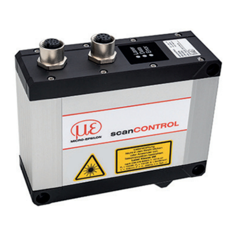
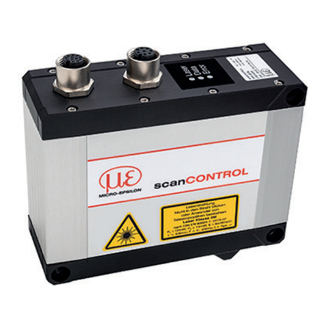
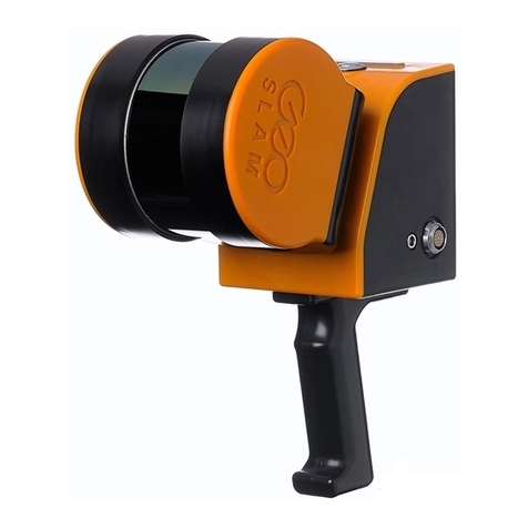
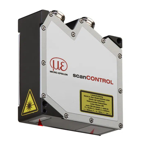
MICRO-EPSILON scanCONTROL LLT3000-430 User manual

Operating Instructions
scanCONTROL 30xx
LLT3000-25
LLT3000-25/BL
LLT3000-50
LLT3000-50/BL
LLT3000-100
LLT3000-100/BL
LLT3000-200
LLT3000-430
LLT3000-600
LLT3010-25
LLT3010-25/BL
LLT3010-50
LLT3010-50/BL
LLT3010-100
LLT3010-100/BL
LLT3010-200
LLT3010-430
LLT3010-600
LLT3002-25
LLT3002-25/BL
LLT3002-50
LLT3002-50/BL
LLT3002-100
LLT3002-100/BL
LLT3002-200
LLT3002-430
LLT3002-600
LLT3012-25
LLT3012-25/BL
LLT3012-50
LLT3012-50/BL
LLT3012-100
LLT3012-100/BL
LLT3012-200
LLT3012-430
LLT3012-600

MICRO-EPSILON
MESSTECHNIK
GmbH & Co. KG
Koenigbacher Str. 15
94496 Ortenburg / Germany
Tel. +49 (0) 8542 / 168-0
Fax +49 (0) 8542 / 168-90
e-mail: [email protected]
www.micro-epsilon.com
Laser scanner

scanCONTROL 30xx
Contents
1. Safety .......................................................................................................................................... 7
1.1 Symbols Used.................................................................................................................................................... 7
1.2 Warnings ............................................................................................................................................................ 7
1.3 Notes on Product Marking................................................................................................................................. 8
1.3.1 CE Marking ........................................................................................................................................................ 8
1.3.2 UKCA Marking.................................................................................................................................................... 8
1.4 Intended Use...................................................................................................................................................... 9
1.5 Proper Environment........................................................................................................................................... 9
2. Laser Safety.............................................................................................................................. 10
2.1 General............................................................................................................................................................. 10
2.2 Laser Class 2M................................................................................................................................................. 11
2.3 Laser Class 3R ................................................................................................................................................. 13
3. Functional Principle, Technical Data ....................................................................................... 15
3.1 Short Description ............................................................................................................................................. 15
3.1.1 Measuring Principle ........................................................................................................................................ 15
3.1.2 System Setup................................................................................................................................................... 15
3.1.3 Special Performance Features......................................................................................................................... 16
3.1.4 Advantages of the Used Sensor Matrix (Difference to Conventional Line Scanners) .................................... 16
3.1.5 Further Features............................................................................................................................................... 16
3.2 Technical Data.................................................................................................................................................. 17
3.3 LED Displays.................................................................................................................................................... 23
4. Delivery ..................................................................................................................................... 24
4.1 Unpacking, Included in Delivery...................................................................................................................... 24
4.2 Storage............................................................................................................................................................. 24
5. Installation and Mounting ........................................................................................................ 25
5.1 Attachment and Mounting for LLT30xx-25 / LLT30xx-50 / LLT30xx-100 / LLT30xx-200................................... 25
5.2 Attachment and Mounting for LLT30xx-430 / LLT30xx-600.............................................................................. 27
5.3 Dimensional drawings ..................................................................................................................................... 32
5.4 Connections..................................................................................................................................................... 39
5.4.1 General............................................................................................................................................................. 39
5.4.2 Power Supply .................................................................................................................................................. 40

scanCONTROL 30xx
5.4.3 RS422, Synchronization................................................................................................................................... 41
5.4.4 Switching Inputs............................................................................................................................................... 43
5.4.5 Ethernet Connection........................................................................................................................................ 45
5.4.6 External Laser Switching (optional)................................................................................................................. 47
5.5 Installation Instructions .................................................................................................................................... 48
5.6 Getting Ready for Operation, Initial Operation ................................................................................................ 48
6. Operation of the Sensor with a PC.......................................................................................... 49
6.1 Displays............................................................................................................................................................ 49
6.2 Operating and Demonstration Programs ........................................................................................................ 49
6.3 Installation ........................................................................................................................................................ 50
6.3.1 Requirements................................................................................................................................................... 50
6.3.2 Connecting scanCONTROL 30xx to the PC ................................................................................................... 50
6.4 Instructions for Operation ................................................................................................................................ 51
6.4.1 Measuring Field Selection ............................................................................................................................... 51
6.4.2 Calibration........................................................................................................................................................ 53
6.4.3 LLT30x0 Operating Modes............................................................................................................................... 54
6.4.4 Automatic Exposure Time Regulation ............................................................................................................. 55
6.5 Error Influences................................................................................................................................................ 56
6.5.1 Reflection of the Target Surface....................................................................................................................... 56
6.5.2 Color Differences ............................................................................................................................................. 56
6.5.3 Temperature Influences ................................................................................................................................... 56
6.5.4 External Light ................................................................................................................................................... 57
6.5.5 Mechanical Vibrations...................................................................................................................................... 57
6.5.6 Surface Roughness.......................................................................................................................................... 57
6.5.7 Shadowing Effects ........................................................................................................................................... 58
6.6 Cleaning........................................................................................................................................................... 59
7. 2D/3D Output Unit .................................................................................................................... 60
7.1 2D/3D Output Unit - Components ................................................................................................................... 60
7.2 Connect the Power Supply.............................................................................................................................. 61
7.3 Commissioning 2D/3D Output Unit ................................................................................................................. 62
7.4 Specification of the Components .................................................................................................................... 63
7.4.1 Output Unit Basic ............................................................................................................................................ 63
7.4.2 Supported Modules ......................................................................................................................................... 64
7.4.3 OU-DigitalOut/8-Channel/DC24 V/0.5 A/High-side Switching/8 Actuators..................................................... 65
7.4.4 OU-AnalogOut/4-Channel/0-10 V .................................................................................................................... 66

scanCONTROL 30xx
8. 2D/3D Gateway......................................................................................................................... 67
9. Disclaimer................................................................................................................................. 68
10. Service, Repair ......................................................................................................................... 68
11. Decommissioning, Disposal.................................................................................................... 69
12. Error Codes .............................................................................................................................. 70
Appendix
A 1 Accessories .............................................................................................................................. 72
A 1.1 Recommended Accessories............................................................................................................................ 72
A 1.2 Optional Accessories....................................................................................................................................... 73

scanCONTROL 30xx

Page 7
Safety
scanCONTROL 30xx
1. Safety
System operation assumes knowledge of the operating instructions.
1.1 Symbols Used
The following symbols are used in this operating instructions:
Indicates a hazardous situation which, if not avoided, may result in minor or moderate injury.
Indicates a situation that may result in property damage if not avoided.
Indicates a user action.
iIndicates a tip for users.
Measure Indicates hardware or a software button/menu.
1.2 Warnings
Avoid unnecessary laser radiation to be exposed to the human body.
Switch off the sensor for cleaning and maintenance.
Switch off the sensor for system maintenance and repair if the sensor is integrated into a system.
Caution - use of controls or adjustments or performance of procedures other than those specified may cause harm.
Connect the power supply and the display/output device according to the safety regulations for electrical equip-
ment
> Risk of injury, damage to or destruction of the sensor
Avoid shocks and impacts to the sensor.
> Damage to or destruction of the sensor
The supply voltage must not exceed the specified limits.
> Damage to or destruction of the sensor

Page 8
Safety
scanCONTROL 30xx
Avoid constant exposure of the sensor to dust or splashes of water by appropriate methods such as blowing or
using a protective housing.
> Damage to or destruction of the sensor
Do not touch the protective windows of the optics. Wipe off any fingerprints immediately with pure alcohol and
a clean cotton cloth with no streaks.
Protect the cables against damage.
> Failure of the measuring device
Do not plug or unplug devices during the operation.
1.3 Notes on Product Marking
1.3.1 CE Marking
The following applies to the product:
- Directive 2014/30/EU (“EMC“)
- Directive 2011/65/EU (“RoHS“)
Products which carry the CE marking satisfy the requirements of the EU Directives cited and the relevant applicable harmonized Euro-
pean standards (EN). The product is designed for use in industrial and laboratory environments.
The EU Declaration of Conformity and the technical documentation are available to the responsible authorities according to the EU
Directives.
1.3.2 UKCA Marking
The following applies to the product:
- SI 2016 No. 1091 (“EMC“)
- SI 2012 No. 3032 (“RoHS“)
Products which carry the UKCA marking satisfy the requirements of the directives cited and the relevant applicable harmonized stan-
dards. The product is designed for use in industrial and laboratory environments.
The UKCA Declaration of Conformity and the technical documentation are available to the responsible authorities according to the
UKCA Directives.

Page 9
Safety
scanCONTROL 30xx
1.4 Intended Use
- The scanCONTROL 30xx sensor is designed for use in industrial applications.
- It is used for
measuring profile
measuring length
monitoring quality and checking dimensions
- The sensor must only be operated within the limits specified in the technical data, see 3.2.
- The sensor must be used in such a way that no persons are endangered or machines and other material goods are damaged in
the event of malfunction or total failure of the sensor.
- Take additional precautions for safety and damage prevention in case of safety-related applications.
1.5 Proper Environment
- Protection class
Sensor: IP67 (applies only when connected output connectors or protective caps)
- Temperature range
Operation: 0 ... +45 °C (+32 ... +113 °F) (with free air circulation)
Storage: -20 ... +70 °C (-4 ... +158 °F)
- Ambient pressure: Atmospheric pressure
- Humidity: 5 - 95 % (non condensing)
The protection class does not apply for the optical sections during operation as their soiling / contamination results in adversely affect-
ing or failure of the function.
Only use shielded cables or original cables from the range of accessories for the connection to a power supply and for the outputs.
Note also the assembly and installation instructions, see 5.
The IP67 protection class is a specification which is limited to the protection with respect to dust and water. Oil, steam and emulsion
penetration are not included in this protection class and must be tested separately.

Page 10
Laser Safety
scanCONTROL 30xx
2. Laser Safety
2.1 General
The scanCONTROL 30xx sensors operate with a semiconductor laser having a wavelength of 658 nm (visible/red), 660 nm (visible/
red) resp. 405 nm (visible/blue).
When operating the scanCONTROL 30xx sensors, the relevant regulations according to IEC 60825, Part 1 of 05/2014 and the appli-
cable accident prevention regulations must be followed.
The laser warning labels for Germany have already been attached. For other non German speaking countries, an IEC standard label
is included in delivery and the versions valid for the user’s country must be attached before the device is put into operation for the first
time.
iIf both warning labels are coverd over when the unit is installed, the user must ensure that supplementary labels are applied.
Laser operation is indicated by LED, see 3.3.
The housing of the optical sensors must only be opened by the manufacturer, see 9.
For repair and service purposes, the sensors must always be sent to the manufacturer.

Page 11
Laser Safety
scanCONTROL 30xx
2.2 Laser Class 2M
The sensors fall within laser class 2M. The laser is operated on a pulsed mode, the maximum optical power is ≤ 10 mW, ≤ 12 mW
resp. 26 mW. The pulse frequency depends on the adjusted measuring rate (0 ... 25 kHz). The pulse duration of the peaks is regulated
depending on the measuring rate and reflectivity of the target and can be 7 µs up to infinite (continuous operation).
Laser radiation. Irritation or injury of the eyes possible. Close your eyes or immediately turn away if the laser
beam hits the eye.
iObserve the national laser protection regulations.
Accordingly, the following applies: Laser equipment of the Class 2M can be employed without further protective measures, when
deliberate viewing into the laser beam or into a beam reflected by mirrors is not longer than 0.25 s. Directly looking into the beam can
be dangerous, if the eye-closure reflex is consciously suppressed, e.g., during adjusting. Directly looking into the beam with optical
devices, such as magnifying glasses, is dangerous. Since generally the presence of the eye-closure reflex should not be assumed,
one should close the eyes or immediately turn away if the laser radiation impinges on the eye.
Lasers of Class 2M are not subject to notification and a laser protection officer is not required.
Attach the following warning labels to the cover of the housing:
LASER RADIATION
DO NOT STARE INTO BEAM
OR EXPOSE USERS OF
TELESCOPE OPTICS
CLASS 2M LASER PRODUCT
IEC 60825-1: 2014
P10 mW, P 10 mW; E 6 mW/cm²;
0 P
λ = 405nm; F = 0...25kHz, t = 7µs...∞
LASER RADIATION
DO NOT STARE INTO BEAM
OR EXPOSE USERS OF
TELESCOPE OPTICS
CLASS 2M LASER PRODUCT
IEC 60825-1: 2014
P10 mW, P 10 mW; E 6 mW/cm²;
0 P
λ = 658nm; F = 0...25kHz, t = 7µs...∞
LLT30xx-25/BL, 30xx-50/BL, 30xx-100/BL LLT30xx-25, 30xx-50, 30xx-100

Page 12
Laser Safety
scanCONTROL 30xx
LASER RADIATION
DO NOT STARE INTO BEAM
OR EXPOSE USERS OF
TELESCOPE OPTICS
CLASS 2M LASER PRODUCT
IEC 60825-1: 2014
P12 mW, P 12 mW; E 6 mW/cm²;
0 P
λ = 658nm; F = 0...25kHz, t = 7µs...∞
L A S E R R A D I AT I O N
Do not stare into beam or expose
users of telescope optics
CLASS 2M LASER PRODUCT
IEC 60825-1: 2014
P0 ≤26 mW; Pp ≤26 mW; E ≤6mW/cm²;
λ=660nm; F =0...25kHz; t =7µs...∞
LLT30xx-200 LLT30xx-430, LLT30xx-600
COMPLIES WITH 21 CFR 1040.10 AND 1040.11
EXCEPT FOR CONFORMANCE WITH
IEC 60825-1 ED. 3., AS DESCRIBED IN
LASER NOTICE NO. 56, DATED MAY 8, 2019
Only for USA iMark the laser area recognizable and
everlasting.
scanCONTROL
LASER RADIATION
DO NOT STARE INTO BEAM
OR EXPOSE USERS OF
TELESCOPE OPTICS
CLASS 2M LASER PRODUCT
IEC 60825-1: 2014
P≤10mW, P ≤10mW; E≤6mW/cm²;
0 P
λ= 405nm; F = 0...25kHz, t = 7µs...∞
COMPLIES WITH 21 CFR 1040.10 AND 1040.11
EXCEPT FOR CONFORMANCE WITH
IEC 60825-1 ED. 3., AS DESCRIBED IN
LASER NOTICE NO. 56, DATED MAY8, 2019
L AS E R R A D I AT I ON
Do not star e into beam or expo se
users of tel escope optic s
CLASS 2M LASER PRODUCT
IEC 60825 -1:2014
P0≤26 mW; Pp ≤26 mW; E≤6mW/c m²;
λ=660n m; F=0...25 kHz; t =7µs...∞
Sensor LLT30xx-25, LLT30xx-50, LLT30xx-100,
LLT30xx-200 with laser labels
Sensor LLT30xx-430, LLT30xx-600 with laser labels

Page 13
Laser Safety
scanCONTROL 30xx
2.3 Laser Class 3R
The sensors with the /3R option fall within laser class 3R. The laser is operated on a pulsed mode, the maximum optical power is
≤ 30 mW, ≤ 50 mW resp. ≤ 100 mW. The pulse frequency depends on the adjusted measuring rate (0 ... 25 kHz). The pulse dura-
tion of the peaks is regulated depending on the measuring rate and reflectivity of the target and can be 7 µs up to infinite (continuous
operation).
i
Observe the national laser protection regulations.
Laser radiation. Irritation or injury of the eyes possible. Use suitable protective equipment and close your eyes or
immediately turn away if the laser beam hits the eye.
Accordingly, the following applies: The accessible laser radiation is harmful to the eyes. Looking directly into the laser beam is harmful
to the eyes with laser class 3R devices. Reflections of shiny or mirroring surfaces are also harmful to the eyes.
Attach the following warning labels to the cover of the sensor housing:
LASER RADIATION
AVOID DIRECT EYE EXPOSURE
CLASS 3R LASER PRODUCT
IEC 60825-1: 2014
P≤ 30mW, P ≤ 30mW; E ≤ 18mW/cm²;
0 P
λ= 658nm; F = 0...25kHz, t = 7µs...∞
LASER RADIATION
AVOID DIRECT EYE EXPOSURE
CLASS 3R LASER PRODUCT
IEC 60825-1: 2014
≤ 50 mW; E ≤ 30 mW/cm²;P ≤ 50 mW
0, PP
λ= 658nm; F = 0...25kHz, t = 7µs...∞
LLT30xx-25, LLT30xx-50 LLT30xx-100, LLT30xx-200
LASER RADIATION
AVOID DIRECT EYE EXPOSURE
CLASS 3R
LASER PRODUCT
IEC 60825-1:2014
P0≤100 mW; Pp≤100 mW; E ≤24 mW/cm²;
λ = 660 nm; F = 0...25 kHz; t = 7 µs...∞
COMPLIES WITH 21 CFR 1040.10 AND 1040.11
EXCEPT FOR CONFORMANCE WITH
IEC 60825-1 ED. 3., AS DESCRIBED IN
LASER NOTICE NO. 56, DATED MAY 8, 2019
LLT30xx-430, LLT30xx-600 Only for USA

Page 14
Laser Safety
scanCONTROL 30xx
i
Mark the laser area recognizable and everlasting.
In addition, the following information label must be attached to the laser output on the sensor housing:
LASER
APERTURE
LLT30xx-25, LLT30xx-50,
LLT30xx-100, LLT30xx-200
LLT30xx-430, LLT30xx-600
iClass 3R laser sensors require a laser protection officer.
scanCONTROL
COMPLIES WITH 21 CFR 1040.10 AND 1040.11
EXCEPT FOR CONFORMANCE WITH
IEC 60825-1 ED. 3., AS DESCRIBED IN
LASER NOTICE NO. 56, DATED MAY8, 2019
LASER RADIATION
AVOID DIRECT EYE EXPOSURE
CLASS 3R LASER PRODUCT
IEC 60825-1: 2014
P≤ 30mW, P ≤ 30mW; E ≤ 18mW/cm²;
0 P
λ= 658nm; F = 0...25kHz, t = 7µs...∞
LASER
APERTURE
LASER RA DIATION
AVOIDDIRECTEYE EXPOSURE
CLASS 3R
LASER PRODUCT
IEC 60825 -1:2014
P
0
≤100mW;P
p
≤100mW;E ≤24 mW/cm²;
λ= 660 nm; F = 0...25kHz; t = 7 µs...∞
Sensor LLT30xx-25, LLT30xx-50, LLT30xx-100, LLT30xx-200
with laser labels
Sensor LLT30xx-430, LLT30xx-600 with laser labels

Page 15
Functional Principle, Technical Data
scanCONTROL 30xx
3. Functional Principle, Technical Data
3.1 Short Description
3.1.1 Measuring Principle
The scanCONTROL 30xx sensor operates according to
the principle of optical triangulation (light intersection
method):
- A laser line is projected onto the target surface via a
linear optical system.
- The diffusely reflected light from the laser line is
replicated on a sensor matrix by a high quality optical
system and evaluated in two dimensions.
The laser line triangulation corresponds in principle to
the triangulation of a laser point. In addition, during the
measurement a row of lines are simultaneously illumi-
nated by the laser line. Apart from the distance informa-
tion (Z-axis), the exact position of each point on the laser
line (X-axis) is also acquired and output by the system.
Measuring range
X-axis (profile width)
Measuring
range Z-axis
(profile height)
3.1.2 System Setup
The scanCONTROL 30xx sensor is a compact sensor with an integrated controller. All necessary integral parts are combined in one
housing.

Page 16
Functional Principle, Technical Data
scanCONTROL 30xx
3.1.3 Special Performance Features
- scanCONTROL 30xx features speed and compact design with simultaneously high measurement accuracy. A special line-scanning
optical system ensures uniform exposure of the measuring field.
- The sensor matrix is arranged in the sensor head according to the Scheimpflug condition which facilitates uniform image focusing
over the whole depth of the measurement range (Z-axis).
- The scanCONTROL 30xx series with integrated profile analysis works even without a PC in conjunction with saved configurations.
The sensor runs the profile measurement internally and calculates default measured values such as angle or edge position.
Besides measurement value output via Ethernet (Modbus TCP protocol, UDP protocol) and RS422 (Modbus RTU protocol or ASCII
format), additional switching signals (results of the determination of limit values) and analog measurement values can be output.
This is done by an optional 2D/3D Output Unit, which transforms the determined measurement signals in switching and analog
signals for further processing in a PLC.
- 2D/3D Gateway allows for scanCONTROL SMART sensors to be integrated into various fieldbus systems (PROFINET, EtherNet/IP,
EtherCAT).
3.1.4 Advantages of the Used Sensor Matrix (Difference to Conventional Line Scanners)
- A global shutter (high speed shutter) for the whole profile enables a high profile accuracy for fast applications without “tilting”.
- The matrix enables the simultaneous exposure and reading of the previous image. Thus the exposure time is longer at the same
profile frequency. With it also dark objects can be measured with a high rate.
- The High Dynamic Range mode (HDR) provides optimal measuring data on difficult target surfaces.
3.1.5 Further Features
- External synchronization and triggering
- Serial interface (RS422) for communication with PLC or PC
- Digital switching inputs, selectable TTL or HTL (selectable Pull-up or Pull down behaviour)
- The automatic control of the exposure time enables consistent measurement results with changing surfaces. This function can be
switched off on request.
- Ethernet 100/1000 Mbit as fast standard connection to PC

Page 17
Functional Principle, Technical Data
scanCONTROL 30xx
3.2 Technical Data
Model LLT 30x0-25 30x0-50 30x0-100 30x0-200 30x0-430 30x0-600
Laser type Red Laser |
Blue Laser
Red Laser |
Blue Laser
Red Laser |
Blue Laser
Red Laser Red Laser Red Laser
z-axis
Measuring
range
Start of measuring range 77.5 mm 105 mm 200 mm 200 mm 330 mm 530 mm
Mid of measuring range 85 mm 125 mm 270 mm 310 mm 515 mm 770 mm
End of measuring range 92.5 mm 145 mm 340 mm 420 mm 700 mm 1010 mm
Height of measuring range 15 mm 40 mm 140 mm 220 mm 370 mm 480 mm
Extended
measuring
range
Start of measuring range - - 190 mm 160 mm 330 mm 450 mm
End of measuring range - - 360 mm 460 mm 720 mm 1060 mm
Max.
deviation
of a single
point 1
(2sigma)
Red Laser ±0.07 % ±0.07 % 0.06 % ±0.10 % ±0.05 % ±0.06 %
Blue Laser ±0.06 % ±0.06 % 0.05 % - - -
Line linearity 1 2 1.5 µm 3 µm 9 µm 26 µm 12 µm 15 µm
±0.01 % ±0.0075 % ±0.006 % ±0.012 % ±0.0032 % ±0.0031 %
x-axis
Measuring
range
Start of measuring range 23.0 mm 43.3 mm 75.6 mm 130 mm 324 mm 456 mm
Mid of measuring range 25.0 mm 50.0 mm 100.0 mm 200 mm 430 mm 600 mm
End of measuring range 26.8 mm 56.5 mm 124.4 mm 270 mm 544 mm 762 mm
Extended
measuring
range
Start of measuring range - - 72.1 mm 100 mm 324 mm 408 mm
End of measuring range - - 131.1 mm 290 mm 560 mm 788 mm
Resolution 2,048 points/profile
Profile frequency up to 10,000 Hz

Page 18
Functional Principle, Technical Data
scanCONTROL 30xx
Model LLT 30x0-25 30x0-50 30x0-100 30x0-200 30x0-430 30x0-600
Interfaces
Ethernet GigE
Vison Output of measurement values / Sensor control / Profile data transmission
Digitale Eingänge Mode switching / Encoder (counter) / Trigger
RS422 (halbdu-
plex) 3 Output of measurement values / Sensor control / Trigger / Synchronization
Output of measurement values Ethernet (UDP / Modbus TCP); RS422 (ASCII / Modbus RTU)
analog 4; switch signal 4; PROFINET 5; EtherCAT 5; EtherNet/IP 5
Control and display elements 3x color LEDs for laser, data and error
Light source Red Laser ≤ 10 mW ≤ 12 mW ≤ 26 mW
Standard: laser class 2M, semiconductor laser 658 nm Standard: laser class 2M,
semiconductor laser 660 nm
≤ 30 mW ≤ 50 mW ≤ 100 mW
Option: laser class 3R, semiconductor laser 658 nm Option: laser class 3R, semi-
conductor laser 660 nm
Blue Laser ≤ 10 mW ---
Standard: laser class 2M, semiconductor
laser 405 nm - - -
Laser switch-off via software, hardware switch-off with /SI option
Aperture angle of laser line 23° 28° 30° 45° 60°
Permissible ambient
light
(fluorescent
light) 1 10,000 lx 5.000 lx
Protection class (DIN EN 60529) IP67 (when connected)
Vibration (DIN EN 60068-2-27) 2 g / 20 … 500 Hz

Page 19
Functional Principle, Technical Data
scanCONTROL 30xx
Model LLT 30x0-25 30x0-50 30x0-100 30x0-200 30x0-430 30x0-600
Shock (DIN EN 60068-2-6) 15 g / 6 ms
Temperature range Storage: -20 … +70 °C; Operation: 0 … +45 °C
Weight 415 g (without cable) 2630 g (without cable)
Supply voltage 11 … 30 VDC, nominal value 24 V, 500 mA,
IEEE 802.3af class 2, Power over Ethernet (PoE)
Connections sockets, cable outlets on top (/PT) or rear (/RT) sockets, cable outlets on top
(/PT)
1) Based on measuring range; measuring object: Micro-Epsilon standard object 4) Only with 2D/3D Output Unit
2) According to a one-time averaging over the measuring field (2,048 points) 5) Only with 2D/3D Gateway
3) RS422 interface, programmable either as serial interface or as input for triggering/
synchronization

Page 20
Functional Principle, Technical Data
scanCONTROL 30xx
Model LLT 30x2-25 LLT 30x2-50 LLT 30x2-100 LLT 30x2-200 LLT 30x2-430 LLT 30x2-600
Laser type Red Laser |
Blue Laser
Red Laser |
Blue Laser
Red Laser |
Blue Laser
Red Laser Red Laser Red Laser
z-axis
Measur-
ing range
Start of measuring
range 77.5 mm 105 mm 200 mm 200 mm 330 mm 530 mm
Mid of measuring range 85 mm 125 mm 270 mm 310 mm 515 mm 770 mm
End of measuring range 92.5 mm 145 mm 340 mm 420 mm 700 mm 1010 mm
Height of measuring
range 15 mm 40 mm 140 mm 220 mm 370 mm 480 mm
Extended
measur-
ing range
Start of measuring
range - - 190 mm 160 mm 330 mm 450 mm
End of measuring range - - 360 mm 460 mm 720 mm 1060 mm
Max. de-
viation of
a single
point 1
(2sigma)”
Red Laser 0.09 % 0.09 % 0.08 % 0.12 % ±0.07 % ±0.08 %
Blue Laser 0.08 % 0.08 % 0.07 % - - -
Line linearity 1 2 2 µm 4 µm 10 µm 30 µm 15 µm 22 µm
±0.013 % ±0.01 % ±0.007 % ±0.014 % ±0.0041 % ±0.0045 %
x-axis
Measur-
ing range
Start of measuring
range 23.0 mm 43.3 mm 75.6 mm 130 mm 324 mm 456 mm
Mid of measuring range 25.0 mm 50.0 mm 100.0 mm 200 mm 430 mm 600 mm
End of measuring range 26.8 mm 56.5 mm 124.4 mm 270 mm 544 mm 762 mm
Extended
measur-
ing range
Start of measuring
range - - 72.1 mm 100 mm 324 mm 408 mm
End of measuring range - - 131.1 mm 290 mm 560 mm 788 mm
This manual suits for next models
36
Table of contents
Other MICRO-EPSILON Scanner manuals

MICRO-EPSILON
MICRO-EPSILON scanCONTROL 29 Series User manual

MICRO-EPSILON
MICRO-EPSILON scanCONTROL 30 Series User manual

MICRO-EPSILON
MICRO-EPSILON scanCONTROL 2910 User manual

MICRO-EPSILON
MICRO-EPSILON scanCONTROL 2500 User manual

MICRO-EPSILON
MICRO-EPSILON scanCONTROL 3000 User manual

MICRO-EPSILON
MICRO-EPSILON scanCONTROL 30 Series User manual

MICRO-EPSILON
MICRO-EPSILON scanCONTROL 3010/BL User manual

MICRO-EPSILON
MICRO-EPSILON scanCONTROL2800 User manual

MICRO-EPSILON
MICRO-EPSILON scanCONTROL 30 Series User manual