Microcare 1kW24V User manual
UPS
1kW24V / 2kW24V
User Manual
MANUAL VERSION UPS-1&2kW-24V-2020-V1R0

Table of Contents
1. IINTRODUCTION .................................................................................................................5
1.1 General Description........................................................................................................5
1.2 Key Features ..................................................................................................................5
1.3 Important Notices............................................................................................................5
1.4 Safety Instructions ..........................................................................................................5
1.5 Maintenance & Service...................................................................................................5
2. SYSTEM DESCRIPTION......................................................................................................6
2.1 SYSTEM LAYOUT..........................................................................................................6
3. UPS BATTERY CONNECTION DIAGRAM..........................................................................7
4. INVERTER OPERATION......................................................................................................8
4.1 Front Panel LCD Display/Keypad and Description..........................................................8
4.2 Inverter Status LED’s ......................................................................................................8
Inverter ON and Grid Supplying the Load ................................................................9
Inverter ON and the Battery Supplying the Load “Inverter Mode”.............................9
Inverter Displaying WARNING “Battery Low Battery Capacity” ................................9
Inverter Warning Switched OFF due to Battery LOW/HIGH Battery Voltage............9
4.3 Checks Prior To Start-Up..............................................................................................11
4.4 Start-UP Procedure.......................................................................................................11
4.5 Switching the UPS On & Off.........................................................................................11
Switching the inverter “ON” ....................................................................................11
Switching the UPS “OFF” .......................................................................................11
5. INVERTER MENU..............................................................................................................12
5.1 Power rating of the UPS ...............................................................................................12
5.2 Battery Volts and Amps ................................................................................................12
5.3 Battery Charge Amps and Volts....................................................................................12
5.4 Output Volts and Amps.................................................................................................12
5.5 Grid Volts and Grid Amps.............................................................................................12
5.6 Temperature .................................................................................................................12
5.7 Signal Strength .............................................................................................................12
5.8 Serial Number & Software Version .............................................................................12
5.9 System Setup ...............................................................................................................13
5.10 Battery Setup.............................................................................................................13
5.11 Log Menu...................................................................................................................13
5.12 Exit & Save................................................................................................................13
5.13 Restore Factory Settings...........................................................................................13
5.14 Exit Do Not Save .......................................................................................................13

6. BATTERY SETUP SETTINGS ...........................................................................................14
6.1 Battery Setup Settings - Quick Reference Guide.........................................................14
6.2 Battery Setup Procedure...............................................................................................15
6.3 Battery Type .................................................................................................................15
6.4 Battery Charging Rate ..................................................................................................15
6.5 AC Input Power From Generator ..................................................................................16
6.6 Battery Boost Voltage...................................................................................................16
Battery Boost Voltage Settings...............................................................................16
6.7 Battery Float Voltage ....................................................................................................17
Battery Float Voltage Settings................................................................................17
6.8 Battery Boost Time .......................................................................................................17
6.9 Battery Low Voltage Shut Down ...................................................................................17
6.10 Force Charge.............................................................................................................18
7. SETUP MENU SETTINGS .................................................................................................19
7.1 Setup Menu - Quick Reference Guide.........................................................................19
7.2 Setup Menu Settings.....................................................................................................20
7.3 Normal Sense...............................................................................................................20
7.4 Solar Control Mode.......................................................................................................20
7.5 Battery Run To Voltage.................................................................................................21
7.6 AC Run To Voltage.......................................................................................................21
7.7 Transfer Switch Time....................................................................................................22
7.8 Load Monitoring............................................................................................................22
7.9 Inverter Output Power...................................................................................................23
7.10 Load Transfer Time ...................................................................................................23
7.11 Save/Restore/ Do Not Save Menu.............................................................................23
8. LOGS..................................................................................................................................24
8.1 Battery Voltages............................................................................................................24
8.2 Battery Currents............................................................................................................24
8.3 Grid Voltage..................................................................................................................24
8.4 Grid Current..................................................................................................................24
8.5 UPS Voltages ...............................................................................................................24
8.6 UPS Current .................................................................................................................24
8.7 Thermal Log..................................................................................................................24
8.8 Total Run Time .............................................................................................................24
8.9 Run Time On Battery....................................................................................................24
8.10 Time on Battery .........................................................................................................24
8.11 No of Overloads.........................................................................................................24

8.12 No of Short Circuits....................................................................................................25
8.13 Forced Shutdown Counts..........................................................................................25
8.14 Power Failure Counts................................................................................................25
8.15 Reset a few logs........................................................................................................25
8.16 Exit Recorded Log.....................................................................................................25
8.17 Delete All Logs ..........................................................................................................25
9. TROUBLESHOOTING........................................................................................................26
10. UPS SPECIFICATIONS...................................................................................................27
11. MICROCARE LIMITED CARRY- IN WARRANTY ...........................................................29
12. REGISTRATION OF MY MICROCARE PRODUCT ........................................................30
Please Note:
This Inverter is pre-programmed with a set of default values.
These settings might not be correct for your battery type.
Please contact your battery supplier for your battery specifications
“Battery Float Voltage, Boost Voltage, Boost to Float Time “ Absorb Time”
and program the Inverter accordingly

5
1. IINTRODUCTION
1.1 General Description
The Microcare 1kW and 2kW UPS is programmed for UPS use. The UPS is able to anticipate
load failure and pre-charges the circuits for rapid transfer of power and change-over up to 4
times faster.
1.2 Key Features
•Output power 1kW UPS - 1kW, 2kW UPS - 2kW .
•Pure Sine Wave.
•Built in multi-stage mains battery charger.
•Automatic changeover when the grid supply fails.
•LCD display and low idle current.
•Timed overload capacity with auto shutdown.
•3-Attempt auto restart with short circuit protection.
•Fan cooling for optimum performance and component longevity.
•Audible buzzer indicating faults, overload and status.
1.3 Important Notices
•Read the instructions carefully before operating the UPS.
•UPS connection instructions must be followed.
•The unit should only be opened by skilled personal.
•Retain the load within in the rating of the UPS to prevent Overload/Short Circuit.
•Keep the UPS Clean & Dry.
1.4 Safety Instructions
•Do not install the UPS near water or in damp environments.
•Do not block off ventilation openings in the UPS housing and don’t leave objects on top of the
UPS.
•Keep the UPS far away from heat emitting sources.
•Do not expose it to corrosive gas.
•Ambient temperature: 0˚C - 40˚C.
1.5 Maintenance & Service
•Caution –Risk of Electric Shock.
•Batteries may cause electric shock and have a high short-circuit current. Please take the
precautionary measures specified below and any other measures necessary when working
with batteries.
•Remove wristwatches, rings and other metal objects to reduce the risk of short circuits.
Use only tools with insulated grips and handles

6
2. SYSTEM DESCRIPTION
2.1 SYSTEM LAYOUT
Front View
Side View
1 –-UPS Front Panel 7 –UPS Left Side View.
2 –DC Circuit Breaker 8 –Battery Compartment Ventilation
3 –Display and Keypad 9 –System Fuse
4 –Ventilation Grill 10 –Load 220 V AC Outlet Socket
5 –Battery Compartment Ventilation 11 –220V Mains Input Plug top
6 –Wheels
7
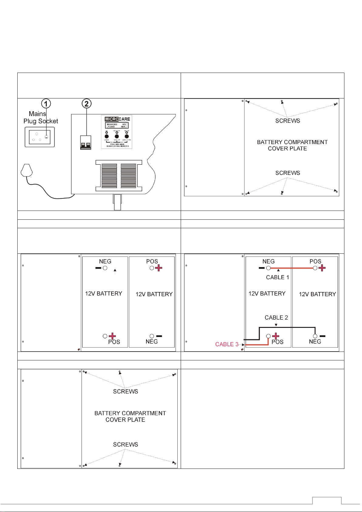
3. UPS BATTERY CONNECTION DIAGRAM
Note the UPS cannot operate without batteries.
IF the UPS is shipped without batteries, follow the following steps:
1) Ensure that the UPS is not plugged into the
mains socket. 2) UPS Battery circuit breaker is
turned off
Remove the 6 battery compartment cover plate
screws
Insert the batteries as shown below.
Connect battery inter-connect ”Cable 1”.
Connect battery “Cable 2”
Connect battery “Cable3”
Re-Fit the battery compartment cover screws
8
4. INVERTER OPERATION
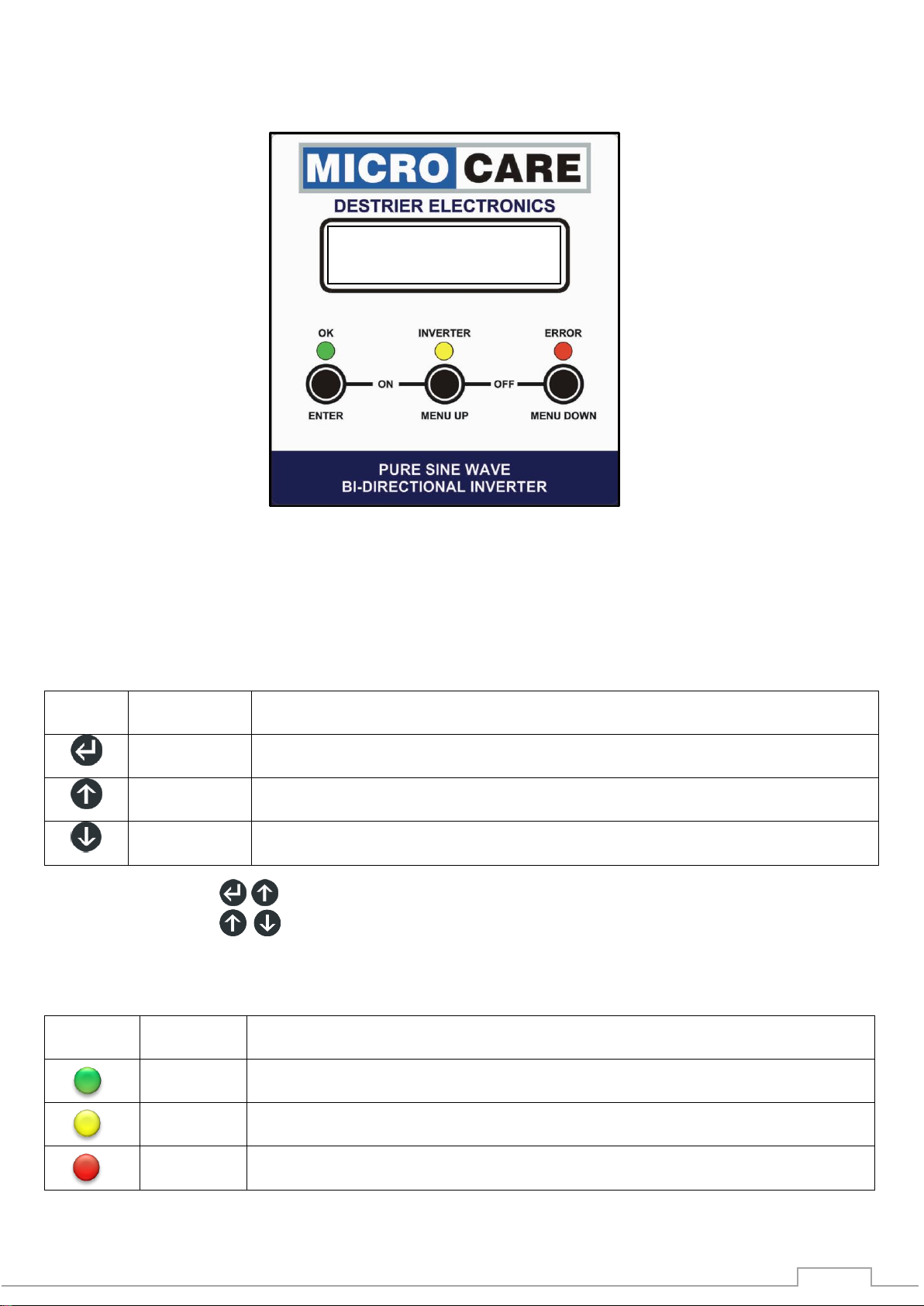
4.1 Front Panel LCD Display/Keypad and Description
Figure 4-1: LCD Display & Keypad
The front Panel Display/Keypad indicates the Inverter’s operational information, including output
voltage, battery voltage, output load, internal temperature and is used for programming.
Panel Display/Keypad operation explained. For ease of explanation the following symbols will be
used to represent the Enter, Menu Up and Menu Down Buttons.
Button Function Description
Symbol
Button
Name
Function description
Enter
Confirms or store DATA, increment or decrement values and to reset
alarm conditions.
Menu Up
Navigates through the list of operational information, parameters and
functions.
Menu Down
Navigates through the list of operational information, parameters and
functions.
Press and hold both for 3 seconds, turns the inverter “ON”.
Press and hold both for 3 seconds, turns the inverter “OFF”
4.2 Inverter Status LED’s
Indicator
Indicator
Name
Description
On
Led on: Indicates the INVERTER is turned on and operating normally
Inverter
Led on: Notification that the Inverter is inverting power from DC Power to
AC Power
Error
Led on: Indicates the INVERTER is in a fault condition because of inverter
shutdown or over temperature
MICROCARE 2KW
UPS ON

9
WARNING!!! LOW
BATTERY CAPACITY
UPS
LOW/HIGH BATTERY
BATTERY CAPACITY
Inverter ON and Grid Supplying the Load
ON
INVERTER
ERROR
Inverter ON and the Battery Supplying the Load “Inverter Mode”
ON
INVERTER
ERROR
Inverter Displaying WARNING “Battery Low Battery Capacity”
ON
INVERTER
ERROR
Steady “ON”, Green , Yellow and Red LED
Buzzer sounds continuously, Press to clear the buzzer and warning
Inverter Warning Switched OFF due to Battery LOW/HIGH Battery Voltage
ON
INVERTER
ERROR
Steady “ON”, Yellow and Red LED
Buzzer sounds continuously
Please Note:
This Inverter is pre-programmed with a set of default values.
These settings might not be correct for your battery type.
Please contact your battery supplier for your battery specifications
“Battery Float Voltage, Boost Voltage, Boost to Float Time “ Absorb Time”
and program the Inverter accordingly

10
4.3 Incorrect Connection
Never connect the UPS mains input plug into UPS output Plug Socket
4.4 Typical Connection Diagram
•Follow the steps in section 4.5 before connecting the UPS to the mains inlet socket and
connecting the loads.

11
MICROCARE 2KW
INVERTER ON
MICROCARE 2KW
INVERTER OFF
MICROCARE 2KW
INVERTER OFF
UPS TURNED OFF
…CALIBRATING…
UPS TURNED OFF
MICROCARE UPS
…PLEASE WAIT…
4.5 Checks Prior To Start-Up
Ensure the following:
•The UPS is standing on its wheels.
•Batteries are installed. “Refer to section 3”
•AC Mains Plug Socket supply to the inverter is switched off (1).
•DC Circuit breaker is turned off (2).
•External Load if connected is switched off.
Figure 4-2
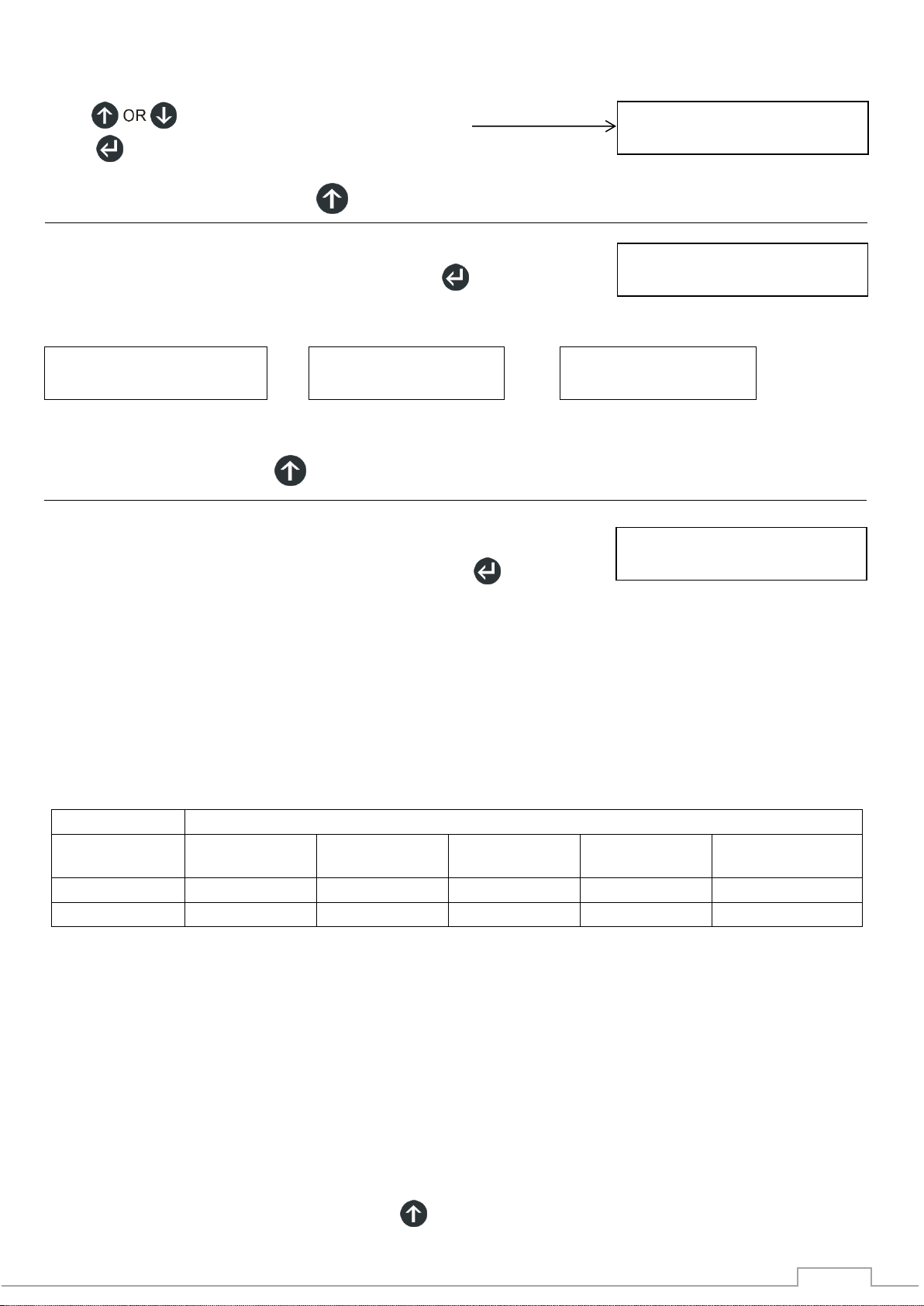
4.6 Start-UP Procedure
If all the conditions in section 4.3 are true, then proceed as follows:
Turn the BATTERY CIRCUIT BREAKER on as labelled in figure 4-2 above..
•The display shows the following:
•The display changes to
•The display changes to
•Press the ENTER Button and the
display will change to:
4.7 Switching the UPS On & Off
Switching the inverter “ON”
Press and hold both and buttons
for up to 3 seconds.
The UPS will start up and the Green LED will light up to
indicate the power is being supplied from the inverter to the load. (Yellow when no mains)
Switching the UPS “OFF”
Press and hold both and buttons
for up to 3 seconds, the UPS will turn OFF after two beeps.

12
BATT VOLTS : 27.2
BATT AMPS : 7.0
UPS VOLTS : 220
UPS AMPS : 7.0
MICROCARE 2KW
INVERTER = 47%
GRID VOLTS : 227
GRID AMPS :10.0
TEMPERATURE
26.3 Deg/Cel
BATT VOLTS : 27.2
CHGR AMPS : 10.0
SIGNAL STRENGTH
DISPLAY- UPS 100%
SN: MCxxx7777
FW: VXXXX
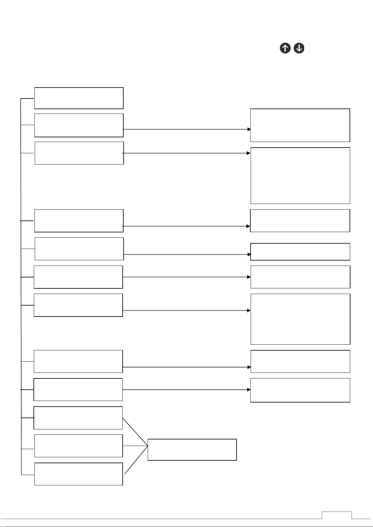
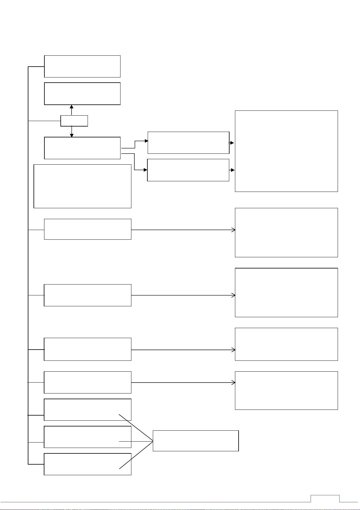
5. INVERTER MENU
In either the inverter ON or OFF mode, use the buttons to view the menu
displays on the LCD screen explained below.
5.1 Power rating of the UPS
The load drawn as a % of the rated power is displayed.
By turning on a load, the OUTPUT % will change to indicate the LOAD
as a %of the unit being used in KW. Above 5% of load is displayed.
This status menu is displayed when the inverter runs from the grid or in inverter mode.
5.2 Battery Volts and Amps
Battery voltage and the amps that the UPS is drawing
from the battery when the inverter runs from the battery.
This status menu is only displayed in inverter mode, the Green and Yellow LED is on.
5.3 Battery Charge Amps and Volts
This shows the Charge Amps that are being put back
into the battery bank from the charging source.
The inverter only charges the batteries when a grid connection is present
This status menu is only displayed when the inverter runs from the grid, the Green LED is on.
5.4 Output Volts and Amps
AC Output voltage and amps that the load is drawing
In inverter mode.
This status menu is displayed when the inverter runs in inverter mode, the Green and Yellow
Led is on.
5.5 Grid Volts and Grid Amps
Grid Volts and power draw from the grid power supply:
This status menu is displayed when running from the grid, the Green LED is on
5.6 Temperature
Internal temperature of the inverter.
5.7 Signal Strength
Control cards in the Inverter have 100% communication.
5.8 Serial Number & Software Version
Serial number of the inverter.
Software version of the inverter.
The Serial number of the inverter needs to be noted and supplied when requesting any fault
support information.

13
ENTER
SETUP MENU?
ENTER
BATTERY MENU?
ENTER
LOG MENU?
EXIT DO NOT SAVE
SETUP MENU?
EXIT AND SAVE
SETUP MENU?
5.9 System Setup
This menu allows the user TO CHANGE the system settings
Sections 10 and 11 Covers the programming of the different parameters.
Set the “Battery Setup Menu” values first and then make changes to the “System Setup Menu”.
5.10 Battery Setup
This menu allows the user TO CHANGE the battery settings
Sections 6 and 7 Covers the programming of the different parameters.
Set the “Battery Setup Menu” values first and then make changes to the “System Setup Menu”.
5.11 Log Menu
5.12 Exit & Save
This menu allows the user TO SAVE all the new setting changes
5.13 Restore Factory Settings
This menu allows the user TO RESTORE the factory
default settings
5.14 Exit Do Not Save
This allows the user NOT TO SAVE any system settings that
were changed.
Sections 6 and 7 Covers the programming of the different parameters.
Set the “Battery Setup Menu” values first and then make
changes to the “System Setup Menu”.
RESTORE FACTORY
SETUP MENU?
14
ENTER
BATTERY MENU ?
BATTERY TYPE
TYPE = LEAD ACID
AC INPUT POWER
LEVEL (X) SELECTED
BATTERY FLOAT
BST = XX.X Volt
BATTERY BST TIME
BST FOR 2 HOURS
BATTERY LOW
OFF AT 44.0
FORCE BAT INTO
AUTO CHARGE
Sets the float voltage
Sets the battery low cut-off
voltage
EXIT AND SAVE
BATTERY MENU?
RESTORE FACTORY
BATTERY MENU?
EXIT DO NOT SAVE
BATTERY MENU?
LAY-UPS
100%
SAVING DATA
PLEASE WAIT
BATTERY BOOST
BST = XX.X Volt
Sets the boost voltage
BATTERY CHARGE
LEVEL (X) SELECTED
6. BATTERY SETUP SETTINGS
6.1 Battery Setup Settings - Quick Reference Guide
Before making any settings changes, switch off the UPS “Press and hold both for 3 seconds,
turns the inverter “OFF”
Menu Settings
Turned off
Slow charge
25% of rated charge
50% of rated charge (Def)
75% of rated charge
Max charge rate
Level 1 (Default)
Level 2,3,4,5,6
Sets the boost time
1 Min, 30 Min
1 Hour
2 Hours (Default)
3 Hours
Auto (Default)
Boost or Float
Sets the battery type
Lead Acid , Lithium 1 or
Lithium 2
15
BATTERY CHARGE
LEVEL (X) SELECTED
ENTER
BATTERY MENU
BATTERY TYPE
TYPE = LEAD ACID
BATTERY TYPE
TYPE = LEAD ACID
BATTERY TYPE
TYPE = LITHIUM 1
BATTERY TYPE
TYPE = LITHIUM 2
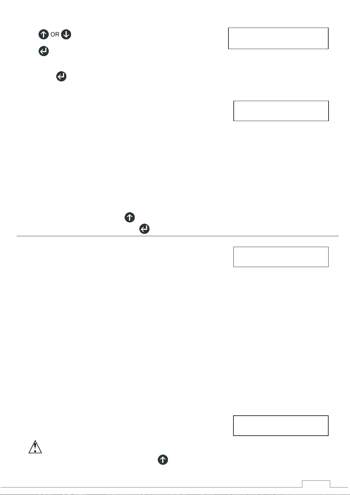
6.2 Battery Setup Procedure
Please consult your battery supplier for the correct battery charging specifications
Press to select BATTERY Set-Up Menu:
Press to access the Battery Setup Menu:
Press , the menu changes to Battery Type
6.3 Battery Type
To change the BATTERY TYPE settings, Press
This allows the user to select the BATTERY TYPE.
OR OR
“Please consult your battery supplier for the correct battery charging specifications”
Press , the menu changes to Battery Charging Rate
6.4 Battery Charging Rate
To change the BATTERY CHARGE settings, Press
:TURNED OFF - 0% of charge rate as per the list supplied below.
SLOW CHARGE - 5% of charge rate as per the list supplied below.
25% OF RATED CHR - 25% of charge rate as per the list supplied below.
50% OF RATED CHR - 50% of charge rate as per list supplied below. (Default)
75% OF RATED CHR - 75% of charge rate as per the list supplied below
.MAX CHARGE RATE - 100% of charge rate as per the list supplied below.
Below is the list of available charge amps for the inverters.
Table 6-1: Battery Setup - Battery Charging rates
INVERTER
Charging Rate (A)
Model
5%
25%
50% -
Default
75%
100%
1kW24V
1A
5A
10A
15A
20A
2kW24V
2A
10A
20A
30A
40A
Regarding the battery charge level. The level selected will allow the battery charge to the batteries.
•Great care should be taken when charging batteries. Please consult your battery supplier for
the optimum battery charging rate for the batteries you have purchased for your installation.
•Overcharging and undercharging can reduce the life of the batteries.
To change the Menu press , the menu changes to AC Input Power

16
AC INPUT
POWER LEVEL (X)
SELECT
ED
BATTERY BOOST
BST = 29.2 V
Circuit Breaker
Inverter
AC Load
Circuit breaker must be placed within 1m from the Inverter
Generator
6.5 AC Input Power From Generator
To change the AC INPUT POWER settings, Press
This allows the inverter to extract the maximum amount of power from a generator.
The inverter constantly monitors the Voltage from the generator and then applies maximum charge.
LEVEL 1 is the highest load to the generator while
LEVEL 6 is the minimum.
The factory default LEVEL is 1.
This setting only needs to be adjusted if there is a generator connected.
When a generator is running the generator will supply the AC Load first and the inverter charges the
batteries with any excess power created from the generator.
Always install a generator with a circuit breaker or contactor connection
Keep the circuit breaker off until the generator is running fully.
Turn of the circuit breaker before switching off the generator.
To change the Menu press , the menu changes to Battery Boost Voltage
6.6 Battery Boost Voltage
To change the BATTERY BOOST settings, Press
This allows the user to adjust the BATTERY BOOST voltage.
The boost settings can be changed as follows
Battery Boost Voltage Settings
Table 6-2a: Battery Setup - Battery Boost Voltage Firmware V10R6
24V System
27.4
Default Lithium 1 & 2
27.6
28
28.1
28.2
28.8
29.2
Default –Lead Acid
30
31
Please Note:
This Inverter is pre-programmed with a set of default values. These settings might not be correct for
your battery type. Please contact your battery supplier for your battery specifications “Battery Float
Voltage, Boost Voltage, Boost to Float Time “ Absorb Time” and program the Inverter accordingly
“Please consult your battery supplier for the correct battery charging specifications”
To change the Menu press , the menu changes to Battery Float Voltage

17
BATTERY BST TIME
BST FOR 2 HOURS
BATTERY LOW
OF AT 22.0 V
BATTERY Float
FLOAT = 27.6 V
6.7 Battery Float Voltage
To change the BATTERY FLOAT VOLTAGE settings, Press
This allows the user to adjust the BATTERY FLOAT voltage.
The float settings can be changed as follows
Battery Float Voltage Settings
Table 6-3B: Battery Setup - Battery Float Voltage Firmware V10R6
24V System
26.8
27
27.2
Default –Lithium 1
27.4
27.6
Default Lead Acid
27.8
28
Default –Lithium 2
“Please consult your battery supplier for the correct battery charging specifications”
To change the Menu press , the menu changes to Battery Boost Time
6.8 Battery Boost Time
To change the BATTERY BOOST TIME settings, Press
This allows the user to select the TIME duration that the BOOST VOLTAGE will be held at before
changing to FLOAT.
By Pressing you can select 1 min, 30min, 1, 2 or 3 hours.
“Please consult your battery supplier for the correct battery charging specifications”
To change the Menu press , the menu changes to Battery Low Off At
6.9 Battery Low Voltage Shut Down
To change the BATTERY LOW OFF AT settings, Press
This selects at which BATTERY LOW VOLTAGE the inverter will shut down
“Also known as: low battery cut-out voltage”
This function prevents the inverter from draining the batteries completely.
When the DC voltage drops below a specified level, the inverter will stop functioning.
The system display will give a Low Battery Voltage message or Low Battery Voltage error.
This function is intended to protect both the batteries and the inverter’s output.
This voltage is adjustable as below.
By Pressing ENTER you can select to change the Battery Low OFF At voltage.
Table 6-4A: Battery Setup: Table 6-4B; Battery Setup
Lead Acid Battery Low Voltage Shutdown Lithium Ion Battery Low Voltage Shutdown
24V System
48V System
20
23.4
21
23.8
22
Default Lead Acid
24.2
23
24.6
Default –Lithium 1 & 2
24
25
25.5
25.4
To change the Menu press , the menu changes to Force Bat Into

18
FORCE BAT INTO
AUTO CHARGE
EXIT AND SAVE
SETUP MENU?
LAY-UPS
100%
RESTORE FACTORY
SETUP MENU?
EXIT , DO NOT SAVE
SETUP MENU?
LAY-UPS
100%
SAVING DATA
PLEASE WAIT
6.10 Force Charge
To change the FORCAE BAT INTO settings, Press
It is possible to FORCE the charger to go into another charge mode on a temporary basis.
If the charger is in FLOAT but you require it to go back into BOOST then the next menu will allow
this. Pressing allows the charge to be changed from, AUTO to BOOST or FLOAT.
Pressing will give you 3 options to SAVE the changed data.
This will give you the options of saving the changes that have been made. Press at the correct
SAVE menu.
OR OR
If the changes to the settings need to be saved Press ENTER,
When the enter button is pressed then the inverter will show:
If no entry is made for 1 minute the display will return to the main menu and the back light will turn off
19
ENTER
SETUP MENU
UPS MODE
NORMAL SENSE
SOLAR CONTROL
BATT RUN TO VOLT
SOLAR CONTROL
AC RUN TO VOLT
TRANSFER SWITCH
8MS + SOFTSTART
LOAD TRANSFER
NO DELAY
IF AC INPUT=ON
AC OUTPUT =NOR
LOAD MONITORING
HIGH NO RESET
EXIT AND SAVE
SETUP MENU?
RESTORE FACTORY
SETUP MENU?
EXIT , DO NOT SAVE
SETUP MENU?
SAVING DATA
PLEASE WAIT
OR
UPS MODE
SOLAR CONTROL
PLEASE NOTE:
If Solar Control Mode is
selected,
Set the charge level to “OFF”
in the battery setup menu.
7. SETUP MENU SETTINGS
7.1 Setup Menu - Quick Reference Guide
Menu Sub-Menu Settings
From the Battery Setup menu
select the battery type first
Lead Acid Battery Run to
Voltage
Lithium Battery Run To Voltage
Lead Acid AC Run To Voltage
Lithium AC run To Voltage
3ms No Soft Start
5ms No Soft Start
8ms + Soft Start (Def)
GEN + Soft Start
GEN + Slow Ramp
High No Reset (Default)
Med No Reset
High 3x Reset
Med 3x Reset
Low Emergency
AC output = NOR (Default)
AC output= 200%
DO NOT SELECT 200%
No Delay (Default)
Delay = 30 sec
Delay = 5 mi
20
ENTER
SETUP MENU ?
UPS MODE
NORMAL SENSE
UPS MODE
SOLAR CONTROL
BATTERY CHARGE
LEVEL (X) 0%
7.2 Setup Menu Settings
Press until the ENTER SETUP MENU appears
Press to enter the SETUP menu.
To menu changes to Normal Sense
By Pressing you can select whether the inverter runs in NORMAL SENSE or SOLAR CONTROL
mode
7.3 Normal Sense - Set the UPS for Normal Sense
When to select Normal Sense?
UPS application –“The load is connected to the Grid most of the time”
•The grid “ESKOM” is the primary energy source and the system switches
to inverter mode when disconnected from the grid eg: “load shedding”.
•As soon the Grid is restored, the load re-connects to the GRID.
•The batteries will only charge when the Grid is present.
OR
Off-Grid application –“No Grid connection is available”
•The battery bank is the primary energy source and the inverter “IS NOT” connected to the grid.
•Renewable energy is used to charge the batteries.
•A generator can be connected to supply the system when needed.
If normal sense is required, press , the menu changes to Transfer Switch Time, section 7.7
If Solar Control Mode is required press , the menu changes to Solar Control Mode
7.4 Solar Control Mode
SOLAR CONTROL MODE EXPLAINED
When to select Solar Control Mode?
•The batteries are the primary energy source and the inverter “IS” connected to the grid.
“Grid assisted solar power system”
•The system uses renewable energy to charge the batteries.
•If the system is correctly sized the inverter will run mostly in inverter mode and will only connect to
the grid when the batteries are discharged to a set level.
•The system will run from the batteries for as long as the batteries can be sustained.
•When the battery voltage reaches the set “ Battery Run To Voltage”, the inverter connects the
load to the grid.
•When the battery reaches the set “AC Run To” voltage, the inverter transfers back to inverter
mode.
•The inverter charger should be switched off in order for the battery bank to be effectively charged
from the renewable energy source.
For Solar Control Mode the following setting must also be changed from the battery setup
menu:
Refer to section 6.1 Charging Rate
Battery Charging Rate
TURNED OFF - 0% of charge rate
Please note: Do not connect a generator when operating in the solar control mode.
To change the Menu, press , the menu changes to: Batt Run To
Other manuals for 1kW24V
1
This manual suits for next models
1
Table of contents
Other Microcare UPS manuals


Popular UPS manuals by other brands

Powerware
Powerware 9330 Installation & operation manual

Next
Next LOGIX II RT NETPACK 1000VA Installation and user manual

Eaton
Eaton MBP6Ki Installation and user manual

Liebert
Liebert UPStation GXT 2U user manual

Toshiba
Toshiba G9000 SERIES Installation and operation manual

Alpha
Alpha Novus FXM 650 Installation & operation manual


