MicroComm DXL TMM-640 User manual

TMM-640 VoIP Touchscreen Master Module
Document IM-TMM-640-1.2 2010-2013 Harding Instruments - Printed in Canada
INSTALLATION
MicroComm DXL
INSTRUCTIONS
Table of Contents
1. Intent & Scope 3
2. Description 3
3. Ethernet Connection 4
4. Handset Connector (or external push-to-talk switch) 5
5. Power Supply 5
6. Configuring a TMM-640 with the Administrator Software 5
7. Setting the IP Address for the TMM-640 8
8. Using a web browser to configure the TMM-640 9
8.1 Using the MicroComm Setup Wizard 9
8.2 Setting the TMM-640 Operating Parameters 15
9. Using the DXL VOIP Device Manager to Configure Multiple Masters 23


TMM-640 VoIP Touchscreen Master Module
Document IM-TMM-640-1.2 Page 3
1. Intent & Scope
This document describes the installation and setup procedures for the DXL TMM-640 VoIP Touchscreen Master
Module.
2. Description
The TMM-640 is a small des top style intercom master station for use with a touchscreen terminal. It is aVoice
over Internet Protocol (VoIP) device that implements the industry standard Session Initiation Protocol. The TMM-
640 connects to an exchange via the inter-exchange Ethernet networ .
The TMM-640 includes a spea er (c/w volume adjustment) an electret microphone, a push-to-tal (PTT) switch,
and a LED status indicator. A front panel 2.5 mm jac allows a variety of wired headsets to be utilized.
The TMM-640 also provides contacts for an external PTT (foot) switch as well as a privacy handset, and includes a
3.5 mm stereo output jac to provide line-level signaling for external amplified spea ers
The TMM-640 is powered by a wall adapter power supply (normally included with the TMM-640) or through
Power over Ethernet (PoE) if you have a PoE capable networ switch.
The functional operation of the TMM-640 in a DXL system is carried out using the Administrator Software and
the DCC software. Three procedures are required to configure a TMM-640 master station:
1. Configuring an IP Master using the Administrator
2. Use DHCP to set the IP Address of the TMM-640 master station
3. Use a web browser to configure the TMM-640 master station to operate with the MicroComm system.
The following diagram shows the location of the connectors on the TMM-640.

TMM-640 VoIP Touchscreen Master Module
Page 4 Document IM-TMM-640-1.2
TMM-640 Showng Connector Locations
The TMM-640 has two RJ-45 connectors, an RJ-11 connector, a 3.5 mm stereo line-level output, and a 2.5 mm
headset connector.
3. thernet Connection
Two vertically stac ed RJ-45 connectors are used to connect the TMM-640 to a DXL system. The bottom RJ-45
includes both the networ and power connections for the TMM and has the capability to accept power from either
an endspan or midspan device.
RJ
-
45 Pins
Function
1
Tx+
2
Tx
-
3
Rx
-
c
4
48 Vdc
Source
5
48 Vdc Source
6
Rx
-
7
48 Vdc Return
8
48 Vdc Return
Table 1: Lower Ethernet Network & PoE
Headset
Jack
LED
Auxillary
Power
RJ-11
Connector
Network
10/100
PoE 10/100
Handset/
Hookswitch
Line
Output
TMM-640
MicroComm
Status
Default
Switch
Aux. Power
-+
Press to talk
Switch
Goose Neck Microphone
12 " long
3.90"
5.35" 7.07"
2.01"
1.07"
RJ-45
Connectors
Volume Control
3.5 mm Stereo
Jack with Line
Level Output
MicroComm
Volume

TMM-640 VoIP Touchscreen Master Module
Document IM-TMM-640-1.2 Page 5
The second RJ-45 includes only the networ connections and can be used to facilitate connections to another
device.
RJ
-
45 Pins
Function
1
Tx
+
2
Tx
-
3
Rx
+
4
NC
5
NC
6
Rx
-
7
NC
8
NC
Upper Ethernet Network
4. Handset Connector (or external push-to-talk switch)
An RJ-11 connector provides a means for a handset connection if call privacy is desired, but will require an
external cradle with hoo switch. A resistor networ is implemented to facilitate both the hoo switch and PTT
inputs to one physical input.
RJ
-
11
Pins
Function
1
HS Mic +
2
Push to Tal
3
HS Sp +
4
HS Sp
-
5
HS Status
6
HS Mic
-
Handset Connections
The handset hoo switch is connected between HS Status (Pin 5) and HS Mic – (Pin 6).
The external press-to-tal switch is a normally open switch that is connected between Push-to tal (Pin 2) and
Mic – (Pin 6)
5. Power Supply
The TMM supports both PoE and line power inputs.
6. Configuring a TMM-640 with the Administrator Software
The Administrator Software is used to create a configuration where a particular VoIP port must be assigned to
each VoIP TMM-640 master station. The first step in creating a configuration is to create all the Exchanges in the
system. The following DXL Configuration Editor screen allows you to Add Exchanges… to the configuration

TMM-640 VoIP Touchscreen Master Module
Page 6 Document IM-TMM-640-1.2
Clic on the Add Exchanges… button and the Exchange
Pro erties text box with two tabs will pop up. In the
Identification tab you need to type in a Number: for the
exchange, the Name: of the exchange and assign a unique
IP Address: to the exchange.
Once all the exchanges have been created each exchange requires a DCC. After the DCC has been configured,
DCEs, TBEs and PZEs can be added to the exchange as required.

TMM-640 VoIP Touchscreen Master Module
Document IM-TMM-640-1.2 Page 7
Using the pull-down menu and setting the Configure: entry to Hardware in the DXL Configuration Editor and
selecting one of the Exchanges you can now add a DCC to the exchange.
Clic on the Add DCC… button to bring up a DCC Pro erties text box as shown on the
right. Use the chec boxes and pull-down menus to configure the DCC. In this example
you are going to use VoIP master stations so the PCI Card: should be set to VOIP. Once
you select VOIP the CEPT Port entry will be dimmed and cannot be selected. When the
parameters of the DCC have been set clic on the OK button and return to the DXL
Configuration Editor.

TMM-640 VoIP Touchscreen Master Module
Page 8 Document IM-TMM-640-1.2
To add a TMM-640 VoIP master station set the
Configure: entry of the DXL Configuration Editor to
Masters then clic on the Add… button to bring up a
Master Pro erties dialog box. In the Identification tab
you need to assign a Number: to the master station, a
Name: for the master station and use the pull down
menu to select the Ty e: of master station. In this case
we need to specify that it is an TMM IP Master.
You must specify the Exchange: associated with this master and assign a unique port number for the IP Master
using the Port pull-down menu. By default the next available port will be displayed.
7. Setting the IP Address for the TMM-640
Every device connected to the inter-networ Ethernet networ in a DXL system must have a unique IP address.
Since the TMM-640 does not have any switches or eypad on it to set its address, it has to initially be given a
temporary address from your networ by using a DHCP (Dynamic Host Configuration Protocol) server. In order
to configure the masters you will need a computer or device (such as a router) that can assign DHCP addresses.
This is used for initial configuration only. After the masters have been configured, they will use Static IP
addresses, and DHCP will no longer be required.
After you have set up a computer or device which acts as a DHCP server, connect up the bottom Ethernet port of
the TMM-640 to the networ switch that the DHCP server is connected to. The networ switch should assign an
IP address to the TMM-640. Once the TMM-640 indicator LED on the front is blin ing green (indicating it is on),
press the PTT switch on the TMM-640. Using a voice synthesizer, the TMM-640 should spea the IP address that
was assigned to it by the DHCP server. Write this address down for use in the next step.
If the TMM-640 spea s a 12 digit Ethernet MAC address this means that the TMM has not received a DHCP
address, indicating that there is probably no DHCP server on the networ
The small opening in the front above the C in MicroComm can be used to activate a switch that will reset the
TMM to the original factory set default values with the address set by the DHCP. The switch must be pressed at
the same time the Ethernet cable is plugged into the TMM.

TMM-640 VoIP Touchscreen Master Module
Document IM-TMM-640-1.2 Page 9
8. Using a web browser to configure the TMM-640
Once the IP address of the TMM-640 has been determined and connected to an Ethernet networ , a PC on the
same networ can access the TMM-640 and use a web browser to set the remaining parameters necessary to ma e
the TMM-640 wor in a DXL system.
The first step is to hoo up the bottom Ethernet port on the master to a networ switch. Once the master has reset
and the LED on the front is flashing green, you can bring up a web browser from a PC on the same networ (that
is assigned an IP address within the same networ mas as the TMM-640).
In the address bar, type “htt ://<address of master>”. For example, if the master is 10.0.0.56, type
“htt ://10.0.0.56”. This will bring up a MicroComm DXL master setup page.
If this is not the first time that the web browser has been used to configure the TMM-640 after a factory reset, the
TMM-640 will s ip the MicroComm Setup Wizard screens and go directly to the web browser menus. The user
will have to sign in as the administrator (using the password assigned during initial configuration) to ma e
changes to these settings. If this is the first setup after a factory reset then the user will have to enter some
information before being allowed to go directly to the web browser menus. The following section describes the
MicroComm Setup Wizard screens and how to configure them. The section after that describes the settings to
ma e in the web browser menus.
8.1 Using the MicroComm Setup Wizard
If this is the first time that the TMM-640 has been configured with a web browser, the following screen will come
up. If this screen is not shown, then the TMM-640 was li ely previously configured, in which case you can s ip to
the next section.
Clic the “Start Setu Wizard” button to continue.

TMM-640 VoIP Touchscreen Master Module
Page 10 Document IM-TMM-640-1.2
On the first page, assign a Workgrou Key. This ey can be any value you choose, but the same ey should be
entered on every IP master in the MicroComm system. In this example, “microcomm” is used for the Workgrou
Key for this system. Once this is entered, clic “Next” to continue.
Next, enter the Extension Name and Extension Descri tion. Enter a short name describing this master in the
Extension name setting. In this case, “TMM-640” is used. Enter a long description for this master as Extension
Descri tion (or leave it blan ). Clic the “Next” button to continue.

TMM-640 VoIP Touchscreen Master Module
Document IM-TMM-640-1.2 Page 11
Next, enter the Extension Number for this TMM-640. This extension number must correspond to the IP master
number configured in the DXL Administrator for this master. There can be only one IP master in the system that
has this extension number. In this example, “6400” was used as the ID number of the master in the DXL
Administrator, so this must be entered as the Extension Number of this TMM-640. Clic the “Next” button to
continue once this has been entered.
Set the DCC/Registrar IP Address to the IP address of the DCC that controls the exchange that the master
associated with in the DXL Administrator. For example, in this case the IP address of the DCC of the exchange
that the Master is associated with is “10.0.0.82”. Once this is entered, clic “Next”.
TMM-640 VoIP Touchscreen Master Module
Page 12 Document IM-TMM-640-1.2
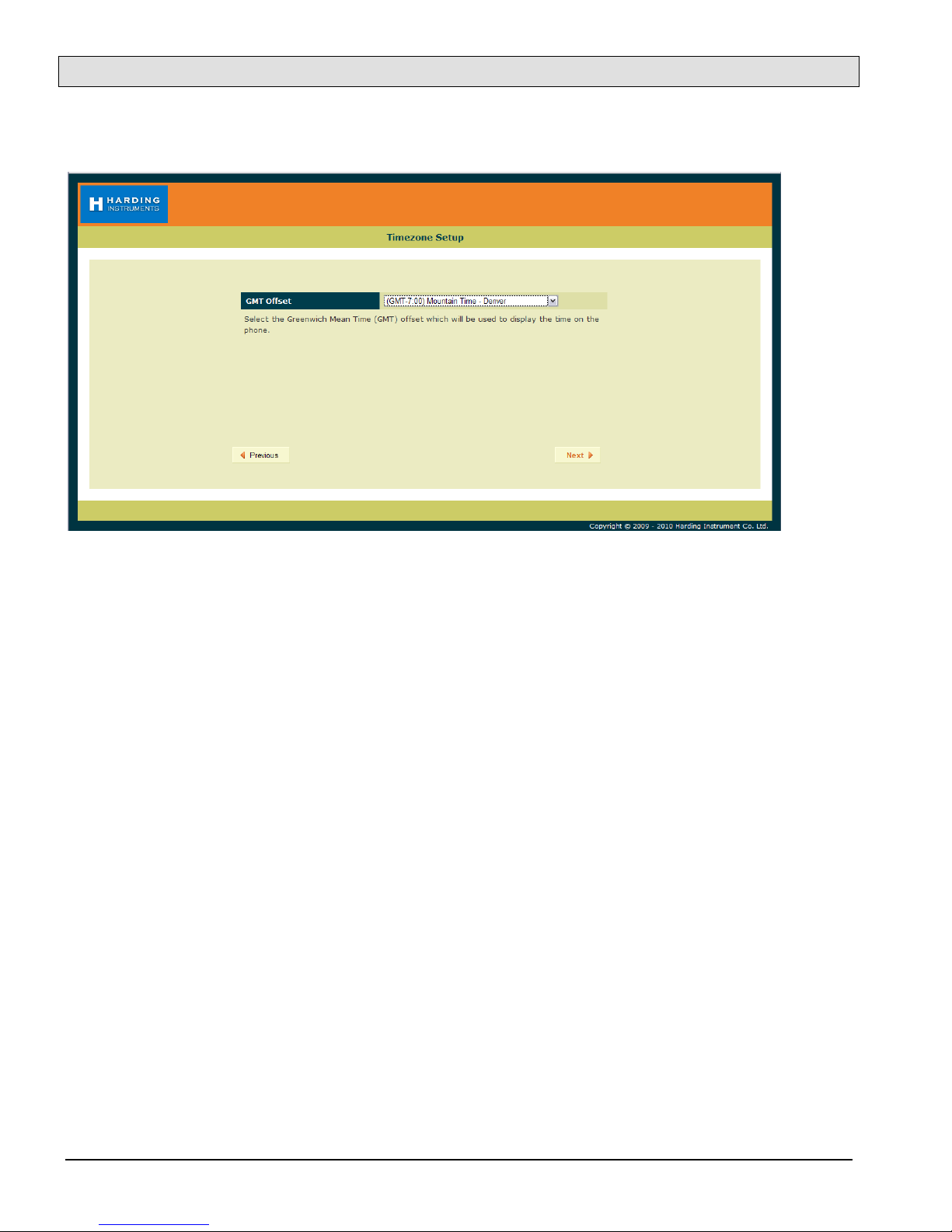
Now set the GMT Offset time zone setting to an appropriate time zone where the master will be used, then clic
“Next”.

TMM-640 VoIP Touchscreen Master Module
Document IM-TMM-640-1.2 Page 13
Next, enter a User Password for the user account on the TMM, then clic “Next”. This allows a separate account
for install or maintenance technicians to examine the TMM-640 parameters, yet while not being able to modify
them. Clic “Next” after the password is entered.
In the following screen, re-type the same User Password to verify it, and then clic “Next”.
TMM-640 VoIP Touchscreen Master Module
Page 14 Document IM-TMM-640-1.2
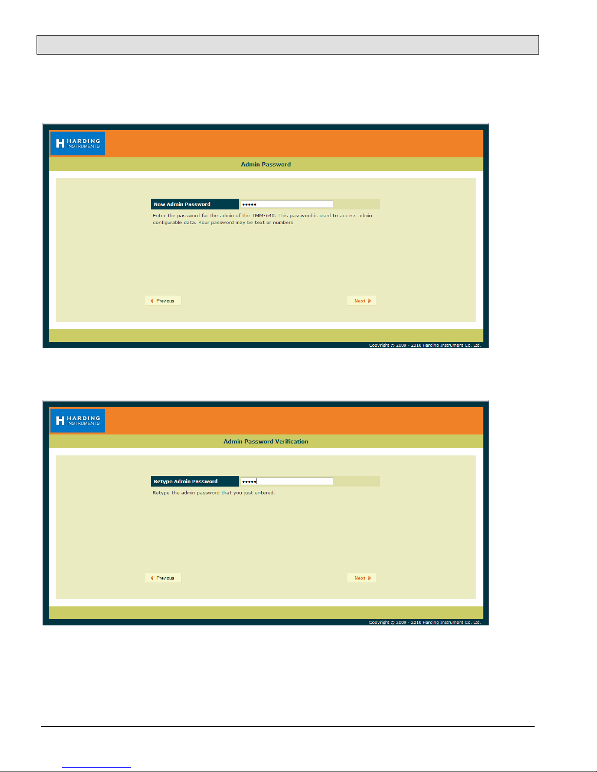
Now enter an Admin Password for the administrator account on the TMM-640, then clic “Next”. The
Administrator account and password will be used to change as well as examine settings. In this case the password
“admin” is used (this will be used later on in the configuration settings).
In the following screen, re-type the same Admin Password to verify it, and then clic “Next”.

TMM-640 VoIP Touchscreen Master Module
Document IM-TMM-640-1.2 Page 15
The next screen shows a summary of the initial settings entered in the MicroComm Setup Wizard. Clic “Next” to
continue.
The last screen in the MicroComm Setup Wizard as s you to confirm the settings you entered. Clic the “U date”
button to complete the wizard.
After this, the main configuration screens will be shown as in the next section.
8.2 Setting the TMM-640 Operating Parameters
If the TMM-640 has been configured with the MicroComm Setup Wizard previously, it will s ip the previous
screens and go directly to the following screen when the web browser accesses the TMM-640’s web page. To ma e

TMM-640 VoIP Touchscreen Master Module
Page 16 Document IM-TMM-640-1.2
changes, the user will have to sign as the administrator using the password previously assigned during the initial
configuration.
The initial web page for configuring the TMM-640 is as follows.
Clic on the “Administrator” text at the top right corner of this page. This will bring up a login prompt text box.
Use the user name “admin” and enter the password assigned to this master (“admin” was assigned in the above
example), then clic OK.
Once you are logged in you will see more menu options.

TMM-640 VoIP Touchscreen Master Module
Document IM-TMM-640-1.2 Page 17
Clic on the Network Address menu tab on the menu bar to bring up the Network Settings menu.
In the Network Settings menu, set the following parameters:
Set Mode to “static” (to assign the master a static IP address). Static is recommended for all IP master stations.
Set IP Address to the IP address for this master. It should be assigned by your networ administrator, and must
not conflict with other IP addresses on this system. In this case this master was assigned address “192.268.0.102”
Set IP Network Mask to the Networ mas for the networ . This is also assigned by your networ administrator,
and should be the same networ mas used for all DXL equipment including IP masters, IP stations, and IP page
spea ers, as well as the DXL DCC’s. This example networ is assigned “255.255.255.0” for the networ mas .
The Gateway, Domain, and DNS Servers settings are typically used if your DXL system extends across one
networ . They are typically left blan , but you can assign the Gateway setting to your gateway server IP address
for this networ , the Domain setting to the domain name of your networ , and the DNS Servers setting to the
DNS server IP address for this networ .
Once you have entered all of the settings you require, clic the “U date” button.
Note that changing the Networ Settings will require a reboot for the settings to ta e effect. In this case you will
get an additional screen outlining the reboot options. You can either use the “Reboot Now” option and re-
establish the connection at the new IP address by typing
“htt ://<address of master>”, in your web browser, or use the “Reboot Later” option and continue to change the
settings and reboot after you have changed all of the settings.

TMM-640 VoIP Touchscreen Master Module
Page 18 Document IM-TMM-640-1.2
Once you have rebooted and logged in, or have continued from the previous screen, select the “Extensions” menu
bar option.
Clic on the number under Extension (which is the extension number entered in the MicroComm Setup Wizard)
to bring up the Settings screen. In this example, the extension number to clic is “x6400”.
The settings for Extensions were previously entered in the MicroComm Setup Wizard, but a brief description of
the settings is below if you need to change them after the initial setup.
Name is a short descriptive name of this master station; in this case “Eng Lab Debugger” is used.
Number is the master number for this master (this must be the same number as the Master Number entered in
the DXL Administrator software for the master station). This master number cannot be the same number as any
other master or IP station in the system. In this case the master number is “6400”.
Comment is an optional long description of this master station, and can be left blan if desired.
If you have changed any settings, clic “U date”.

TMM-640 VoIP Touchscreen Master Module
Document IM-TMM-640-1.2 Page 19
Next, clic on the VoIP Accounts tab on the menu bar.
On the VoIP Account Settings screen, clic the name of the master under VoIP Accounts (in this example, the
name given during setup was “Eng Lab Debugger” so in this case you would clic the text “Eng Lab
Debugger”). This brings up the VoIP Account Settings screen for this master.
These VoIP Account Settings were previously entered in the MicroComm Setup Wizard, but a brief description
of the settings is below if you need to change them after the initial setup.
Account Name is a short description for this SIP account; usually this should be the same as the Extension Name.
Account Username must be the master number (same as the Master Number in the DXL Administrator).
Domain must be set to the IP address of the DCC that controls the exchange that the master associated with in the
DXL Administrator.
Authorization Username, Authorization Password, and Outbound Proxy settings are only used when the TMM-
640 is used with a SIP Proxy server. This is not used for a DXL system, so should be set to blan .
Chec -mar the “Registration Enabled” (or “Register” for older TMM-640s) and “Auto Answer” chec boxes.
The remainder of the settings should be left at the default settings.
If you have made any changes, clic “U date”.

TMM-640 VoIP Touchscreen Master Module
Page 20 Document IM-TMM-640-1.2
Next, clic on the System tab on the menu bar.
Most of these System Settings were previously entered in the MicroComm Setup Wizard, but a brief description
of the settings is below if you need to change them after the initial setup.
Time Server (NTP) is the IP address or Domain Name of a Networ Time Protocol (NTP) server. This can be used
by the TMM-640 master to set its cloc time to same time as the NTP server. This should be left blan for most
cases.
GMT Offset (hours) should be set to the time zone that the TMM-640 will be used in.
Workgrou Key should be set to the wor group name used by all of the IP masters in the MicroComm system.
While the Workgrou Key setting for the networ can be any value you choose, all IP masters should have the
same Workgrou Key.
If you have made any changes, clic “U date”.
Popular Control Unit manuals by other brands

RCS AUDIO-SYSTEMS
RCS AUDIO-SYSTEMS DMM-618A operating instructions

Nibe
Nibe VVM 320 Installer manual

Lutz-Jesco
Lutz-Jesco C 7523 operating instructions

LONG-JOIN
LONG-JOIN JL-205 Series Installation

SpinCore Technologies
SpinCore Technologies PulseBlasterESR-PRO-200-cPCI owner's manual

Toro
Toro 102-2012 installation guide


