Microdyne 20-1100 Series User manual
-
'Instruction Booklet
MODEL 20-1100 SERIES
PREDETECTION UP CONVERTERS
July 1974
TRADE SECRETS
The information contained in/on this document constitutes trade
secrets of Microdyne Corporation and, therefore, the user of this infor
mation covenants and agrees that he/it will not, nor will he/it cause
others io copy or reproduce said information, either in whole or in
part, or manufacture, produce, sell or lease any product copied from or
essentially based upon the information contained herein without prior
written approval of Microdyne Corporation.
J
MICR0DYNE
POST OFFICE BOX 1527 ROCKVILLE, MD. 20850
Telephone (301) 762-8500
Courtesy of http://BlackRadios.terryo.org
20-1100
MODEL 20-1100 SERIES PREDETECTION UP CONVERTERS
*
I
!
r
r
GENERAL
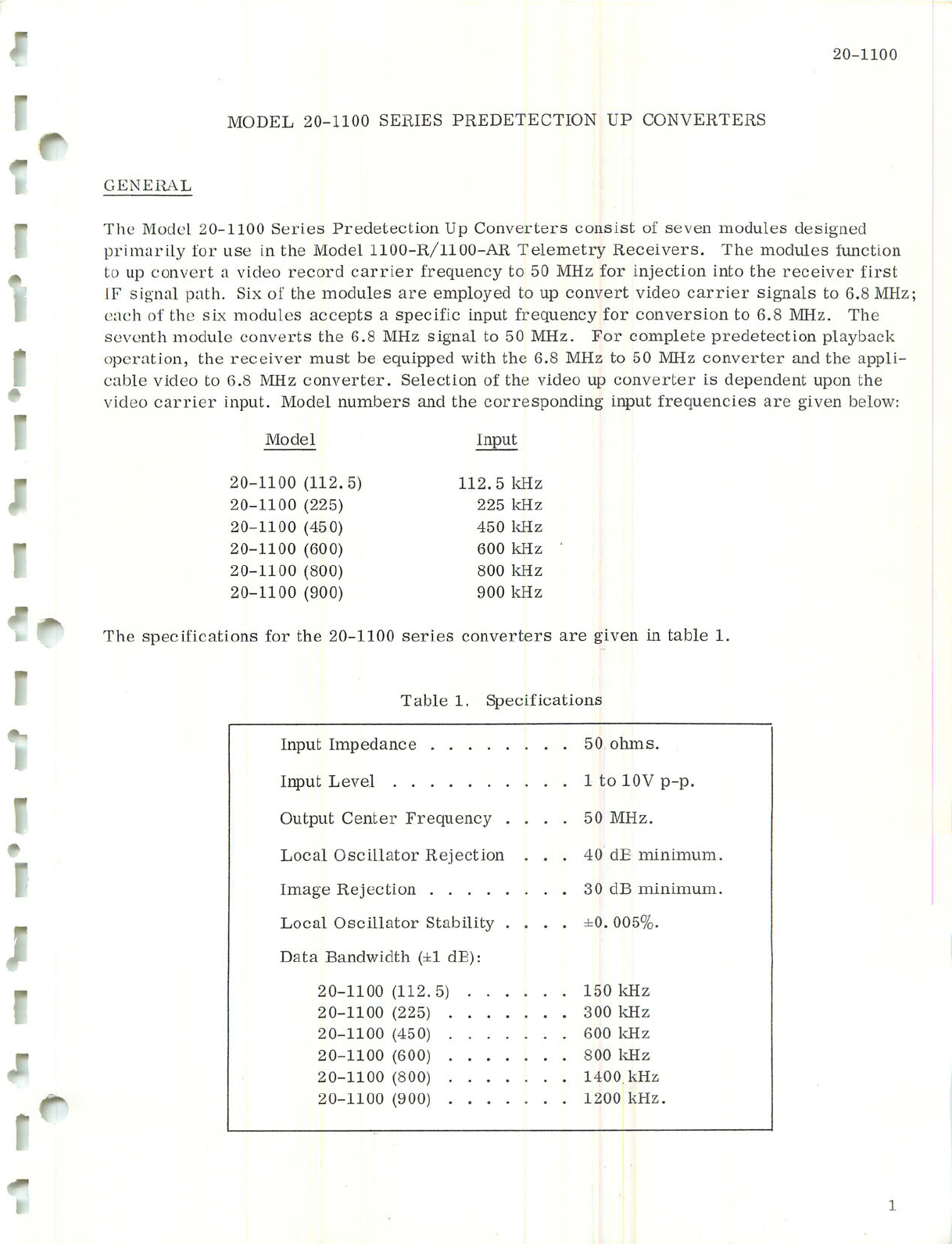
The Model 20-1100 Series Predetection Up Converters consist of seven modules designed
primarily for use in the Model 1100-R/llOO-AR Telemetry Receivers. The modules function
to up convert a video record carrier frequency to 50 MHz for injection into the receiver first
IF signal path. Six of the modules are employed to up convert video carrier signals to 6.8 MHz;
each of the six modules accepts a specific input frequency for conversion to 6.8 MHz. The
seventh module converts the 6.8 MHz signal to 50 MHz. For complete predetection playback
operation, the receiver must be equipped with the 6.8 MHz to 50 MHz converter and the appli
cable video to 6.8 MHz converter. Selection of the video up converter is dependent upon the
video carrier input. Model numbers and the corresponding input frequencies are given below:
Model
20-1100 (112.5)
20-1100 (225)
20-1100 (450)
20-1100 (600)
20-1100 (800)
20-1100 (900)
Input
112.5 kHz
225 kHz
450 kHz
600 kHz
800 kHz
900 kHz
The specifications for the 20-1100 series converters are given in table 1.
Table 1. Specifications
Input Impedance
Input Level
Output Center Frequency .
Local Oscillator Rejection
Image Rejection
Local Oscillator Stability .
Data Bandwidth (±1 dB):
50 ohms.
1 to 10V p-p.
50 MHz.
40 dE minimum.
30 dB minimum.
±0.005%.
20-1100(112.5) 150 kHz
20-1100 (225) 300 kHz
20-1100 (450) 600 kHz
20-1100 (600) 800 kHz
20-1100 (800) 1400 kHz
20-1100 (900) 1200 kHz.
Courtesy of http://BlackRadios.terryo.org
20-1100
INSTALLATION
The units are plugged into parent unit spaces which have been prewired for them and must be
installed in the correct sequence. For example, in the 1100-R series telemetry receivers,
the video to 6. 8 MHz converter must be installed in A18A and the 6.8 MHz to 50 MHz conver
ter must be installed in A18B. The modules are held in place in the receivers by module re
taining clips.
OPERATION
There are no operating procedures applicable to the 20-1100 series converters.
THEORY OF OPERATION
The following description is divided into two parts: that for the video to 6.8 MHz converters,
and that for the 6. 8 to 50 MHz converter. Refer to figures 3 and 4 during the following
discussions.
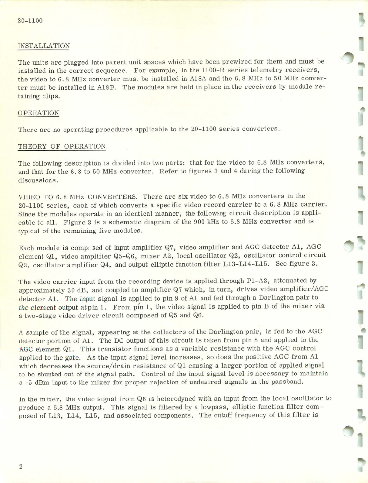
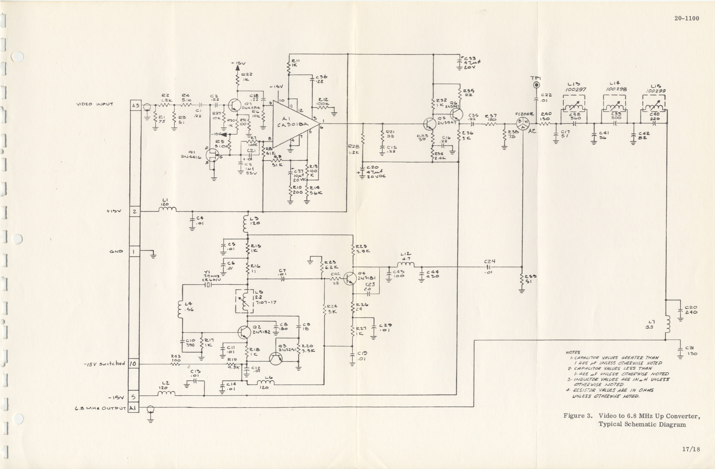
VIDEO TO 6. 8 MHz CONVERTERS. There are six video to 6.8 MHz converters in the
20-1100 series, each of which converts a specific video record carrier to a 6. 8 MHz carrier.
Since the modules operate in an identical manner, the following circuit description is appli
cable to all. Figure 3 is a schematic diagram of the 900 kHz to 6.8 MHz converter and is
typical of the remaining five modules.
Each module is comp; sed of input amplifier Q7, video amplifier and AGC detector Al, AGC
element Ql, video amplifier Q5-Q6, mixer A2, local oscillator Q2, oscillator control circuit
Q3, oscillator amplifier Q4, and output elliptic function filter L13-L14-L15. See figure 3.
The video carrier input from the recording device is applied through P1-A3, attenuated by
approximately 30 dB, and coupled to amplifier Q7 which, in turn, drives video amplifier/AGC
detector Al. The input signal is applied to pin 9 of Al and fed through a Darlington pair to
the element output atpin 1. From pin 1, the video signal is applied to pin B of the mixer via
a two-stage video driver circuit composed of Q5 and Q6.
A sample of the signal, appearing at the collectors of the Darlington pair, is fed to the AGC
detector portion of Al. The DC output of this circuit is taken from pin 8 and applied to the
AGC element Ql. This transistor functions as a variable resistance with the AGC control
applied to the gate. As the input signal level increases, so does the positive AGC from Al
which decreases the source/drain resistance of Ql causing a larger portion of applied signal
to be shunted out of the signal path. Control of the input signal level is necessary to maintain
a -5 dBm input to the mixer for proper rejection of undesired signals in the passband.
In the mixer, the video signal from Q6 is heterodyned with an input from the local oscillator to
produce a 6.8 MHz output. This signal is filtered by a lowpass, elliptic function filter com
posed of LIS, L14, L15, and associated components. The cutoff frequency of this filter is
f
'
$,
Courtesy of http://BlackRadios.terryo.org
'Z pnB i sajnSyj ut UMoqs 9JB sSmsnoq ampoui aqq
UTt{]TA\ pauiBquoo spjBO jmojjo paqujjd am uo squauoduioo jo uot^booj aqx •STuauoduxoo aAyqoajap
.oit]3bjosi ut ptB oq g puB z sajqBq ut papiAOjd ojb sqjBqo aSt^OA 'spoqyara Sujoeaq jbu§ts puB
uoiqoafur jbuSts xbuijou Sutsu paqsTjdraoooB aq Abut syqx 'Pa:)BIosT 8CI PTJioqs arnpoui qBqq ujq:jiA\
a.oBas SuTUOiqounj^BUT aqq 'paunxuajap st ampoui aAiqaajap aqq aouo 'jaqjaAuoo ZHH OS o:l 8*9 JO
jaqjaAuoo oapTA aqq jaqqja 05 pajBiost aq }sjtj pjnoqs uiayqojd aqq 'sanooo uoTqourqiBui b uaqyyA
•SJaqjaAuoa dn sayjas 00XX_02 8in o:l aiqBO]"[ddB aJB sajnpaoojd aouBuaTUTBtu aAjauaAajd o^
j
3DNVN3.1NIVH
•uijp sx~ AjaTBiuyxojddB jo jaAaj b :jb CV"Id
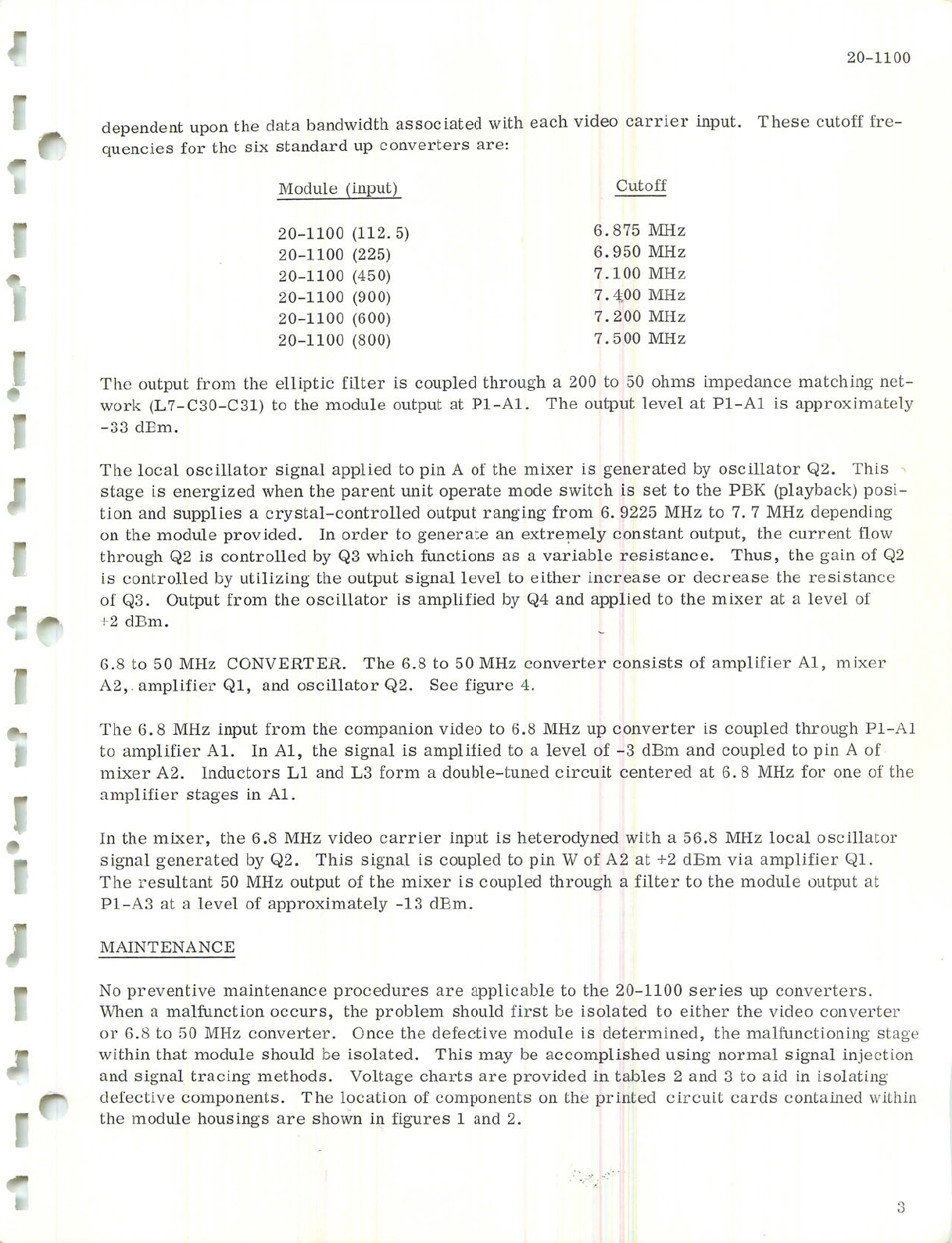
qB qndqno ap-ipoiu aqq oq Jajlji b qSnojqq pajdnoo st jaxjra aqq jo qndqno ZHW OS ?treqmsaa aqx
"XO JanilduiB bta uigp z+ Te ZV 1° A\ uTd oq pajdnoo si reuSjs sjqx '20 &°l poqBJaua.o jbuSts
JoqBniaso reooi zhh 8'9S ^ TO* pauApojaqaq st qndm jaqjjBQ oapjA zjjIAI 8"9 9lll 'JaxTui aqq uj
"XV UT saBBqs jatrridure
aq: jo auo joj zhh 8 '9 ^ pajaquao qmajio paunq-aqqnop b uijoj gq; puB XT SJoqonpuj 'ZV Jaxtui
jo v urd 01 pajdnoa puB tugp g- jo yaAaj b oq paTjiiduiB st jbuSts aqq 'XV UI 'TV JaiJTlduiB oq
TV~Td qSnojqq paydnoo st jaqjaAuoa dn zhh 8"9 oq oapjA uoiuBduioa aqq uiojj qnduy zjxjai 8'9 9qX
■f ajnSrr aag -gO JoqBTjpso pus 'xo J-9T.JTlduiB 'gy
jaxira 'xv JaiJTlduiB jo sqsisuoo jaqjaAuoo zhm OS 05 8'9 9T1X "H"3JLH3ANO0 ZHIAI OS oq 8'9
i•uigp z+
jo pAaj b qB aaxTUi aqq oq paTjddB puB J7O Aq P9TJTlduiB st jomnpso aqq uiojj qndqno 'gO .1°
aoireqstsaj aqq asBaaoap jo asBaJOUT jaqqja oq T_aAaj jbuSts Tndqno aqq SuTZTjim Aq panojqu00 s]
70 jo utb§ aqq 'snqx 'aouB^sisaj ajqBTJBA b sb suotjouuj qoyqAV gO Aq panojqnoo st zb qSnojqq
a\oxj tuajjno aqq 'mdqno quBqsuoo Apuiaj^xa ub aqBJauaS oq japjo uj 'papTAOjd ajnpoui aqq uo
Suipuadap zhw L 'I oq zjiw SSZ6 '9 uiojj SutSubj mdmo panojquoo-yBqsAjo b sanddns puB uoyn
-]Sod (>[oecjABT.d) 513d dVtt °1 l9s st qoq]A\s apoui aqBJado q]un quaJBd aip uaqM pazySjaua si a§Bqs
siqx 'Zb JoqBnjoso Kq paq-BjauaS st jax]ui aqq jo v u!<! o:) pajlddB jbuSts jo^bhtoso ^booj aqx
•raap gg-
AyamuiTxojddB st xv-Td 1^ pAa^ mdmo aqx 'XV-Td V& mdmo ajnpora aqq oq (xgO-OCD-ZT) >IJ0A\
-qau Suyqomui aouBpaduiT suiqo OS oq Q0£ ^ qSnojqq paydnoo st Jaqpj OT^dTjp ^U uiojj mdmo aqx
ZHH OOS'i
ZHH 002 'L
ZHH 00-t'i-
ZHH OOX'A
ZHH 0S6'9
ZHH Si8"9
Jjomo
(008) 0011-02
(009) 00TX-02
(006) 00XT-02
(OSf/) 00TX-02
(S22) 00TI-0S
(STXT) 00TI-02
(mduy) aynpoxM
J
I
I
J
I
-
:ajB sJaqjaAuoo dn pjBpuBas xts aqq Joj sarouanb
-ajj jjomo asaqx -indm J8tjjbo oapjA qoBa qx!A\ payByoossB qmyMpuBq b^bp aqq uodn quapuadap
0011-02
Courtesy of http://BlackRadios.terryo.org
20-1100
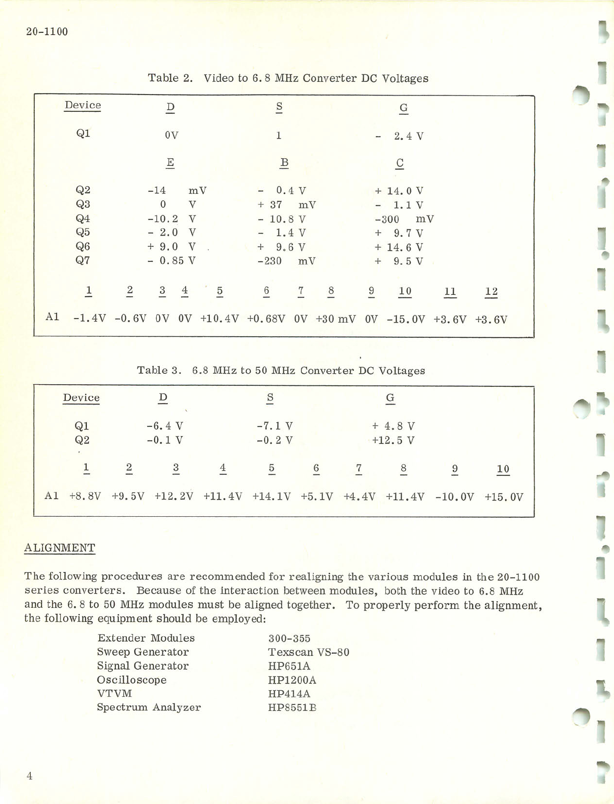
Table 2. Video to 6. 8 MHz Converter DC Voltages
Device D S G
Ql 0V
E
1
B
- 2 . 4 V
C
Q2 -14 mV - 0.4 V + 14. 0 V
Q3 0 V + 3 7 m V - 1.1 V
Q4 -10.2 V- 10.8 V -300 mV
Q5 - 2.0 V- 1.4 V + 9.7 V
Q6 + 9.0 V . + 9.6 V + 14. 6 V
Q7 - 0.85 V -230 mV + 9.5 V
12 3 4 5 6 7 89 1 0 1 1 1 2
Al -1.4V -0.6V 0V 0V +10. 4V +0. 68V 0V +30 mV 0V -15.0V +3.6V +3.6V
T;ible 3. 6.8 MHz to 50 MHz Converter DC Voltages
Device D S G
Ql -6.4 V -7.1 V + 4.8 V
Q2 -0.1 V -0.2 V +12.5 V
1 2 34 5 6 7 8 910
Al +8.8V +9 . 5V +12. 2V +11. 4V +14. IV +5. IV +4.4V +11.4V -10.OV +15.0V
ALIGNMENT
The following procedures are recommended for realigning the various modules in the 20-1100
series converters. Because of the interaction between modules, both the video to 6.8 MHz
and the 6. 8 to 50 MHz modules must be aligned together. To properly perform the alignment,
the following equipment should be employed:
Extender Modules
Sweep Generator
Signal Generator
Oscilloscope
VTVM
Spectrum Analyzer
300-355
Texscan VS-80
HP651A
HP1200A
HP414A
HP8551B
"
1
1
1
1
I.
Courtesy of http://BlackRadios.terryo.org
20-1100
I
OSCILLATOR ADJUSTMENT. The oscillators of both modules are adjusted in an identical
manner. If the oscillator in either module has been repaired, it is only necessary to adjust
that stage. Do not adjust the tuned circuits unless absolutely necessary.
a. Remove the cover and install the module into the receiver
using the extender module.
b. Connect the HP414A to the emitter of the oscillator transistor.
c. Adjust the oscillator coil for a meter null.
d. Disconnect the meter.
TUNED CIRCUIT ADJUSTMENT.
a. Remove the covers and install the modules into the receiver using
the extender modules.
b. Connect the RF output of the VS-80 sweep generator to TPl on the
video converter.
c. Connect the output of the 6.8 to 50 MHz converter to the VIDEO IN
connector of the VS-80.
d. Connect the vertical and horizontal outputs of the VS-80 to the cor
responding inputs of the oscilloscope.
r
e. Set the VS-80 for a 6. 8 MHz output.
f. Adjust the VS-80 output level and the oscilloscope controls for a
convenient display.
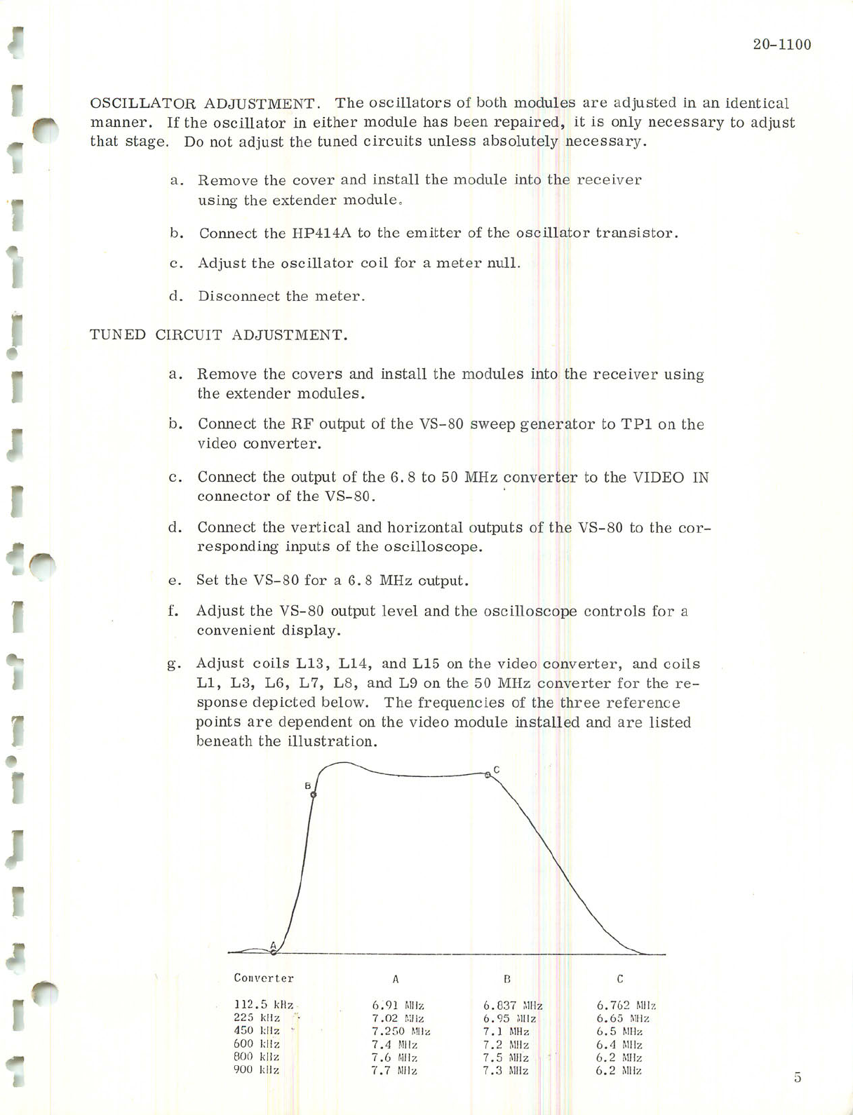
g. Adjust coils L13, L14, and L15 on the video converter, and coils
Ll, L3, L6, L7, L8, and L9 on the 50 MHz converter for the re
sponse depicted below. The frequencies of the three reference
points are dependent on the video module installed and are listed
beneath the illustration.
Com'erter
112 5 kHz
225 kHz
450 1; Iz '
600 1c Iz
800 kiz
900 1: lz
6.91 MHz
7.02 KHz
7.250 MHz
1.4 MHz
7.6 MHz
7.7 MHz
B
6.837 MHz
6.95 MHz
7.1 MHz
7.2 MHz
7.5 MHz
7.3 MHz
6.762 MHz
6.65 MHz
6.5 MHz
6.4 MHz
6.2 MHz
6.2 MHz
Courtesy of http://BlackRadios.terryo.org

20-1100
h. Disconnect the sweep generator and oscilloscope.
i. Connect the output of the HP651A to the input of the video converter.
This connection can be made using the receiver rear apron video input.
j. Connect the input of the spectrum analyzer to the output of the 50 MHz
converter.
k. Set the HP651A for an output frequency corresponding to the low end
frequency of the data bandwidth. For example, the 20.1100 (900) data
bandwidth is 1200 kHz or ±600 kHz on either side of the 900 kHz center
frequency. Subtracting 600 kHz from 900 kHz, the low end frequency
is 300 kHz. Set the output level of the HP651A to 2V RMS.
1. Note the amplitude of the main signal compared to the amplitude of the
adjacent responses. The spurious response should be at least 35 dB
below the main signal amplitude.
m. Vary the frequency of the HP651A over the data bandwidth and note that
all spurious responses remain 35 dB down.
n. Reset the generator to the low end frequency.
o. Vary the input level from 0. 35V RMS to 3.1 RMS, and note that the
main signal spike varies less than 2 dB.
p. Disconnect all test equipment and replace the cover.
REPLACEMENT PARTS LIST
Reference
Designation
i
\
~
6.8 - 50MHz CONVERTER
Description
Al Integrated Circuit, RCA CA3018A
A2 Mixer, Lorch FC-200R
CI Capacitor, ceramic, 0.01^F±20%, 100V, Erie 8121-100-X5V-103M
C2 Capacitor, ceramic, 0. 01 fxF ±20%, 100V, Erie 8121-100-X5V-103M
C3 Capacitor, ceramic, 56 pF ±5%, 100V, Erie 8131-100-COG-560J
C4
thru Capacitor, ceramic, 0. 01 jitF ±20%, ,100V, Erie 8121-100-X5V-103M
C6 -
C7 Capacitor, ceramic, 39 pF ±5%, 100V, Erie 8121-100-COG-390J
C8 Capacitor, ceramic, 0.01uF±20%, 100V, Erie 8121-100-X5V-103M
C9 Capacitor, ceramic, 47 pF ±5%, 100V, Erie 8131-100-COG-470J
C10 Capacitor, ceramic, 47 pF ±5%, 100V, Erie 8131-100-COG-470J
Cll Capacitor, ceramic, 0. 01 /xF ±20%, 100V, Erie 8121-100-X5V-103M
C12 Capacitor, ceramic, 110 pF ±5%, 100V, Erie 8121-100-COG-lllJ
C13 Capacitor, ceramic, 33 pF ±5%, 100V, Erie 8121-100-COG-330J
Courtesy of http://BlackRadios.terryo.org
r
I
■r
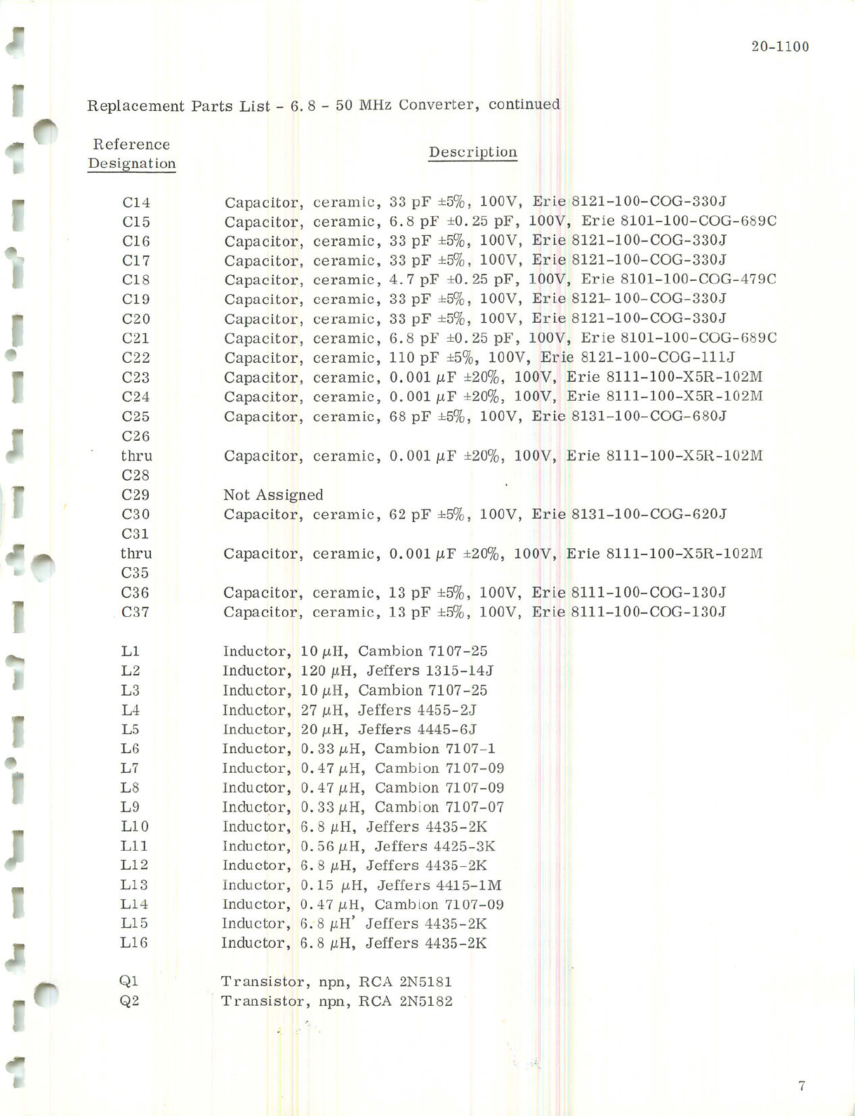
Replacement Parts List - 6. 8 - 50 MHz Converter, continued
20-1100
Reference
Designation
C14
C15
C16
C17
C18
C19
C20
C21
C22
C23
C24
C25
C26
thru
C28
C29
C30
C31
thru
C35
C36
C37
Ll
L2
L3
L4
L5
L6
L7
L8
L9
L10
Lll
L12
L13
L14
L15
L16
Ql
Q2
Description
Capacitor, ceramic, 33pF±5%, 100V, Erie 8121-100-COG-330J
Capacitor, ceramic, 6. 8 pF ±0. 25 pF, 100V, Erie 8101-100-COG-689C
Capacitor, ceramic, 33 pF ±5%, 100V, Erie 8121-100-COG-330J
Capacitor, ceramic, 33 pF ±5%, 100V, Erie 8121-100-COG-330J
Capacitor, ceramic, 4.7 pF ±0.25 pF, 100V, Erie 8101-100-COG-479C
Capacitor, ceramic, 33 pF ±5%, 100V, Erie 8121-100-COG-330J
Capacitor, ceramic, 33 pF ±5%, 100V, Erie 8121-100-COG-330J
Capacitor, ceramic, 6. 8 pF ±0. 25 pF, 100V, Erie 8101-100-COG-689C
Capacitor, ceramic, 110 pF ±5%, 100V, Erie 8121-100-COG-lllJ
Capacitor, ceramic, 0. 001 \xF ±20%, 100V, Erie 8111-100-X5R-102M
Capacitor, ceramic, 0. 001 \xF ±20%, 100V, Erie 8111-100-X5R-102M
Capacitor, ceramic, 68 pF ±5%, 100V, Erie 8131-100-COG-680J
Capacitor, ceramic, 0. 001 juF ±20%, 100V, Erie 8111-100-X5R-102M
Not Assigned
Capacitor, ceramic, 62 pF ±5%, 100V, Erie 8131-100-COG-620J
Capacitor, ceramic, 0. 001 jiF ±20%, 100V, Erie 8111-100-X5R-102M
Capacitor, ceramic, 13 pF ±5%, 100V, Erie 8111-100-COG-130J
Capacitor, ceramic, 13 pF ±5%, 100V, Erie 8111-100-COG-130J
Inductor
Inductor
Inductor
Inductor
Inductor
Inductor
Inductor
Inductor
Inductor
Inductor
Inductor
Inductor
Inductor
Inductor
Inductor
Inductor
IOjuH, Cambion 7107-25
120 /iH, Jeffers 1315-14J
10 juH, Cambion 7107-25
27 juH, Jeffers 4455-2J
20 /iH, Jeffers 4445-6J
0.33/xH, Cambion 7107-1
0.47 /iH, Cambion 7107-09
0.47juH, Cambion 7107-09
0. 33 /LtH, Cambion 7107-07
6.8 /iH, Jeffers 4435-2K
0. 56 uH, Jeffers 4425-3K
6.8 MH, Jeffers 4435-2K
0.15 /iH, Jeffers 4415-1M
0.47 /iH, Cambion 7107-09
6.8/iH' Jeffers 4435-2K
6.8 mH, Jeffers 4435-2K
Transistor, npn, RCA 2N5181
Transistor, npn, RCA 2N5182
Courtesy of http://BlackRadios.terryo.org

20-1100
Replacement Parts List - 6.8 - 50 MHz Converter, continued
Reference _ . ,.
Description
Designation
PI
Yl
Connector, Cannon DBM-13W3P
RI Resistor, fixed composition,
R2 Resistor, fixed composition,
R3 Resistor, fixed composition,
R4 Resistor, fixed composition,
R5 Resistor, fixed composition,
R6 Resistor, fixed composition,
R7 Resistor, fixed composition,
R8 Resistor, fixed composition,
R9 Resistor, fixed composition,
RIO Resistor, fixed composition,
Ril Resistor, fixed composition,
R12 Resistor, fixed composition,
R13 Resistor, fixed composition,
R14 Not Assigned
R15 Resistor, fixed composition,
R16 Resistor, fixed composition,
R17 Resistor, fixed composition,
R18 Resistor, fixed composition,
R19 Resistor, fixed composition,
R20 Resistor, fixed composition,
R21 Resistor, fixed composition,
R22 Resistor, fixed composition,
R23 Resistor, fixed composition,
R24 Resistor, fixed composition,
5.1Kft ±5%, jw, Allen Bradley CB5125
1. 8Kft ±5%, iw, Allen Bradley CB1825
7. 5Kft ±5%, iw, Allen Bradley CB7525
2.7Kft ±5%, iw, Allen Bradley CB2725
10fl ±5%, iw, Allen Bradley CE1005
510ft ±5%, iw, Allen Bradley CB5115
100ft ±5%, iw, Allen Bradley CB1015
20Kft ±5%, |w, Allen Bradley CB2035
lOKft ±5%, iw, Allen Bradley CB1035
lKft ±5%, iw, Allen Bradley CB1025
lKft ±5%, iw, Allen Bradley CB1025
39ft ±5%, iw, Allen Bradley CB3905
51ft ±5%, iw, Allen Bradley CB5105
lKft ±5%, iw, Allen Bradley CB1025
lift ±5%, iw, Allen Bradley CB1105
6.2Kft ±5%, iw, Allen Bradley CB6225
9. lKft ±5%, iw, Allen Bradley CB9125
330ft ±5%, iw, Allen Bradley CB3315
620ft ±5%, iw, Allen Bradley CB6215
lKft ±5%, iw, Allen Bradley CE1025
lKft ±5%, iw, Allen Bradley CB1025
4.3Kft ±5%, iw, Allen Bradley CB4325
1.2Kft ±5%, iw, Allen Bradley CB1225
Crystal, 56.8 MHz, Piezo CR-76A/U
900 kHz UP CONVERTER
Reference
Designation
Al
A2
CI
C2
C3
C4
thru
Description
Integrated Circuit, RCA CA3018A
Mixer, Lorch FC-200R
Capacitor, ceramic, 0.22/iF±20%, Erie 8133-000-250-224M
Capacitor, ceramic, 0.22/iF±2O%, Erie 8133-000-250-224M
Capacitor, ceramic, 1.0 juF, 35V, Sprague 150D105X9035A2
Capacitor, ceramic, 0.01 uF ±20%, 100V, Erie 8121-100-X5V-103M
C7
Courtesy of http://BlackRadios.terryo.org
20-1100
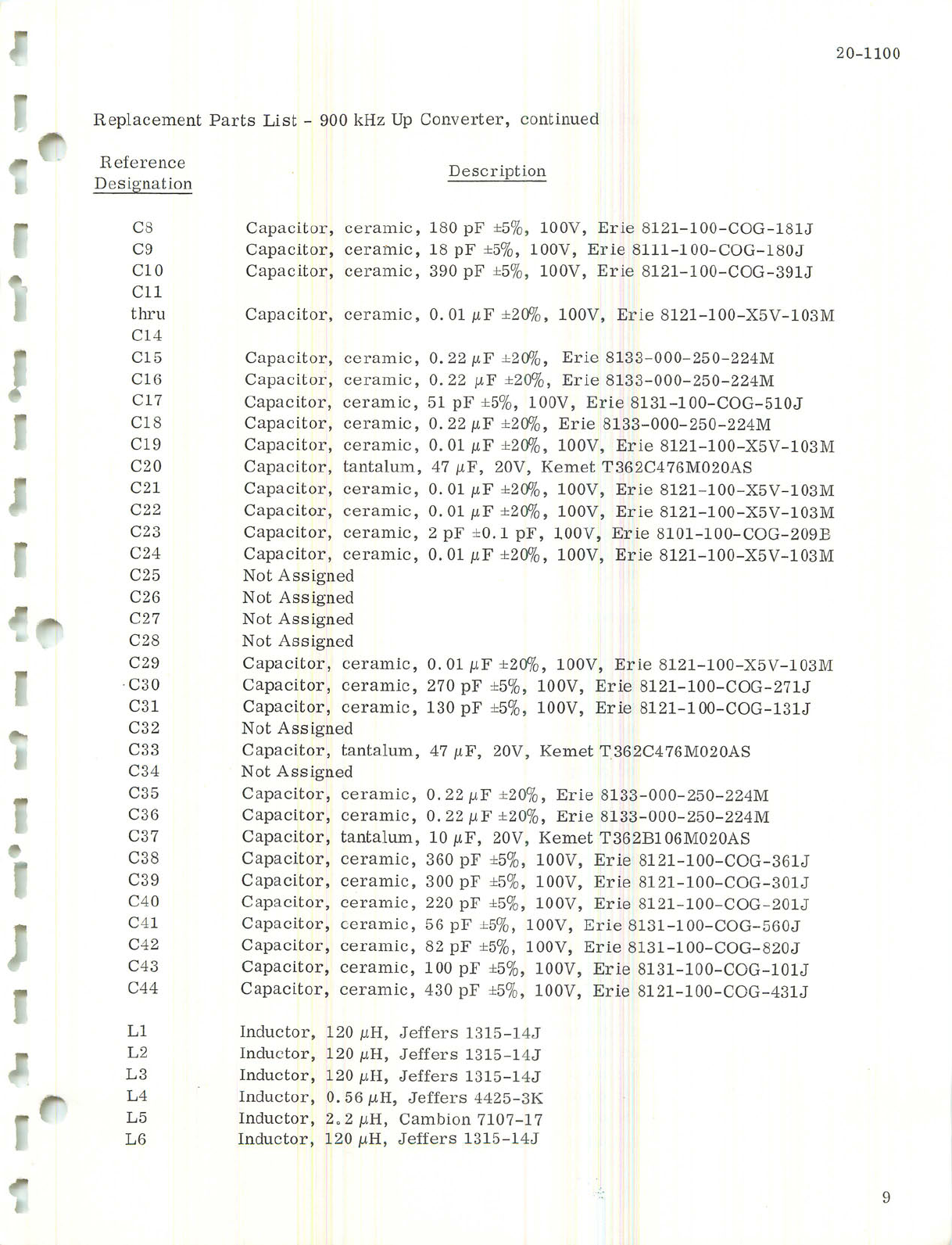
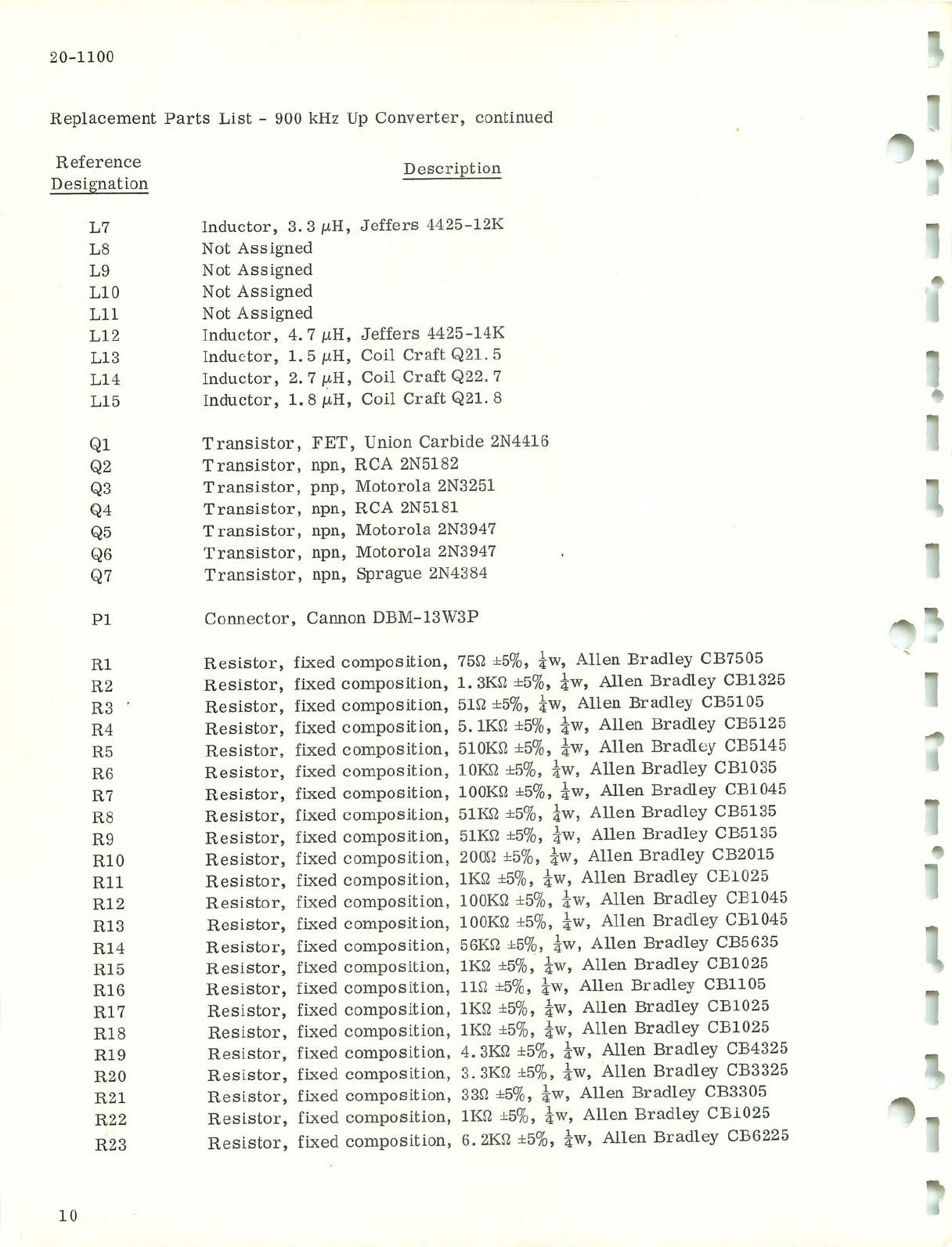
Replacement Parts List - 900 kHz Up Converter, continued
Reference
Designation
C8
C9
CIO
Cll
thru
C14
C15
C16
C17
C18
C19
C20
C21
C22
C23
C24
C25
C26
C27
C28
C29
C30
C31
C32
C33
C34
C35
C36
C37
C38
C39
C40
C41
C42
C43
C44
Ll
L2
L3
L4
L5
L6
Description
Capacitor, ceramic, 180 pF ±5%, 100V, Erie 8121-100-COG-181J
Capacitor, ceramic, 18 pF ±5%, 100V, Erie 8111-100-COG-180J
Capacitor, ceramic, 390 pF ±5%, 100V, Erie 8121-100-COG-391J
Capacitor, ceramic, 0.01/iF ±20%, 100V, Erie 8121-100-X5V-103M
Capacitor, ceramic,
Capacitor, ceramic,
Capacitor, ceramic,
Capacitor, ceramic,
Capacitor, ceramic,
Capacitor, tantalum,
Capacitor, ceramic,
Capacitor, ceramic,
Capacitor, ceramic,
Capacitor, ceramic,
Not Assigned
Not Assigned
Not Assigned
Not Assigned
Capacitor, ceramic,
Capacitor, ceramic,
Capacitor, ceramic,
Not Assigned
Capacitor, tantalum,
Not Assigned
Capacitor, ceramic,
Capacitor, ceramic,
Capacitor, tantalum,
Capacitor, ceramic,
Capacitor, ceramic,
Capacitor, ceramic,
Capacitor, ceramic,
Capacitor, ceramic,
Capacitor, ceramic,
Capacitor, ceramic,
0.22/uF ±20%, Erie 8133-000-250-224M
0.22 /iF ±20%, Erie 8133-000-250-224M
51 pF ±5%, 100V, Erie 8131-100-COG-510J
0.22/iF ±20%, Erie 8133-000-250-224M
0.01/iF ±20%, 100V, Erie 8121-100-X5V-103M
47 /xF, 20V, Kemet T362C476M020AS
0.01/iF ±20%, 100V, Erie 8121-100-X5V-103M
0.01/iF±20%, 100V, Erie 8121-100-X5V-103M
2 pF ±0.1 pF, 100V, Erie 8101-100-COG-209B
0.01/iF ±20%, 100V, Erie 8121-100-X5V-103M
0.01/iF ±20%, 100V, Erie 8121-100-X5V-103M
270 pF ±5%, 100V, Erie 8121-100-COG-271J
130 pF ±5%, 100V, Erie 8121-1 00-COG-131J
47 (UF, 20V, Kemet T362C476M020AS
0.22/iF ±20%, Erie 8133-000-250-224M
0. 22 /xF ±20%, Erie 8133-000-250-224M
10 /iF, 20V, Kemet T362B106M020AS
360 pF ±5%, 100V, Erie 8121-100-COG-361J
300 pF ±5%, 100V, Erie 8121-100-COG-301J
220 pF ±5%, 100V, Erie 8121-100-COG-201J
56pF±5%, 100V, Erie 8131-100-COG-560J
82 pF ±5%, 100V, Erie 8131-100-COG-820J
100 pF ±5%, 100V, Erie 8131-100-COG-lOU
430 pF ±5%, 100V, Erie 8121-100-COG-431J
Inductor, 120 /iH, Jeffers 1315-14J
Inductor, 120 /iH, Jeffers 1315-14J
Inductor, 120 /iH, Jeffers 1315-14J
Inductor, 0.56/iH, Jeffers 4425-3K
Inductor, 2.2/iH, Cambion 7107-17
Inductor, 120 /iH, Jeffers 1315-14J
Courtesy of http://BlackRadios.terryo.org
20-1100
Replacement Parts List - 900 kHz Up Converter, continued
Reference Description
Designation
L7 Inductor, 3.3/iH, Jeffers 4425-12K
L8 Not Assigned
L9 Not Assigned
L10 Not Assigned
Lll Not Assigned
L12 Inductor, 4.7/iH, Jeffers 4425-14K
L13 Inductor, 1.5/iH, Coil Craft Q21. 5
L14 Inductor, 2. 7 /iH, Coil Craft Q22. 7
L15 Inductor, 1. 8 /iH, Coil Craft Q21. 8
Ql Transistor, FET, Union Carbide 2N4416
Q2 Transistor, npn, RCA 2N5182
Q3 Transistor, pnp, Motorola 2N3251
Q4 Transistor, npn, RCA 2N5181
Q5 Transistor, npn, Motorola 2N3947
Q6 Transistor, npn, Motorola 2N3947
Q7 Transistor, npn, Sprague 2N4384
PI Connector, Cannon DBM-13W3P
R4
R5
R6
R7
R8
1
RI Resistor, fixed composition, 75ft ±5%, iw, Allen Bradley CB7505
R2 Resistor, fixed composition, 1.3KB ±5%, iw, Allen Bradley CB1325
R3 Resistor, fixed composition, 51ft ±5%, iw, Allen Bradley CB5105
Resistor, fixed composition, 5.1Kft ±5%, iw, Allen Bradley CB5125 _
Resistor, fixed composition, 510Kft ±5%, iw, Allen Bradley CB5145
Resistor, fixed composition, lOKft ±5%, iw, Allen Bradley CB1035
Resistor, fixed composition, lOOKft ±5%, iw, Allen Bradley CB1045
Resistor, fixed composition, 51Kft ±5%, iw, Allen Bradley CB5135
R9 Resistor, fixed composition, 51Kft ±5%, iw, Allen Bradley CB5135
R10 Resistor, fixed composition, 200ft ±5%, iw, Allen Bradley CB2015
Rll Resistor, fixed composition, lKft ±5%, iw, Allen Bradley CE1025
R12 Resistor, fixed composition, lOOKft ±5%, iw, Allen Bradley CB1045
R13 Resistor, fixed composition, lOOKft ±5%, iw, Allen Bradley CB1045
R14 Resistor, fixed composition, 56Kft ±5%, iw, Allen Bradley CB5635
R15 Resistor, fixed composition, lKft ±5%, iw, Allen Bradley CB1025
R16 Resistor, fixed composition, lift ±5%, iw, Allen Bradley CB1105
R17 Resistor, fixed composition, lKft ±5%, iw, Allen Bradley CB1025
R18 Resistor, fixed composition, lKft ±5%, iw, Allen Bradley CB1025
R19 Resistor, fixed composition, 4.3Kft ±5%, iw, Allen Bradley CB4325
R20 Resistor, fixed composition, 3.3Kft ±5%, iw, Allen Bradley CB3325
R21 Resistor, fixed composition, 33ft ±5%, iw, Allen Bradley CB3305
R22 Resistor, fixed composition, lKft ±5%, iw, Allen Bradley CB1025 1 .
R23 Resistor, fixed composition, 6.2Kft ±5%, iw, Allen Bradley CB6225
10
Courtesy of http://BlackRadios.terryo.org
20-1100
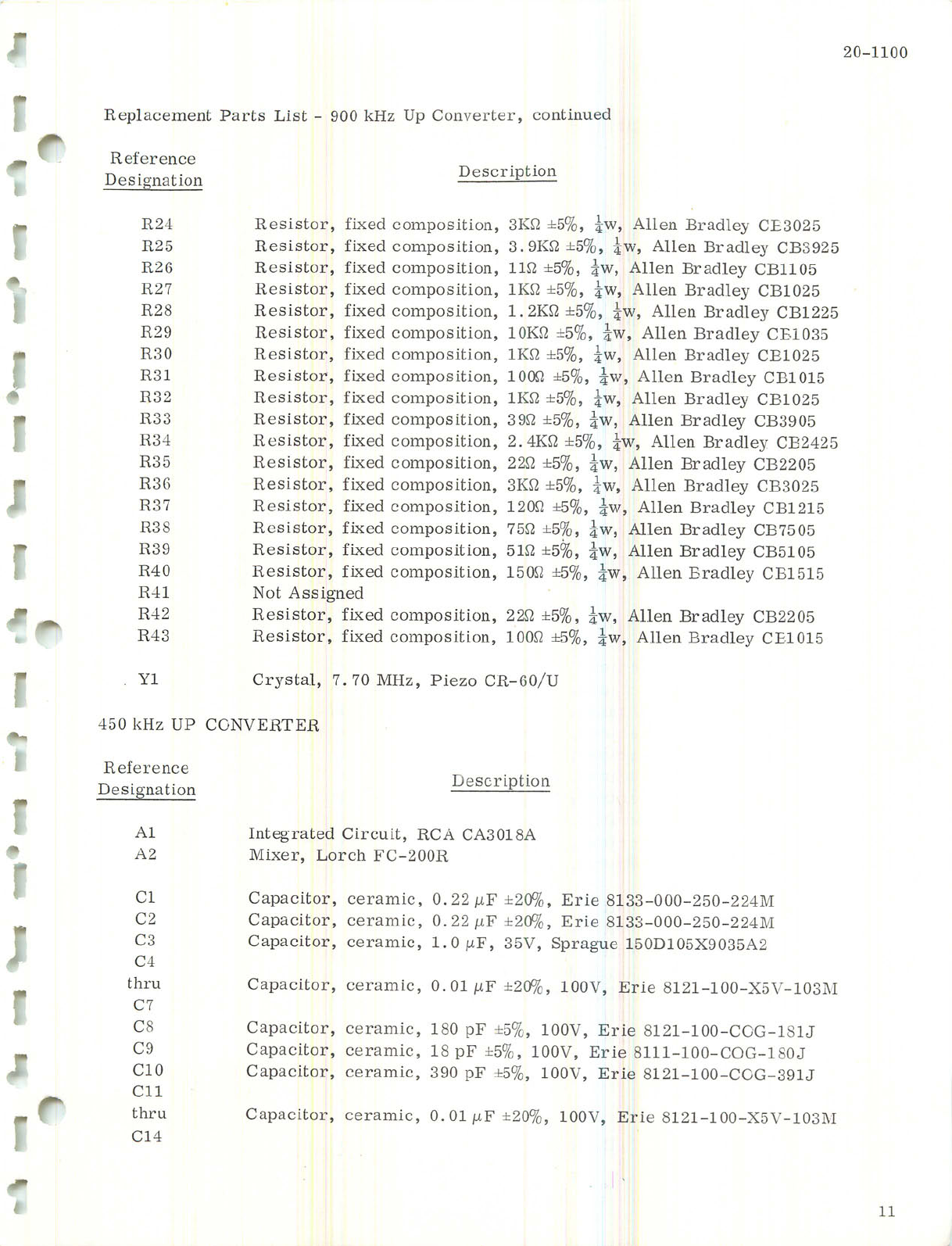
Replacement Parts List - 900 kHz Up Converter, continued
Reference
Designation Description
'R24
R25
R26
R27
R28
R29
R30
R31
R32
R33
R34
R35
R36
R37
R38
R39
R40
R41
R42
R43
Yl
Resistor, fixed
Resistor, fixed
Resistor, fixed
Resistor, fixed
Resistor, fixed
Resistor, fixed
Resistor, fixed
Resistor, fixed
Resistor, fixed
Resistor, fixed
Resistor, fixed
Resistor, fixed
Resistor, fixed
Resistor, fixed
Resistor, fixed
Resistor, fixed
Resistor, fixed
Not Assigned
Resistor, fixed
Resistor, fixed
composition, 3Kft ±5%, iw, Allen Bradley CE3025
composition, 3.9Kft ±5%, iw, Allen Bradley CB3925
composition, lift ±5%, iw, Allen Bradley CB1105
composition, lKft ±5%, iw, Allen Bradley CB1025
composition, 1.2Kft±5%, iw, Allen Bradley CB1225
composition, lOKft ±5%, iw, Allen Bradley CE1035
composition, lKft ±5%, iw, Allen Bradley CE1025
composition, 100ft ±5%, iw, Allen Bradley CB1015
composition, lKft ±5%, iw, Allen Bradley CB1025
composition, 39ft ±5%, iw, Allen Bradley CB3905
composition, 2.4Kft ±5%, iw, Allen Bradley CB2425
composition, 22ft ±5%, iw, Allen Bradley CB2205
composition, 3Kft ±5%, iw, Allen Bradley CB3025
composition, 120ft ±5%, iw, Allen Bradley CB1215
composition, 75ft ±5%, iw, Allen Bradley CB7505
composition, 51ft ±5%, iw, Allen Bradley CB5105
composition, 150ft ±5%, iw, Allen Bradley CB1515
composition, 22ft ±5%, iw, Allen Bradley CB2205
composition, 100ft ±5%, iw, Allen Bradley CE1015
Crystal, 7.70 MHz, Piezo CR-60/U
450 kHz UP CONVERTER
Reference
Designation Description
Al
A2
Integrated Circuit, RCA CA3018A
Mixer, Lorch FC-200R
CI
C2
C3
C4
thru
C7
C8
C9
C10
Cll
thru
C14
Capacitor, ceramic, 0.22/iF±20%, Erie 8133-000-250-224M
Capacitor, ceramic, 0.22iuF±20%, Erie 8133-000-250-224M
Capacitor, ceramic, 1.0/iF, 35V, Sprague 150D105X9035A2
Capacitor, ceramic, 0.01/iF ±20%, 100V, Erie 8121-100-X5V-103M
Capacitor, ceramic, 180 pF ±5%, 100V, Erie 8121-100-COG-181J
Capacitor, ceramic, 18 pF ±5%, 100V, Erie 8111-100-COG-1S0J
Capacitor, ceramic, 390 pF ±5%, 100V, Erie 8121-100-CCG-391J
Capacitor, ceramic, 0.01/iF ±20%, 100V, Erie 8121-100-X5V-103M
11
Courtesy of http://BlackRadios.terryo.org

20-1100
Replacement Parts List - 450 kHz Up Converter, continued
Description
Reference
Designation
C15 Capacitor, ceramic, 0.22/iF ±20%, Erie 8133-000-250-224M
C16 Capacitor, ceramic, 0.22/iF±20%, Erie 8133-000-250-224M
C17 Capacitor, ceramic, 51 pF ±5%, 100V, Erie 8131-100-COG ^
C18 Capacitor, ceramic, 0.22/iF±20%, Erie 8133-000-250-224M
C19 Capacitor, ceramic, 0.01/iF ±20%, 100V, Erie 8121-100-X5V-103M
C20 Capacitor, tantalum, 47 /iF, 20V, Kemet T362C476M020AS
C21 Capacitor, ceramic, 0.01/iF ±20%, 100V, Erie 8121-100-X5V-103M
C22 Capacitor, ceramic, 0.01/iF ±20%, 100V, Erie 8121-100-X5V-103M
C23 Capacitor, ceramic, 2pF±0.1pF, 100V, Erie 8101-100-COG-209B
C24 Capacitor, ceramic, 0.01/iF ±20%, 100V, Erie 8121-100-X5V-103M
C25 Not Assigned
C26 Not Assigned
C37 Not Assigned
C28 Not Assigned
C29 Capacitor, ceramic, 0.01/tF±20%, 100V, Erie 8121-100-X5V-103M
C30 Capacitor, ceramic, 270 pF ±5%, 100V, Erie 8121-100-COG-271J
C31 Capacitor, ceramic, 130 pF ±5%, 100V, Erie 8121-100-COG-121J
C32 Not Assigned
C33 Capacitor, tantalum, 47/iF, 20V, Kemet T362C476M020AS
C34 Not Assigned
C35 Capacitor, ceramic, 0.22/tF±20%, Erie 8133-000-250-224M
C36 Capacitor, ceramic, 0.22/iF±20%, Erie 8133-000-250-224M
C37' Capacitor, tantalum, 10 /iF, 20V, Kemet T362B106M020AS
C 3 8 C a p a c i t o r , c e r a m i c , 3 6 0 p F ± 5 % , 1 0 0 V , E r i e 8 1 2 1 - 1 0 0 - C O G - 3 6 1 J ^
C39 Capacitor, ceramic, 300 pF ±5%, 100V, Erie 8121-100-COG-301J
C40 Capacitor, ceramic, 270 pF ±5%, 100V, Erie 8121-100-COG-271J
C41 Capacitor, ceramic, 130 pF ±5%, 100V, Erie 8121-100-COG-131J _
C42 Capacitor, ceramic, 100 pF ±5%, 100V, Erie 8131-100-COG-101J
C43 Capacitor, ceramic, 100 pF ±5%, 100V, Erie 8131-100-COG-101J
C44 Capacitor, ceramic, 430 pF ±5%, 100V, Erie 8121-100-COG-431J
Ll Inductor, 120 /iH, Jeffers 1315-14J
L2 Inductor, 120 /iH, Jeffers 1315-14J
L3 Inductor, 120 /iH, Jeffers 1315-14J
L4 Inductor, 0.56/tH, Jeffers 4425-3K
L5 Inductor, 2.2/iH, Cambion 7107-17
L6 Inductor, 120 /tH, Jeffers 1315-14J
L7 Inductor, 3.3/iR, Jeffers 4425-12K
L8 Not Assigned
L9 Not Assigned
L10 Not Assigned
Lll Not Assigned
L12 Inductor, 4. 7 /iH, Jeffers 4425-14K "•l
12
Courtesy of http://BlackRadios.terryo.org
20-1100
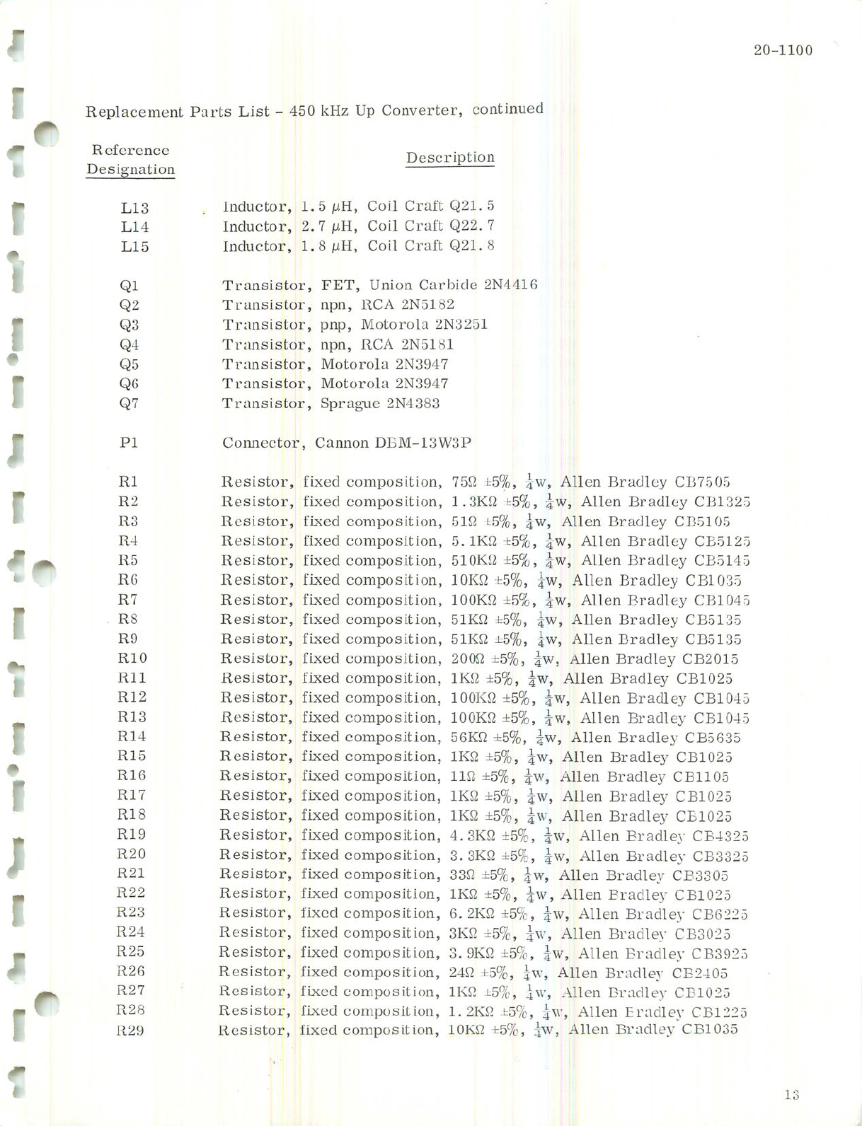
Replacement Parts List - 450 kHz Up Converter, continued
Reference
Designation
L13
L14
L15
Description
Inductor, 1.5/iH, Coil Craft Q21. 5
Inductor, 2.7 /iH, Coil Craft Q22. 7
Inductor, 1.8 /tH, Coil Craft Q21. 8
"
Ql
Q2
Q3
Q4
Q5
Q6
Q7
PI
Transistor, FET, Union Carbide 2N4416
Transistor, npn, RCA 2N5182
Transistor, pnp, Motorola 2N3251
Transistor, npn, RCA 2N5181
Transistor, Motorola 2N3947
Transistor, Motorola 2N3947
Transistor, Sprague 2N4383
Connector, Cannon DBM-13W3P
RI Resistor, fixed composition,
R2 Resistor, fixed composition,
R3 Resistor, fixed composition,
R4 Resistor, fixed composition,
R5 Resistor, fixed composition,
R6 Resistor, fixed composition,
R7 Resistor, fixed composition,
R8 Resistor, fixed composition,
R9 Resistor, fixed composition,
RIO Resistor, fixed composition,
Rll Resistor, fixed composition,
R12 Resistor, fixed composition,
R13 Resistor, fixed composition,
R14 Resistor, fixed composition,
R15 Resistor, fixed composition,
R16 Resistor, fixed composition,
R17 Resistor, fixed composition,
R18 Resistor, fixed composition,
R19 Resistor, fixed composition,
R20 Resistor, fixed composition,
R21 Resistor, fixed composition,
R22 Resistor, fixed composition,
R23 Resistor, fixed composition,
R24 Resistor, fixed composition,
R25 Resistor, fixed composition,
R26 Resistor, fixed composition,
R27 Resistor, fixed composition,
R28 Resistor, fixed composition,
R29 Resistor, fixed composition,
75ft 1=5%, iw, Allen Bradley CB7505
1.3Kft ±5%, iw, Allen Bradley CB1325
51ft t5%, iw, Allen Bradley CB5105
S.lKft ±5%, iw, Allen Bradley CE5125
510Kft ±5%, iw, Allen Bradley CB5145
lOKft ±5%, iw, Allen Bradley CB1035
lOOKft ±5%, iw, Allen Bradley CB104 5
51Kft ±5%, iw, Allen Bradley CB5135
51Kft ±5%, iw, Allen Bradley CB5135
200ft ±5%, iw, Allen Bradley CB2015
lKft ±5%, iw, Allen Bradley CB1025
lOOKft ±5%, iw, Allen Bradley CB1045
lOOKft ±5%, iw, Allen Bradley CB1045
56Kft ±5%, iw, Allen Bradley CB5635
lKft ±5%, iw, Allen Bradley CB1025
lift ±5%, iw, Allen Bradley CB1105
lKft ±5%, iw, Allen Bradley CB1025
lKft ±5%, iw, Allen Bradley CE1025
4.3Kft ±5%, iw, Allen Bradley CE4325
3.3Kft ±5%, iw, Allen Bradley CB3325
33ft ±5%, iw, Allen Bradley CB3305
lKft ±5%, iw, Allen Bradley CB1025
6.2Kft ±5%, iw, Allen Bradley CB6225
3Kft ±5%, iw, Allen Bradley CB3025
3.9Kft ±5%, iw, Allen Bradley CB3925
24ft ±5%, iw, Allen Bradley CE2405
lKft t5%, iw, Allen Bradley CE1025
1.2Kft ±5%, iw, Allen Eradley CB1225
lOKft t5%, iw, Allen Bradley CB1035
13
Courtesy of http://BlackRadios.terryo.org
20-1100
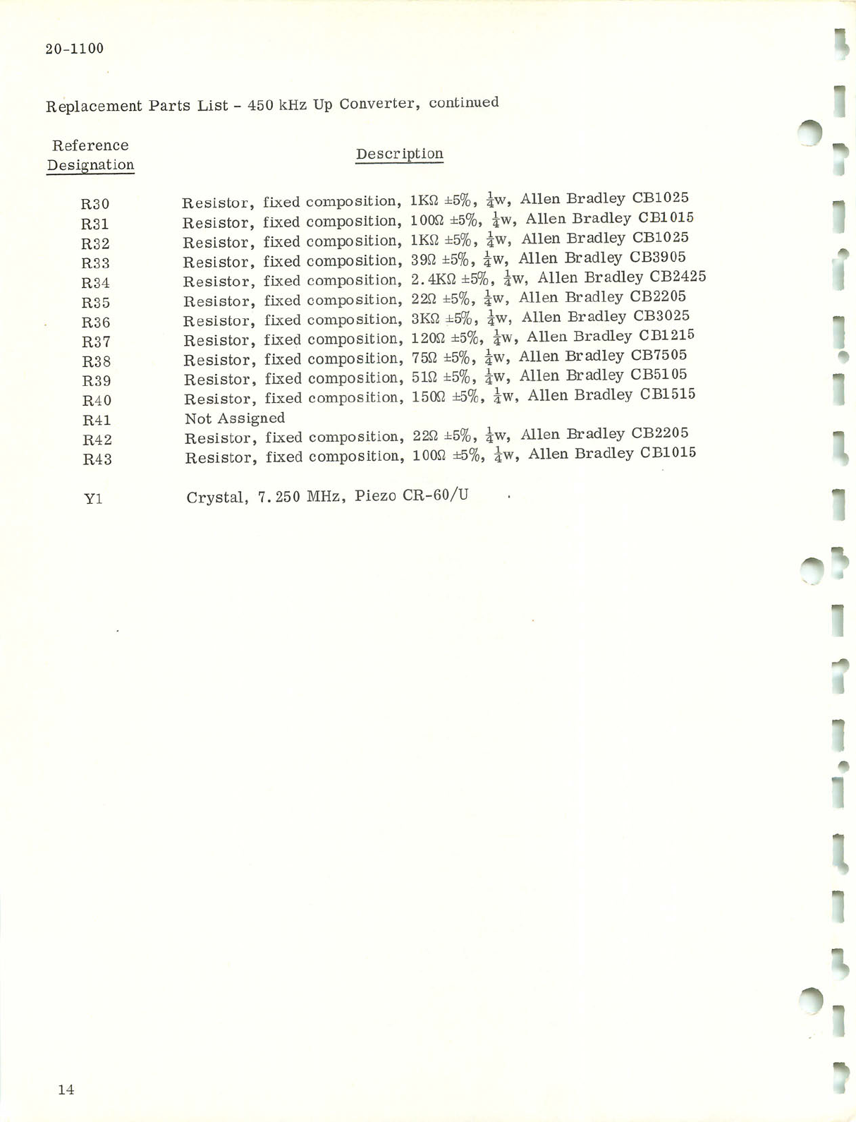
Replacement Parts List - 450 kHz Up Converter, continued
Reference
Designation
R30
R31
R32
R33
R34
R35
R36
R37
R38
R39
R40
R41
R42
R43
Yl
Resistor, fixed
Resistor, fixed
Resistor, fixed
Resistor, fixed
Resistor, fixed
Resistor, fixed
Resistor, fixed
Resistor, fixed
Resistor, fixed
Resistor, fixed
Resistor, fixed
Not Assigned
Resistor, fixed
Resistor, fixed
Description
composition, lKft ±5%, iw, Allen Bradley CB1025
composition, 100ft ±5%, iw, Allen Bradley CB1015
composition, lKft ±5%, iw, Allen Bradley CB1025
composition, 39ft ±5%, iw, Allen Bradley CB3905
composition, 2.4Kft ±5%, iw, Allen Bradley CB2425
composition, 22ft ±5%, iw, Allen Bradley CB2205
composition, 3Kft ±5%, iw, Allen Bradley CB3025
composition, 120ft ±5%, iw, Allen Bradley CB1215
composition, 75ft ±5%, iw, Allen Bradley CB7505
composition, 51ft ±5%, iw, Allen Bradley CB5105
composition, 150ft ±5%, iw, Allen Bradley CB1515
composition, 22ft ±5%, iw, Allen Bradley CB2205
composition, 100ft ±5%, iw, Allen Bradley CB1015
r
-
Crystal, 7. 250 MHz, Piezo CR-60/U
~
I
"
14
Courtesy of http://BlackRadios.terryo.org

20-1100
*
1
r
l
r
Figure 1. Video to 6.8 MHz Up Converter,
Component Location (Typical)
15
Courtesy of http://BlackRadios.terryo.org

91
L
uojqBOOT: quauoduioo
'jaqjaAuoo dfi zrh OS oq 8*9 'Z aJnSjd
t
-
I
00IT-02
Courtesy of http://BlackRadios.terryo.org
Courtesy of http://BlackRadios.terryo.org

Courtesy of http://BlackRadios.terryo.org
Table of contents
Popular Media Converter manuals by other brands


Linear Technology
Linear Technology LTC3129-1 manual

Cisco
Cisco 2000 user guide

Advantech
Advantech BB-422PP9TB quick start guide

B&B Electronics
B&B Electronics IE-Giga-MiniMc Operation manual

SOUNDLIGHT
SOUNDLIGHT DMX Booster/Splitter 3405A-FG operating manual

FibroLAN
FibroLAN MCM1000S-LX1 User and installation guide

CHD Elektroservis
CHD Elektroservis K770-KBD installation manual

Lynx
Lynx C AD 3321 D Reference manual

Texas Instruments
Texas Instruments TPS549B22EVM-847 user guide

B&B Electronics
B&B Electronics PES1A user manual

Miranda
Miranda Quartet Guide to installation and operation

OT Systems
OT Systems FT210DB Series Installation and operation manual