PC1000-PC2000 INSTALLATION MANUAL
10275-8.doc
Polyamp AB, Sweden Page 4 (14)
1 Before installation
Before installation we recommend that you
read this and next section of this manual. If any
problem occurs, consult 12 Trouble shooting.
If the converter includes a fan, please notice 11
Maintenance.
On the front panel label the following is
displayed: Converter type, input voltage range,
nominal output voltage, serial number, options
and article number. The converter type name
consists of model name PC1000, PC1400 or
PC2000 followed by input code and output
voltage. Two examples:
•Type: “PC2000 110/48” has input code “110”
and nominal output voltage 48Vd.c.
•”Type: “PC1000 24/24” has input code “24”
and nominal output voltage 24Vd.c.
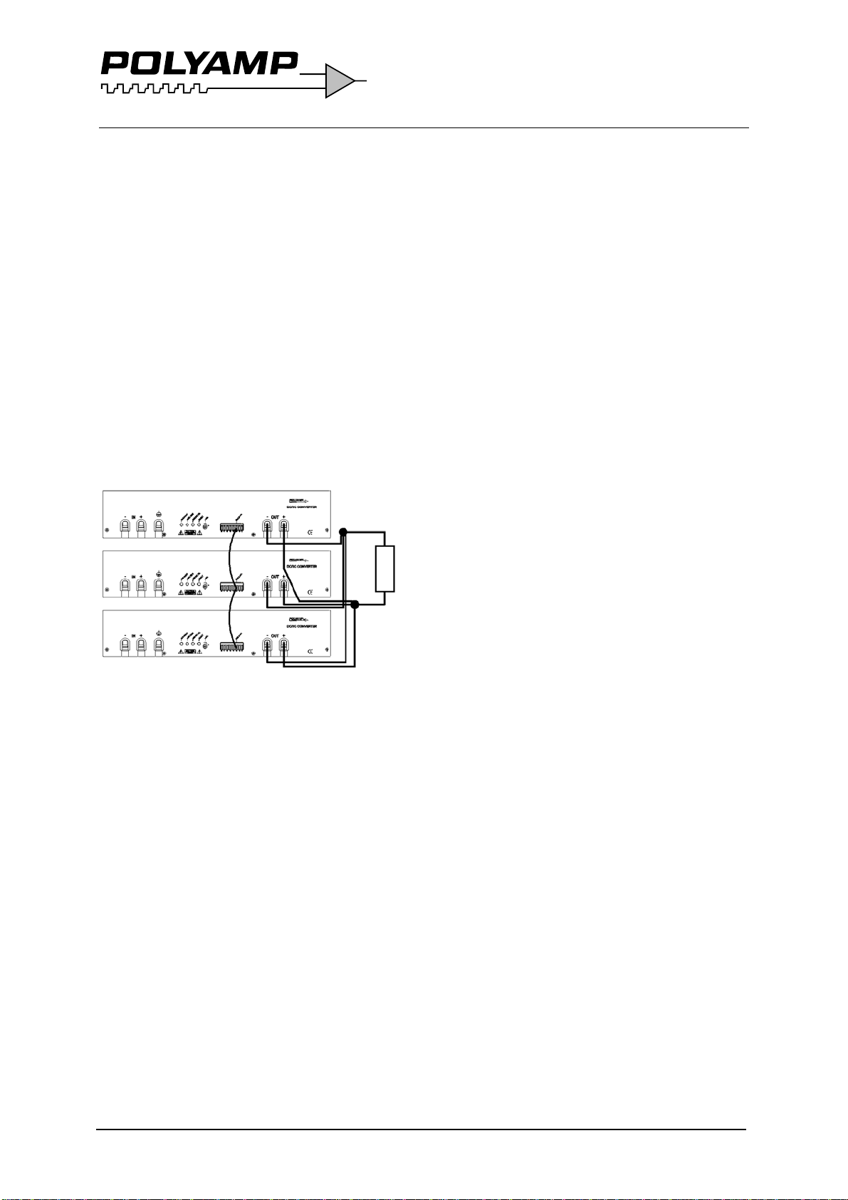
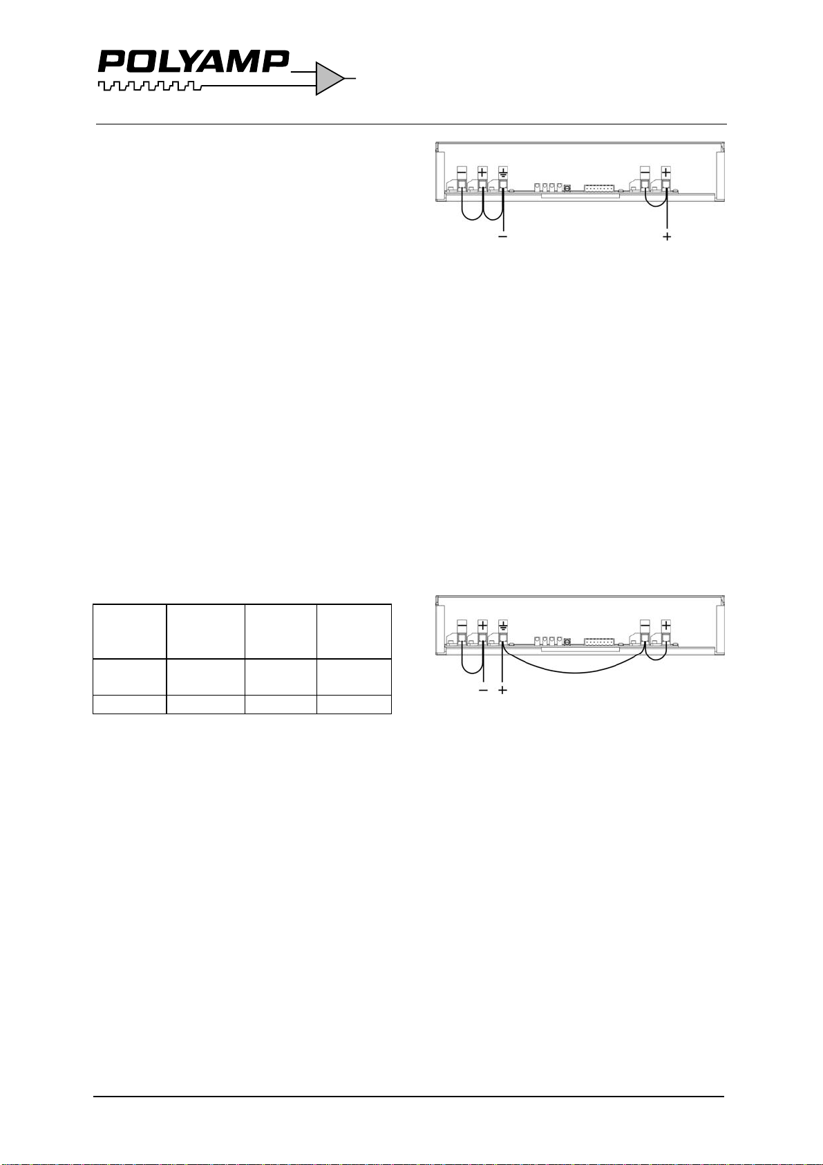
If you intend to parallel connect the output,
please check that option C is supplied. It
means series diode on output.
Input, output and case are galvanically
separated from each other. You can thus
choose how you want the system connected.
The output can be connected with any pole to
protective earth or as a floating output with
max ±150V to the protective earth. It means
that maximum 3 units can be put in series.
The electrical safety system is a class I, which
means that protective earth has to be
connected. The 110 and 220 input code models
can also be used as class II equipment without
protective earth. Although units installed in
dirty environments shall be connected to
protective earth.
On 110 and 220 input code the feeding system
can be defined as Primary circuit (Max
250Va.c.) and as Secondary circuit.
On 24 and 48 input code the feeding system
can be defined as Secondary circuit voltage,
and SELV voltage.
The cables used for input and output feeding
shall be dimensioned to fit the fuse rating and
continuous current as well as intended ambient
temperature range and insulations demand due
to the voltage used.
The input is protected against reverse polarity
by combination circuit with inrush current
limit circuit. If reverse voltage occurs at
installation the converter will not start. The
reverse voltage will not cause damage to the
unit.
The input shall be fused with an approved fuse
with high breaking capacity. We recommend
following fuses ratings and fuses. Please note
that in installation class I with protective earth,
the fuse shall be on the pole not in connection
with the protective earth.
PC1000 input fuses
Input voltage code Time delay fuse
24 63 A, Siemens 3NA3 022
48 35 A, Siemens 3NA3 014
110 16 A, Siemens 3NA3 005
220 10 A, Siemens 3NA3 003
PC1400 input fuses
Input voltage code Time delay fuse
48 50 A, Siemens 3NA3 020
110 20 A, Siemens 3NA3 007
220 10 A, Siemens 3NA3 003
PC2000 input fuses
Input voltage code Time delay fuse
48 63 A, Siemens 3NA3 022
110 25 A Siemens 3NA3 010
220 16 A, Siemens 3NA3 005
Table 1. Recommended input fuses.
There are two reasons we do not include the
fuse.
1. DC-networks should be fused at the
distribution point to protect the cable.
2. Different applications require different
types of fuses.
To meet the EMC specifications in the
enclosed “declaration of conformity” use
twisted-pairs for connecting input, output,
alarm, inhibit and voltage sense. Shielded
cables are not necessary.
If the converter is mounted in an electric
vehicle, an external series diode on the input is
recommended. Please contact your Polyamp
dealer.
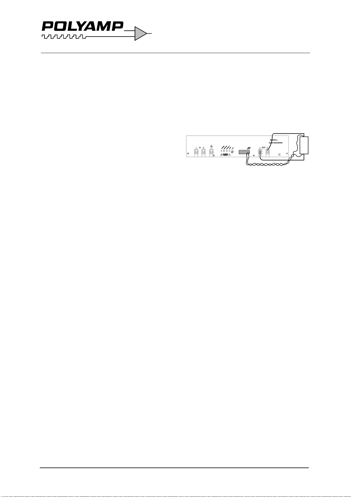
If the converter supplies a DC-motor, we
recommend an external parallel diode at the
motor poles to protect against reverse voltages.