FibroLAN MCM1000S-LX1 Manual

MCM1000S/L
Module Converter/Extender
1000Base-SX/LX to 1000Base-LX
User and Installation Guide
Version: 2.4
FibroLAN Ltd.
2 Carmel St. P.O. Box 544 Yokneam-Illit, 20692 ISRAEL
Tel: 972-4-9591717 Fax: 972-4-9591718

MCM1000S/L GBE module
2
FEDERAL COMMUNICATIONS COMMISSION
AND
CANADIAN DEPARTMENT OF COMMUNICATIONS
RADIO FREQUENCY INTERFERENCE STATEMENTS
This equipment generates, uses, and can radiate radio frequency energy and if not
installed and used properly, that is, in strict accordance with the manufacturer’s
instructions, may cause interference to radio communication. It has been tested
and found to comply with the limits for a Class A computing device in accordance
with the specifications in Subpart B of Part 15 of FCC rules, which are designed to
provide reasonable protection against such interference when the equipment is
operated in a commercial environment. Operation of this equipment in a
residential area is likely to cause interference, in which case the user at his own
expense will be required to take whatever measures may be necessary to correct
the interference.
Changes or modifications not expressly approved by the party responsible for
compliance could void the user’s authority to operate the equipment.
This digital apparatus does not exceed the Class A limits for radio noise emission
from digital apparatus set out in the Radio Interference Regulation of the Canadian
Department of Communications.
Le présent appareil numérique n’émet pas de bruits radioélectriques dépassant les limites
applicables aux appareils numériques de la classe A prescrites dans le Règlement sur le brouillage
radioélectrique publié par le ministère des Communications du Canada.
CE Mark
The CE mark symbolizes compliance with the European Community
required technical standards.
The product herewith complies with the requirements of the EMC Directive
89/336/EEC,the Low Voltage Directive 73/23/EEC and the R&TTE Directive
99/5/EC.
The product was tested in a typical configuration.
Levy Malkiely
Quality Manager

MCM1000S/L GBE module
3
Table of contents
General Description page 4
Features Summary page 4
Product list page 5
MetroStar Chassis Layout page 6
Module Front Panel page 7
Installation procedures page 8
F/O cabling connection page 9
F/O ports Specifications page 10
MA™ Concept and Functions page 11
MMM-4 Management module page 12
DIP switches setting page 13
LST (Link Segmentation Test page 14
SLE (Subscriber Link Emulation) page 16
Typical Configuration page 17
Troubleshooting page 18
Specifications page 19
Module default settings page 19
Warranty Limitation page 20
Thank you for purchasing the MCM1000S/L GBE
Module Converter/Extender from FibroLAN.
We hope that this guide will help you to obtain
the best results from the device while minimizing
installation time.
If you still need help installing or troubleshooting the MCM1000S/L
converter after reading the detailed information in this guide, please visit our
web site, contact your reseller, or call FibroLAN directly.
(Support @fibrolan.com; Tel: +972-4-9591717; Fax: +972-4-9591718)
TRADEMARKS
Any trademarks mentioned in this manual are acknowledged to be the property of the
trademark owners.

MCM1000S/L GBE module
4
1 –General Description
This module provides conversion from a fiber-optic multimode GBE link (1000Base-SX)
to a Single Mode Link (1000Base-LX) to allow extension of up to 80km. The
MCM1000S/L is based on a full digital technology: signals from one F/O port are
converted to digital electrical signals, fully retimed, then converted again to F/O and
transmitted from the second port. This design provides a resilient conversion, advanced
control and diagnostic features. In addition it facilitates special applications like daisy
chaining, back-to-back and management. Port 1 is 1000Base-SX or LX type. Port 2 is
defined as 1000Base-LX for link distances and is normally connected to a remote unit.
The module may act as an Extender Media Converter if Port 1 is 1000Base-LX type.
(Refer to section 3 for a complete list of available GbE modules)
Single Fiber Strand modules (SX/LX 20, 40Km) are also available.
Link Segmentation Test (LST) allows easy link test segmentation (LST ON=Test mode)
to locate a failed link segment and in LST OFF mode (Fault Propagation mode) the shut
down of the entire link if one of the F/O link is disrupted and Network Device notification
of the link failure. A front panel LED will show the LST setting for each F/O port.
A Loop-Back function (for each port) simplifies troubleshooting of link problems.
Incoming received data on the RX port is looped back and transmitted from the TX port.
Each port provides separate Link and Activity indications for enhanced diagnostics.
Like other MetroStar modules, the MCM1000S/L is fully SNMP managed. All MetroStar
modules are hot swappable. A special LED indicates that the module is well inserted in
its slot and “alive” even before links are established. The MCM1000S/L module is
managed via the MetroStar Management module. (MMM-01or MMM-04 module)
The embedded MA™ (Micro Agent) is an on chip management system enabling the
management of remote access devices eliminating the need of a SNMP agent and IP
address. When the MCM1000S/L module is connected through its F/O link to a remote
device, which is MA™ enabled, a comprehensive set of monitoring and control functions
can be implemented from the SNMP management module (located in the MetroStar) into
the attached remote MA devices.
The MCM1000S/L modules family supports another unique outstanding feature: SLE
(Subscriber Link Emulation) enabled through the system management (for a detailed
description, refer to section 11)
2 –Features Summary
Two fiber (1000Base-SX/LX to 1000Base-LX) ports
Conversion method: Direct Digital with LST capability
SNMP managed including Telnet
MMM-04 Management :SNMP, Web, CLI (Console, Telnet, SSH)
Remote MA devices management. Front panel MA Active LED
Covered distance: up to 120Km point to point, more if cascaded
Single Fiber Strand (SFS) modules (up to 20, 40Km)
LST: Link Segmentation Test for each port: allows to locate a failing segment
within a network
F/O Loop Back for each F/O port
Diagnostics LED indicators for Link and Activity monitoring each F/O port
On board DIP switches for LB (loop-back) and LST for each F/O port
Supports SLE (Subscriber Link Emulation) through system management
Supports OFC (Offline Configuration Facility)

MCM1000S/L GBE module
5
3 –Product List
The MCM1000S/L module is offered in the following preconfigured versions:
MCM1000S-LX1
1000SX multi-mode 850nm, 220m, to 1000LX single mode 1310nm Conversion
Module, 10km, 2*Duplex SC, MA
MCM1000S-LX2
1000SX multi-mode 850nm, 220m, to 1000LX single mode 1310nm Conversion
Module, 20km (over G.652 fiber), 2*Duplex SC, MA
MCM1000S-LX3
1000SX multi-mode 850nm, 220m, to 1000LX single mode
1550nmDFBTx/1550nmRx, Conversion Module, 40km. 2*Duplex SC, MA
MCM1000S-LX4
1000SX multi-mode 850nm, 220m, to 1000LX single mode
1550nmDFBTx/1550nmRx, Conversion Module, 80km. 2*Duplex SC, MA
MCM1000S-LXF13
1000SX multi-mode 850nm, 220m, to 1000LX Single Fiber Strand,
1310nmTx/1550nmRx, Conversion Module, 20km (over G.652 fiber),
1xduplex/1xsimplex SC, MA
MCM1000S-LXF15
1000SX multi-mode 850nm, 220m, to 1000LX Single Fiber Strand,
1550nmDFBTx/1310nmRx, Conversion Module, 20km (over G.652 fiber),
1xduplex/1xsimplex SC, MA
MCM1000S-ZXF13
1000SX multi-mode 850nm, 220m, to 1000LX Single Fiber Strand,
1310nmTx/1550nmRx, Conversion Module, 40km (over G.652 fiber),
1xduplex/1xsimplex SC, MA
MCM1000S-ZXF15
1000SX multi-mode 850nm, 220m, to 1000LX Single Fiber Strand, 1550nmDFBTx/
1310nmRx, Conversion Module, 40km (over G.652 fiber), 1xduplex/1xsimplex SC,
MA
MCM1000L-LX1-2
1000LX single-mode 1310nm, 10Km to 1000LX single-mode 1310nm Extender
module 20Km (over G.652 fiber), 2*Duplex SC, MA
MCM1000L-LX1-3
1000LX single-mode 1310nm, 10Km to 1000LX single-mode 1550nm DFB Extender
module 40Km, 2*Duplex SC, MA
MCM1000L-LX1-4
1000LX single-mode 1310nm, 10Km to 1000LX single-mode 1550nm DFB Extender
module 80Km, 2*Duplex SC, MA
MCM1000L-LX3-3
1000LX single-mode, 1550nmDFBTx/1550nmRx, 40Km to 1000LX single-mode
1550nmDFBTx/1550nmRx, Extender module 40Km, 2*Duplex SC, MA
MCM1000L-LX4-4
1000LX single-mode, 1550nmDFBTx/1550nmRx, 80Km to 1000LX single-mode
1550nmDFBTx/1550nmRx, Extender module 80Km, 2*Duplex SC, MA
MCM1000L-LX4-5
1000LX single-mode 1550DFB, 80Km to 1000LX single-mode 1550nm DFB/APD
Extender module, 120Km, 2*Duplex SC, MA
All MCM1000S/L series modules have identical functionality. Therefore, any description
and features of one module refers to all other types.
The F/O ports supports GBE 1000Base-SX/LX transmissions, set to 1000Base-FX and
FDX (Full Duplex). Any network device which connects to the F/O ports of
MCM1000S/L module should be configured to Auto-Negotiation disabled mode
(forced to 1000Base-FX and FDX) to obtain the link connectivity.
The modules incorporate on board DIP switches (LST ON/OFF, Loop-Back ON/OFF)
per port to easily perform troubleshooting and maintenance functions.
Recall that Port 1 (normally 1000Base-SX type port) can be offered as 1000Base-LX
port (MCM1000L-LX Extender series).
Port 2 (1000Base-LX) is normally connected to a remote GBE device.
The MCM1000S modules, installed in the MetroStar System chassis, can be managed
locally through the serial connection (CLI) or a Telnet connection through a SNMP
Manager station. With MMM-04 module, Web management is also available Refer to
section 8 for more details.
The module is managed also by the FibroLAN MetroView Device Manager.
Note: the firmware or software update for the various MetroStar modules and
remote MA CPE devices is implemented by means of the TFTP routine.

MCM1000S/L GBE module
6
4 –MetroStar Chassis Layout
1 2 3 41512
In slot position # 3 (from the left), it is possible to install a additional redundant
Power Supply or the Blank panel BP-02.
Slot position # 4 is normally dedicated for the MetroStar™SNMP management
module (MMM-01or MMM-04) for standalone MetroStar™. The PMM module is
normally installed in slot # 4 in unmanaged MetroStar™System (optional module)
When the MetroStar™chassis is not fully populated with conversion modules, it is
mandatory to install the BP-01 Blank Panel in the vacant slots.
In slot position # 3 (from the left), it is possible to install an additional redundant
Power Supply or the Blank panel BP-02.
MCM1000S/L GBE module
7
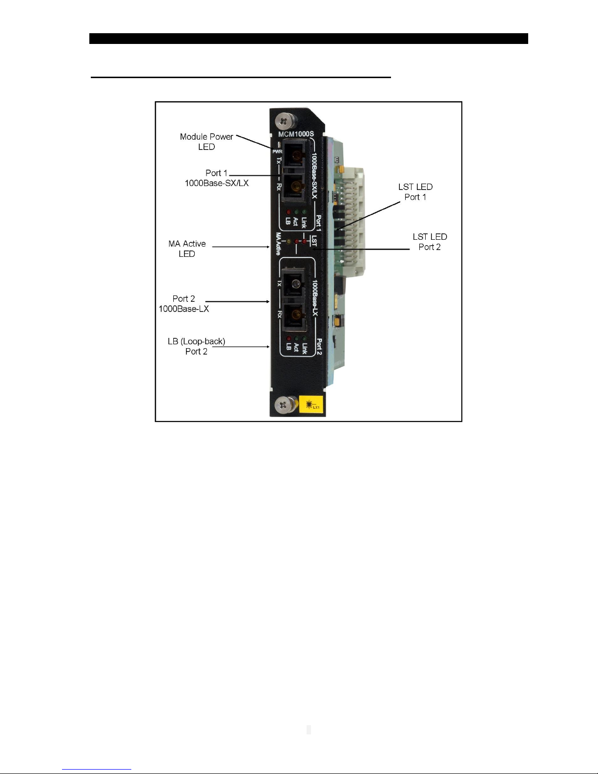
5 –Module front panel - Parts Identification
1. Port 1 LEDs:
Link: steady green lit: a F/O link has been established.
Act: port 1 activity. Blinking green (receive / transmit)
LB: lit red implies port 1 is in loop-back mode
2. Port 1 Duplex SC fiber optic connector: (left /Tx, right / Rx)
3. System LED indicators:
Port 1 LST: lit red implies that an idle signal is sent from port 1 (S4 UP, LST ON)
when data is not transmitted at the same time.
Port 2 LST: lit red implies that an idle signal is sent from port 2 (S3 UP, LST ON)
when data is not transmitted at the same time.
MA active: steady lit (amber): the MCM1000S module is connected to a remote
enabled MA and active device.
4. Port 2 Duplex SC fiber optic connector: (left /Tx, right / Rx)
5. Port 2 LEDs:
Link: steady green lit: a F/O link has been established.
Act: port 1 activity. Blinking green (receive / transmit)
LB: lit red implies port 2 is in loop-back mode
6. Power ON/OFF green LED indicator (PWR LED)

MCM1000S/L GBE module
8
6 –Installation procedures
Slot assignment
MCM1000S/L modules may be installed in any of the slots marked 1 to 12,however by
installing modules systematically next to each other (from left to right) it will make it
easier to install additional modules in the future allowing clear access to the slots.
Installation of Modules
All MetroStar™ modules are hot swappable however it is recommended – whenever
operationally acceptable, to install a module (or swap an already installed module) while
the system is powered OFF.
All modules are equipped with two self-clinching screws –always use BOTH of them for
safe insertion and removal of modules into/from the system.
To install a module in a vacant slot: remove the blank panel covering the slot using a
crosshead screwdriver. Hold the module vertically with one hand by the side facets of the
metal frame of the module. Do not touch the PCB (printed circuit board) or any of the
components with your hand. The frame is asymmetrical: its bottom end rectangular while
its other side has a diagonally “cut” edge – make sure this side is up. Align both upper
and lower edges of the PCB with the lower and upper Nylon guides of the slot and gently
glide the module into the slot, applying only a small pressure. If correctly positioned and
aligned, it should allow the module all the way in. At the final stage (2-3 mm short of full
insertion) you will experience a slightly higher resistance –apply a higher pressure with
your finger on the panel of the module till you feel it “clicks in” and its panel is flush with
the surface of the chassis. At this point, if the MetroStar™ is powered ON the PWR LED
(left-upper side of the module or any corresponding LEDs on the PMM) will light. If not lit,
ensure that unit is powered UP; if still not lit –remove the module and re-insert. Is
problem persists; troubleshoot by inserting same module in a different slot and/or
another module in the suspected slot. Fasten both self-clinching screws using your
fingers by turning them clockwise, while doing that an increasing resistance indicates
that the screw is well aligned with it’s nut. Finally, using a crosshead screwdriver fasten
both screws (normally no more than one full turn will be required). Make sure not to
apply excess power.
To Swap a module: Unfasten the 2 screws using a cross-head screwdriver then
continue by turning them with your fingers counter-clockwise till the head of the screw
“pops out”. Hold both screws with fingers of BOTH hands and pull the module out.
Ensure applying balanced force at both screws to maintain vertical position throughout
the process, although it might be necessary to slightly tilt the module at the very first mm.
Continue as above to insert the new module. If you choose to leave the slot vacant,
always close it with a blank panel.
Warning: Do not INSTALL a module into a slot with already attached TP/F/O cabling.
Connect the cables to the module ports only after having verified that the module is well
inserted and its Power LED is lit.
Conversely, DISCONNECT the TP/F/O cabling from the module ports before replacing it. Non-
compliance with the above procedure may cause module's malfunction.
General considerations for MetroStar MCM1000X modules
The MetroStar™ system is delivered by default equipped with 2 power supplies –either
AC or DC. A third - redundant power supply module is optional. Each P.S. provides 14A.
The PS modules (2 or 3 if the optional is installed) are operating in a load-sharing mode;
therefore even the first 2 PS modules may provide a redundancy effect. The MCM1000S
when loaded with 2 FO transceivers needs 1.3 amperes. If 12 such modules are installed,
then the third P.S should be added, if redundancy is needed. With Up to 10 MCM1000S
modules, two P.S provide redundancy.

MCM1000S/L GBE module
9
7 –Fiber Optic Connection
The MCM1000S/L modules are equipped with two SC-type connectors.
Do not remove the protective covers on the fiber connectors until you are ready to
connect the fiber optic cables. Power should be connected (install the module into a
MetroStar slot) before attaching the fiber optic cables. When dealing with fiber optic
cables, it is essential to ensure that the Tx at one end of the link is connected to the Rx
at the other end of the link. Some duplex fiber optic cables are color coded to help
monitor the direction of data transmission. If the fibers are not coded, special attention
must be paid to ensure a proper connection. If your distance is shorter than specified in
the table below (see next page) for your model or should you wish to perform a local test,
insert first in line (both receive and transmit) appropriate attenuators (5db should suffice).
CAUTION
Radiation emitted from a fiber optic connector may be
hazardous to human vision. Therefore, the following rules
must be strictly observed.
All single-mode (SM) models are CLASS I LASER PRODUCTS
and must be handled with special care
When not in use, keep the fiber optic connector closed using
its protective cover.
The fiber optic transmitter is a CLASS 1 Laser product that
may endanger your eyes
Never stare directly into the fiber optic connector of a powered
device or into the end of a fiber connected to it.
Do not look directly into the fiber optic cables or transmitter
Laser Safety
The emissions produced by the end products described in this guide are under Class 1 emission
level according to IEC 60825-1 and the FDA 21 CFR 1040.10 and 1040.1. These products shall not
be installed in an optical network handling above Class 1 level.

MCM1000S/L GBE module
01
F/O ports specifications
Model
Port 1
Port 2
Minimal
Output
Power
dBm
Minimal
Receive
Sensitivity
dBm
WL
nm
Minimal
Output
Power
dBm
Minimal
Receive
Sensitivity
dBm
WL
nm
Suggested
DistanceKm
MCM1000S-LX1
-9.5
-19
850
-11
-20
1310
0,2/ 0-10
MCM1000S-LX2
-9.5
-19
850
-7
-20
1310
0,2 / 5-20
MCM1000S-LX3
-9.5
-19
850
-5
-23
1550/DFB
0,2 /10-40
MCM1000S-LX4
-9.5
-19
850
0
-24
1550/DFB
0,2 /25-80
MCM1000L-LX1-2
-11
-20
1310
-7
-20
1310
0-10/10-20
MCM1000L-LX1-3
-11
-20
1310
-5
-23
1550/DFB
0-10/10-40
MCM1000L-LX1-4
-11
-20
1310
-0
-24
1550/DFB
0-10/25-80
MCM1000L-LX3-3
-5
-23
1550DFB
-5
-23
1550/DFB
10-40/10-40
MCM1000L-LX4-4
0
-24
1550/DFB
0
-24
1550/DFB
25-80/25-80
MCM1000L-LX4-5
0
-24
1550/DFB
0
-32
1550/DFB/
APD
25-80/80-120
MCM1000SLXF13
MCM1000SLXF15
-9.5
-19
850/850
-9
-21
1310/1550
1550DFB /
1310
0,2/ 5-20
MCM1000SZXF13
MCM1000SZXF15
-9.5
-19
850/850
-3
-22
1310DFB/15
50
1550 DFB/
1310
0,2/ 10-40
MCM1000S/L GBE module
00
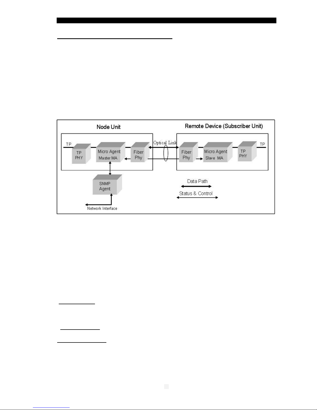
8 –MA Concept and Functions
The MA™ (Micro Agent) is an on-chip management system providing the monitoring
and management of remote access devices without the need of an expensive
SNMP agent module. The MA™ does not require an IP address
The chip is embedded in both the remote units, mostly referred to as a CPE, and in
the access concentrator device deployed in the access node. A unique secured in-
band management protocol allows the two devices communicating between
themselves over the fiber link bi-directionally, therefore both monitoring and
management commands can be remotely performed on the CPE. Control frames
are not forwarded to data ports
Micro Agent Basic System Block Diagram
When MA™ enabled devices are deployed at both ends of the fiber link, they
automatically learn about each other’s presence and begin providing full remote
management functions within 20 to 30m.seconds from the moment the link has
been established. However, if an MA™ enabled devices cannot complete such
handshake within that time, it concludes that the opposite end device is not MA™
enabled, subsequently it bypasses its special functions and operates like a
standard, straight forward access device. Therefore there are no interoperability
issues between network devices which have MA™ chips embedded in them and
those that have not.
The following management functions are available for the MCM1000S/L
module through an MA™ enabled and SNMP managed MetroStar:
Module status: display the MCM1000S/L ports basic status and configuration
settings Link status (SX and LX), Signal Detect status (SX and LX), Channel’s enable
(LX), LST modes, Loop-back (SX and LX), SLE modes, Remote MA device type and
Power status)
Module Control: provides the user with options to set the channel’s description,
LB/LST control, enable/disable channel, and to restore the module’s defaults setting.
Link management: related to the complete MA link including both ends,
the module channel on the local side and the remote CPE MA device:
Link Status, Set link bandwidth, Enable/Disable Up/Downstream SLE, invoke MA
remote device menu, Restore link default parameters.
Note: for a detailed description, please refer to the MMM-01 Management
Manual (version 1.6.2 and up).

MCM1000S/L GBE module
02
9 –MMM-04 enhanced management module
The MCM1000S/L module may also be managed via the MMM-04 management module.
The new module is aimed at replacing the MMM-01 module currently operating with the
MetroStar System.
The need to redesign and replace the MetroStar management module has emerged from
two main reasons:
Processor –a more powerful processor is used
Operating System - using a newer OS provides the foundation for a more flexible system,
with extended capabilities.
Features and Characteristics:
Linux operating system
SNMP V1, V2c, MIB II
(RFC1213/1215, RFC1514)
Web Management
IPv4
SSHv1/2
Telnet
FTP/TFTP client
RADIUS
Syslog and local logging
NTP V1-V4
Manages ALL line modules and
remote devices
Single slot, hot swappable
Remote S/W upgrade
2xRJ-45 for network
connection and for Console
Diagnostic LEDs
Alarms, programmable filtering
Comprehensive Statistics

MCM1000S/L GBE module
03
10 –DIP switches setting.
Each MCM1000S/L module is equipped with an array of 4 DIP switches that facilitate the
proper testing and setting of the F/O ports for optimal operation.
The DIP switches array is located on the motherboard. The module may contain either a
“piano” like array of DIP switches (blue color) or an array of slide switches (black color).
The following operations can be implemented on each F/O port:
Loop-back enable / disable
Link segmentation test: LST ON (Test mode), LST OFF (Link failure notification)
NOTE: The MA management overrides the DIP switches setting
UP –loop-back enable - port 1
UP –loop-back enable - port 2
Down –loop-back disable - port 1
Down –loop-back disable - port 2
UP –Test Mode - port 1 to port 2
Up –Test Mode - port 2 to port 1
Down - LST OFF - port 1 to port 2
Down - LST OFF - port 2 to port 1
LB=Loop-back
LST= Link Segmentation Test
Default DIP switches set-up:
S1,S2 in Down position (LB disabled)
S3,S4 in UP position ( LST ON=Test Mode)
Up
Down
TP F/O
Port Setup
LB LST
S1 S2 S3 S4
TP F/O
ON
OFF
Black Type DIP slide switches
1 2 1 2
Port Setup
LB LST
S1 S2 S3 S4
Blue Type DIP switches
Default DIP slide switches
set-up:
S1,S2 ON ( LB disabled)
S3,S4 OFF( LST ON=Test Mode)
The various settings are exactly
the same as those described
for the Blue Type DIP switches
Recall that UP position (in Blue
DIP switch) = OFF (in Black type
DIP switch) , Down=ON
Note: prior to power on the device, ensure that the DIP switches are in Default mode
LB (loop-back)
In normal operation, the LB DIP switches are in disable mode (DOWN position)
When it is necessary to perform a loop-back test in the selected port, then the
associated LB DIP switch should be enabled (UP position). The appropriate
LB LED will light to indicate that the selected MCM1000S port is in loop-back mode.
Before applying power to the module, ensure that the LB DIP switches are down.
LST (Link Segmentation Test)
The LST DIP switches have two positions per port. As long as no link failure is detected,
data is communicated normally.
When the DIP switches (S3 and S4) are in down position, this is the LST OFF mode of
operation. If a link failure occurs on one port, a signal is transmitted through the network;
the signal will turn off the link indicators on its way to the remote Network Device, which
is alerted and notified of the Link failure.
When the LST DIP switches are changed to Test Mode (UP position, LST ON) and there
is a link failure an idle signal is propagated in the network. This mode is used to identify a
failed link segment. In Test mode, the LST LED will lit (for each DIP switch S3 and S4)
Refer to next pages for a detailed explanation.

MCM1000S/L GBE module
04
11 –Link Segmentation Test (LST)
The MCM1000S is equipped with a powerful link status alert and link testing mechanism
-the “ Link Segmentation Test “, which allows the user to determine the behavior of the
MCM1000S media converter when a link failure is detected and notify the Network
Device on the integrity of the link. Thus the LST provides a view into what goes on
between two attached converters. It monitors the link status of a connection and forwards
this info to the Network Device. Network Devices are therefore aware of the link loss
on the “ other side “ of the converter and can select an alternate path.
In low cost GBE converters, a link failure at one port will cause the entire link to fail
without any notification and alertness of the link failure.
The MCM1000S module has two DIP switches for each direction where the LST function
is required as shown in figure-1.
Figure –1 depicts the sequence of events when the LST DIP switches are in LST OFF
position and the link between Network Device B and the GSM1000/MA has failed.
Figure –1 LST OFF (Link failure notification)
1. The LST DIP switches (S3 and S4) in GSM1000/MA and MCM1000S module are in
LST OFF (Down position).
The active MA will override the setting of the DIP switches in GSM1000/MA
and the default values are established by the MMM-01 SNMP management
module installed in the MetroStar system. Therefore you have to setup the DIP
switches in GSM1000/MA from the remote management agent.
2. The LST in OFF mode will disconnect the entire link in the following events:
a. When a link failure takes place between Network Device B and GSM1000/MA,
the device GSM1000/MA detects a Link Down condition and transmits a signal to
MCM1000S module. This causes a Link Down condition at MCM1000S module
which will consequently disconnect the fiber link to Network Device A.?
Network Device A is thus alerted that a Link failure has occurred in the network.
b. Same events will take place (in opposite direction) in case that the link between
Network Device A and the MCM1000S module fails.
c. If both the fiber links (1000Base-LX) fail between the MCM1000S module
and the GSM1000/MA, appropriate signals are transmitted to both remote
Network Devices alerting them that there is a link failure.
A link down condition will thus occur between the MCM1000S and GSM1000/MA
and their attached Network Devices.
3. The LST in Test Mode (LST DIP switches in UP position) is used to isolate a failed
link segment. In Test mode an idle signal is transmitted which will turn on the
Link indicators of the intact link segments (provided that no data flow is taking
place at the same time.)

MCM1000S/L GBE module
05
In Test mode, as long as no link failure is detected, data is communicated normally.
In case of a link failure in LST OFF mode, the Test Mode will provide a visual
indication of the active and operative links and indicate the failing link segment.
Figure- 2 (below) depicts the sequence of events when the LST DIP switches are
changed to Test Mode, following a link failure occurred in LST OFF mode.
S3
S4
S4
N
E
T
W
O
R
K
D
E
V
I
C
E
N
E
T
W
O
R
K
D
E
V
I
C
E
MCM1000S GSM1000/MA
TX TX TX
TXRX
RX
TX RX
RX
RX
AB
P
O
R
T
1
P
O
R
T
2
P
O
R
T
2
P
O
R
T
1
S3
Idle signal
TX
RX
Link On
Idle signal
Link On
Link Segment OK Link Segment OK Failed Link
1000Base-LX
1000Base-SX 1000Base-SX
MetroStar
S3
S4
S4
N
E
T
W
O
R
K
D
E
V
I
C
E
N
E
T
W
O
R
K
D
E
V
I
C
E
MCM1000S GSM1000/MA
TX TX TX
TXRX
RX
TX RX
RX
RX
AB
P
O
R
T
1
P
O
R
T
2
P
O
R
T
2
P
O
R
T
1
S3
Idle signal
TX
RX
Link On
Idle signal
Link On
Link Segment OK Link Segment OK Failed Link
1000Base-LX
1000Base-SX 1000Base-SX
S3
S4
S4
N
E
T
W
O
R
K
D
E
V
I
C
E
N
E
T
W
O
R
K
D
E
V
I
C
E
MCM1000S GSM1000/MA
TX TX TX
TXRX
RX
TX RX
RX
RX
AB
P
O
R
T
1
P
O
R
T
1
P
O
R
T
2
P
O
R
T
2
P
O
R
T
2
P
O
R
T
2
P
O
R
T
1
P
O
R
T
1
S3
Idle signal
TX
RX
Link On
Idle signal
Link On
Link Segment OK Link Segment OK Failed Link
1000Base-LX
1000Base-SX 1000Base-SX
MetroStar
Figure –2 LST ON - Test Mode
4. Isolation of a failed link segment:
a. To isolate the failed link segment (between the GSM1000/MA and the Network
Device B, the LST DIP switch S4 in MCM1000S module is turned ON
(Test mode) via the remote management
This action generates an idle signal to be transmitted from MCM1000S to
Network Device A turning On the Link at Network Device A. This indicates
that the link segment between the MCM1000S module and Network Device
A is operative.
b. The DIP switch S3 (port1>port2) at the GSM1000/MA device must be physically
set to Test Mode which in this case will cause the F/O Link LED at
MCM1000S/L (port2) to lit (Link ON)
This indicates that the link segment between the MCM1000S and GSM1000/MA
is intact and operative.
c. The above tests are an absolute indication that the failure is in the link segment
between the Network Device B and the GSM1000/MA port 1
d. After having located and repaired the failing segment, it is advisable to turn the
MCM1000S LST DIP switches to their default setting.
Notes (when GSM1010/MA or GSM1000/MA acts as a remote device ):
To preserve the link integrity for the MA inband management, the DIP switch S3
and S4 (in GSM1000/MA or GSM1010/MA) are by default set to Test Mode (LST ON)
Similar default setting applies to the MCM1000S module.
5. The correct deployment of the LST mode of operations in the FibroLAN MA managed
devices depends primarily on the network topology.
If the attached Network Devices (switches, routers) can provide an alternate path in case
of a link failure, then it is advisable and recommended to deploy the LST OFF mode (in
this case the Network Device is alerted of a link failure).
In case of a link failure, it is necessary to switch to Test mode in order to locate the failed
link segment. (via DIP switches or appropriate MA management commands)
6. On the other hand, if the attached Network Devices are dumb units and are unable to
provide an alternate path, then it is recommended to deploy the LST DIP switches in
Test mode (LST ON) which is the default setting.
MCM1000S/L GBE module
06
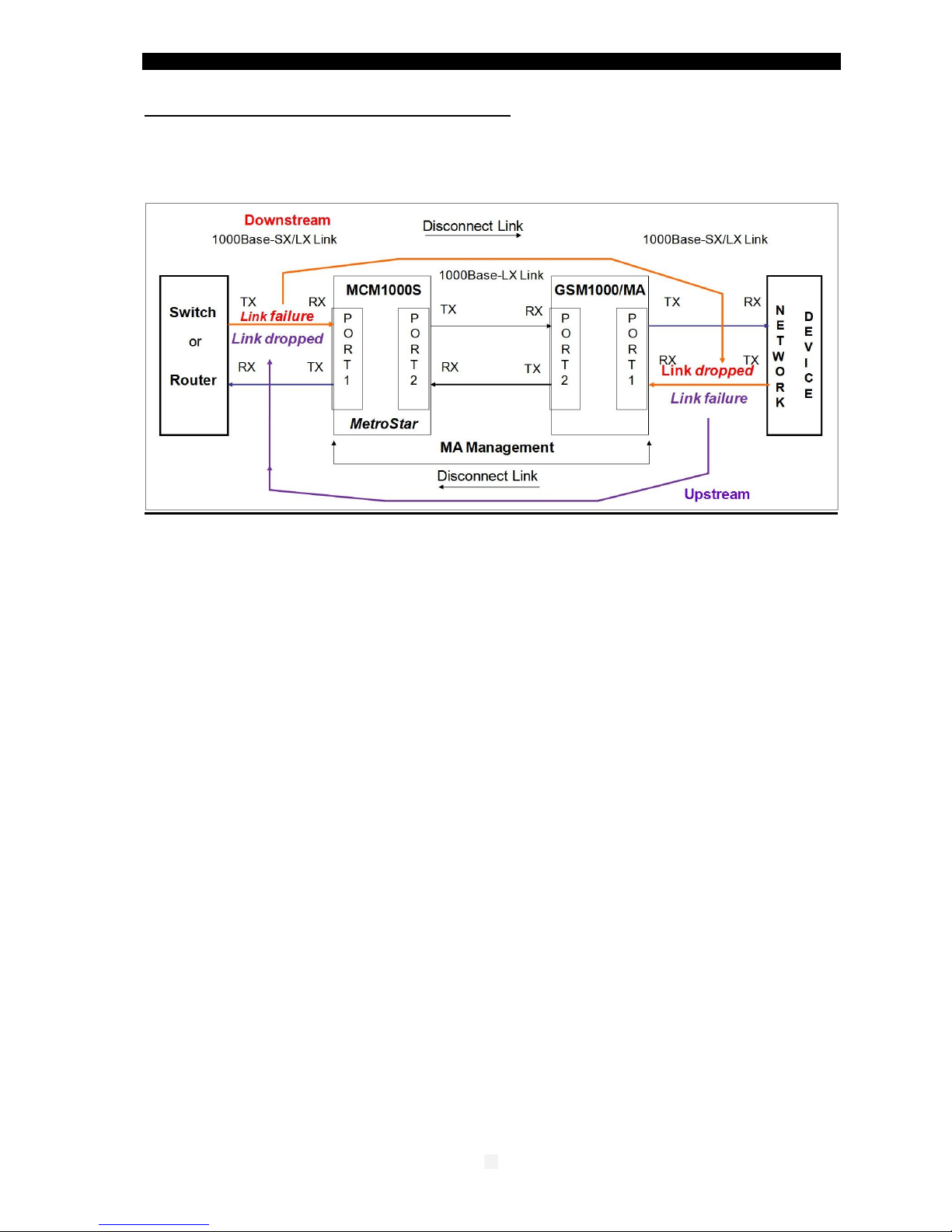
12 –SLE (Subscriber Link Emulation)
If the remote device is a FibroLAN MA™ device (GSM1000/MA or GSM1010/MA) and
the MetroStar system is managed, the most powerful SLE feature may be deployed to
further enhancing the network resilience.
SLE Operations
FibroLAN’s Subscriber Link Emulation virtually emulates the subscriber’s device or
network connected to the TP (or F/O) port of the remote device (GSM1010/MA or
GSM1000/MA) onto the F/O link of the MCM1000S/L port module (connected usually to
a switch/router). When activated (controllable via the management system only) it
senses the loss of the TP link (or F/O link) connected to the remote MA device, notifies
the MCM1000S/L and cuts off the port 1 F/O link of the MCM1000S module, alerting in
real time the switch/router of the subscriber’s failure. All this is performed without
disrupting the main F/O link, thus ensuring on-going control of the remote device (CPE)
via MA.
It should be noted that if the F/O link of port 1 of the MCM1000S/L module
(normally connected to a switch/router port) has failed, the SLE will cut-off the TP
port (or F/O) link of the remote GSM1000/MA device, providing in this manner an
optimal bidirectional safe operation.
Thus SLE has in effect two modes of operation:
Downstream SLE mode: link failure of the MCM1000S/L module F/O input port
(port 1) will cause the disconnect of the link input port of the remote GSM1000/MA
device
Upstream SLE mode: remote MA device link input port failure will cause the
disconnect of the MCM1000S module link port
Again it must be emphasized that this extensive set of features is obtained only if MA
enabled devices are installed at both ends of the link.
Note: When the SLE mechanism is enabled, it will override the LST mechanism.
During normal network operation, it is recommended to activate the SLE mechanism.
(Enable Downstream and Upstream modes through the management).
Use and stay in the LST ON (TEST mode) if link failure alertness is not needed.
In this case a link failure is indicated by its LED link OFF.

MCM1000S/L GBE module
07
13 –Typical Configuration
The MMM-01 Management module installed in the MetroStar System will monitor and
control and manage the modules installed in the MetroStar chassis and the remote MA devices.
It will report alerts and traps to the SNMP Manager located in the Central Node.
MetroStar™ equipped with a management module can be monitored and managed
from any SNMP management station running popular management platforms
(e.g. FibroLAN’s MetroView, HP OpenView, SNMPc, etc)
When the remote MA enabled devices are connected through their F/O link to a remote
Access Concentrator like the MetroStar which is MA™ enabled and SNMP managed, a
comprehensive set of monitoring and control functions can be implemented (through the
MCM1000S MA enabled module) into GSM1000 MA enabled remote devices.
When the remote device is not an MA device the MCM1000S/L module will act/perform as
a normal GBE media converter in respect to the attached remote device.

MCM1000S/L GBE module
08
14 –Troubleshooting
Prior to performing the following procedures, verify that the LB DIP switches are in DOWN
position (loop-back disable). Verify that the LST DIP switches are in Test Mode. Perform
the same setup at the remote MA device, including the disabling of SLE.
Problem
Indication
Corrective Action
No power
LED PWR:
Main power not
lit
Ascertain that the module is well inserted into its
slot and that its screws are firmly fastened.
Check that the power supplies LEDs in the PMM or
Management module are lit
Fiber link not working
(port 1 or port 2)
Link LED not lit
Verify that the correct fiber optic cables are being
used, i.e. multi-mode or single mode. Check that
the receive fiber is properly connected to the
transmit port of the remote fiber device AND the
transmit port to the receive port of the remote
device.
Perform a loop-back test to verify F/O port
integrity.
If LB test fails, verify that the output power of the
fiber optic port (s) is within manufacturer’s
specifications. Verify that the dB loss of the fiber
cable you are connecting to plus additional losses
(connectors losses, normally 1,5dB per mated pair;
Splice loss 0.3db max and 3db loss for safety
margin) is within the allowed dB budget. You may
deploy the LST ON to locate the failing segment
(Refer to section 11 for more details).
No transmit/receive on
F/O port
LED Act not lit
Check the status of the various LEDs indications
and F/O Links. Ensure that the equipment attached
to the MCM1000S module is properly configured
and operating.
Recall that the MCM1000S module does NOT
support Auto-Neg. on its F/O ports. Thus any
network device that is connected to the
MCM1000S F/O ports should be configured to
A/N disabled mode (i.e. forced to 1000Mbps and
FDX.
MA is not working
MA Active LED
not lit
Verify that the MCM1000S module is properly
connected to the remote MA device
Check that the Link LED is lit at both ends.
At the MetroStar management station perform the
following MCM1000S module checks:
a. Link status
b. Signal Detect status
If necessary, you may perform the “ Restore link
default parameters “ command
Check also the status of the remote attached
device.

MCM1000S/L GBE module
09
If the problem persists after carrying out the above procedure, do the following: exchange
suspected MCM1000S module with another similar module, and check connectivity
and mode of operation. If that has solved the problem, send your MCM1000S for repair. If
the problem still persists, there is probably some sort of general network failure. Call your
Make sure to provide the following information:
Date and place of purchase, from whom, original invoice
The serial number of the MCM1000S module and its Firmware revision
The serial # of the MetroStar™ including type of the installed modules.
The configuration of the equipment that is connected to the MetroStar™and the
sequence of events leading to the problem.
Actions already taken and status files.
Software revision levels of the installed equipment.
15 –Specifications
Standard Compliance
IEE 802.3 2000 edition, 1000Base-SX 1000Base-LX, IEEE802.3z
Conversion Method: Digital Conversion
Management:
SNMP management via MetroStar management module –MMM-01
F/O ports
Port 2: Duplex SC, S/M fiber, 1310/1550nm, 1000Base-LX (10/20/40/80/120 Km)
Port 1: Duplex SC, M/M fiber, 850nm, 1000Base-SX, (220m)
For Fiber optic specifications for each MCM1000S model, refer to “ section 7 “ Fiber Optic
Connections
Diagnostic LEDs:
Link, Activity (Tx or Rx), LB (loop-back), LST LEDs for F/O port 1
Link, Activity (Tx or Rx), LB (loop-back), LST LEDs for F/O port 2
MA Active (indicating MCM1000S connected to a remote MA active device) Common
LED
Power: power on / off (PWR LED)
DIP switches (mother board) per port
LST (Link Segmentation Test) Normal / Test mode (Down/Up)
LB (loop-back) enable / disable (Up/ Down)
The active Ma™ Management overrides the DIP switches setting
Management of Remote Devices: via MA™ Technology
SLE mechanism enabled/disabled thru MMM-01 management module
Specifications are subject to change without prior notice
Module default settings
Downstream bandwidth 1000Mbps
Channel enabled
LST enabled both ways (LST ON)
LB disabled both ways
SLE disabled both ways
No channel description

MCM1000S/L GBE module
21
16 –Warranty Limitation
FibroLAN warrants the equipment to be free from defects in material and workmanship, under
normal and proper use and in its unmodified condition for 24 months (unless
otherwise agreed upon) starting on the date of delivery from FibroLAN to its distributor.
FibroLAN’s sole obligation under this warranty shall be to furnish parts and labor for the repair or
replacement of products found by FibroLAN to be defective in material or workmanship during
the warranty period. Warranty repairs will be performed at the point of manufacture.
Following an authorized repair, the device shall be under warranty throughout its original period
but not less than 3 months.
Warranty shall be void in case where unauthorized attempts to repair or disassemble
/modify the device are evident.
You must claim repairs or replacements under this warranty only from the reseller from which you
have purchased the device, however you may refer directly to FibroLAN Ltd. to claim the
warranty providing reasonable proof that the reseller ceased operation and/or unreasonably
refused to provide you with the service. In such case you provide to FibroLAN the serial number
of the device, date purchased, full details of reseller from whom the device was purchase and a
copy of an invoice or another proof of the purchase.
This document and the information contained herein are proprietary to the manufacturer
and are furnished to the recipient for use in operating, maintaining and repairing
manufacturer equipment.
The information within may not be utilized for any purpose except as stated herein, and
may not be disclosed to third parties without the written permission from the
manufacturer. The manufacturer reserves the right to make changes to any technical
specifications in order to improve reliability, function and design.
This manual is applicable for Firmware revision v 2.3 and up
©COPYRIGHT 2003 –FibroLAN Ltd. All rights reserved
June 2011 –Version 2.4
This manual suits for next models
13
Table of contents
Other FibroLAN Media Converter manuals


Popular Media Converter manuals by other brands

Baumer
Baumer Hubner DeviceNet HMG10 operating manual

ADF Web
ADF Web HD67E05-IP-A1 user manual

Aventura
Aventura FBR-1FE1FX-SFP-MINI instruction manual

Adaptec
Adaptec VideOh! CD AVC-1100 Getting started

FOLSOM
FOLSOM 2100DE Installation and operator's manual

Shenzhen 3onedata Technology
Shenzhen 3onedata Technology 3012 user manual


Transition Networks
Transition Networks C4TEF1011-110 user guide

Cypress
Cypress HTCP-255DN Operation manual

NXP Semiconductors
NXP Semiconductors SSL2101 user manual

Treasure Cove
Treasure Cove Vibra-Phone 280 manual

Hama
Hama 00039960 operating instructions

Taiden
Taiden HCS-8316 series Installation and operation manual