Microelettrica Scientifica MG30 User manual

Doc. N° DB-0084
DATA BASE
MG30 Rev. 0
Pag. 1 of 11
Copyright 1999 Microelettrica Scientifica
MULTIFUNCTION GENERATOR
PROTECTION RELAY
TYPE
MG30
OPERATION MANUAL

Doc. N° DB-0084
DATA BASE
MG30 Rev. 0
Pag. 2 of 11
Copyright 1999 Microelettrica Scientifica
1 - Supported MODBUS functions.
Both the communication ports support the following MODBUS RTU commands:
- Read N words (codes 3 and 4).
- Write N words (code 16).
Warning: the ‘Write N words’ command is limited to 4 words per message (due to internal memory
limitations)
2 - Latency time.
Latency time is the time taken by a synchronization message to reach destination. Such time (and
generally speaking all known delays) can be automatically compensated by the unit. A special setting
(TLat) is available for such purpose. TLat is added to the current time when a synchronization message
is received.
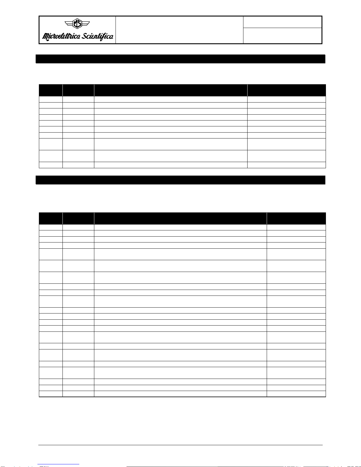
3 - ACTUAL MEASUREMENTS
All the following words are READ ONLY
Word
Number Name Meaning Notes
1 IA Phase A current Unit = A
2 IB Phase B current Unit = A
3 IC Phase C current Unit = A
8ϕA Phase displacement of IA on EA Unit = deg
Min = 0,
Max =359
(360 => no angle measurement)
9ϕB Phase displacement of IB on EB As above
10 ϕC Phase displacement of IC on EC As above
12 T/TnActual thermal status Unit = %Tn
14 I2Negative sequence current % Ib
15 f System frequency Unit = 0.01Hz
7001 = overflow
16 UAB Phase A to phase B voltage Unit = %Un
17 UBC Phase B to phase C voltage Unit = %Un
18 UCA Phase C to phase A voltage Unit = %Un
19 Uo 0 sequence voltage Unit = %Un
20 EA Phase A to neutral voltage Unit = %En
21 EB Phase B to neutral voltage Unit = %En
22 EC Phase C to neutral voltage Unit = %En
29 W Three phase active power Unit = %Wb
sign = 3° bit word 37
801 = overflow
65000 = dis
37.3 Sign of W Sign of three phase active power 0 !+
1 !-
37.7 Sign of Q Sign of three phase reactive power 0 !+
1 !-
52 Q Three phase reactive power Unit = %Wb
sign = 7° bit word 37
801 = overflow
65000 = dis
61 C_T_1
Current time: Years (format: 00YY (BCD)) Note 1
62 C_T_2 Current time: Months, Days (format: MMDD (BCD)) Note 1
63 C_T_3 Current time: Hours, Minutes (format: HHMM (BCD)) Note 1
64 C_T_4 Current time: Seconds, Hundredths of second (format: SSTT
(BCD)) Note 1
87 Un3 3th harmonic 0 sequence voltage %Un
Doc. N° DB-0084
DATA BASE
MG30 Rev. 0
Pag. 3 of 11
Copyright 1999 Microelettrica Scientifica
4 - MAXIMUM VALUES
All the following words are READ ONLY
Word
Number Name Meaning Notes
1000 IA Max. phase A current Unit = 0.1In
1001 IB Max. phase B current Unit = 0.1In
1002 IC Max. phase C current Unit = 0.1In
1005 Uo 0 sequence voltage Unit = %Un
1006 T/Tn Max. thermal status Unit = %Tn
1008 I2Max. Negative sequence current Unit = %Ib
1017 IrMax. reverse current Unit = 0.1 %Ir
1018 W Max. three phase active power Unit = %Wb
801 = overflow
1052 Q Max. three phase reactive power Unit = %Wb
801 = overflow
1103 U03 Max. 3th harmonic 0 sequence voltage Unit = %Un
5 - LAST TRIP
All the following words are READ ONLY.
See note 2 for trip selection.
Word
Number Name Meaning Notes
2000 Cause Trip cause Note 4
2001 IA Phase A current 0.1In
2002 IB Phase B current 0.1In
2003 IC Phase C current 0.1In
2009 ϕAPhase displacement of IA on EA Deg
360 = overflow
2010 ϕBPhase displacement of IB on EB Deg
360 = overflow
2011 ϕCPhase displacement of IC on EC Deg
360 = overflow
2013 I2Negative sequence current %Ib
2014 T/TnThermal status %Tn
2015 f System frequency 0.01Hz
7001 = overflow
2019 U0 0 sequence voltage %Un
2020 EA Phase A to neutral voltage %En
2021 EB Phase B to neutral voltage %En
2022 EC Phase C to neutral voltage %En
2050 W Three phase active power %Wb
801 = overflow
2150 IrReverse current %Ir
2151 Q Three phase reactive power %Wb
801 = overflow
2152 Uo3 3th harmonic 0 sequence voltage %Un
2360 LT_T_1
Trip time: Years (format: 00YY (BCD)) Note 1
2361 LT_T_2 Trip time: Months, Days (format: MMDD (BCD)) Note 1
2362 LT_T_3 Trip time: Hours, Minutes (format: HHMM (BCD)) Note 1
2363 LT_T_4 Trip time: Seconds, Hundredths of second (format: SSTT (BCD)) Note 1
Doc. N° DB-0084
DATA BASE
MG30 Rev. 0
Pag. 4 of 11
Copyright 1999 Microelettrica Scientifica
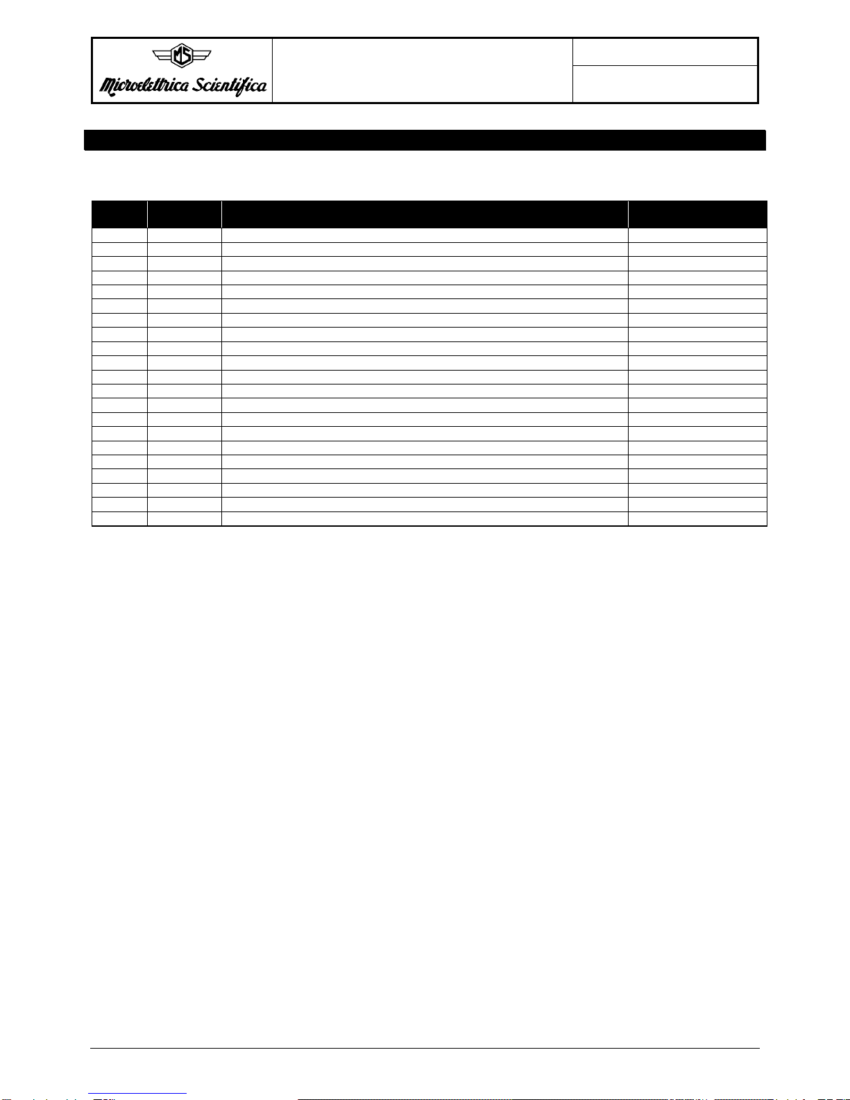
6 - TRIP NUMBER
All the following words are READ ONLY.
Word
Number Name Meaning Notes
3000 I > Trips number I > //
3001 I >> Trips number I >> //
3010 T > Trips number T > //
3016 1f Trips number 1f //
3017 2f Trips number 2f //
3018 1u Trips number 1u //
3019 2u Trips number 2u //
3020 Uo> Trips number Uo> //
3021 Uo>> Trips number Uo>> //
3024 Flux> Trips number Flux> //
3025 Flux>> Trips number Flux>> //
3026 1IsTrips number 1Is//
3027 2IsTrips number 2Is//
3041 Ir> Trips number Ir> //
3042 Z< Trips number Z< //
3068 W < Trip number W < //
3069 Z < Trips number Z < //
3070 Z< < Trips number Z< < //
3071 F60FL Trips number F60FL //
3072 F50/27 Trips number F50/27 //
3073 Un3< Trips number F64S100 //
Doc. N° DB-0084
DATA BASE
MG30 Rev. 0
Pag. 5 of 11
Copyright 1999 Microelettrica Scientifica
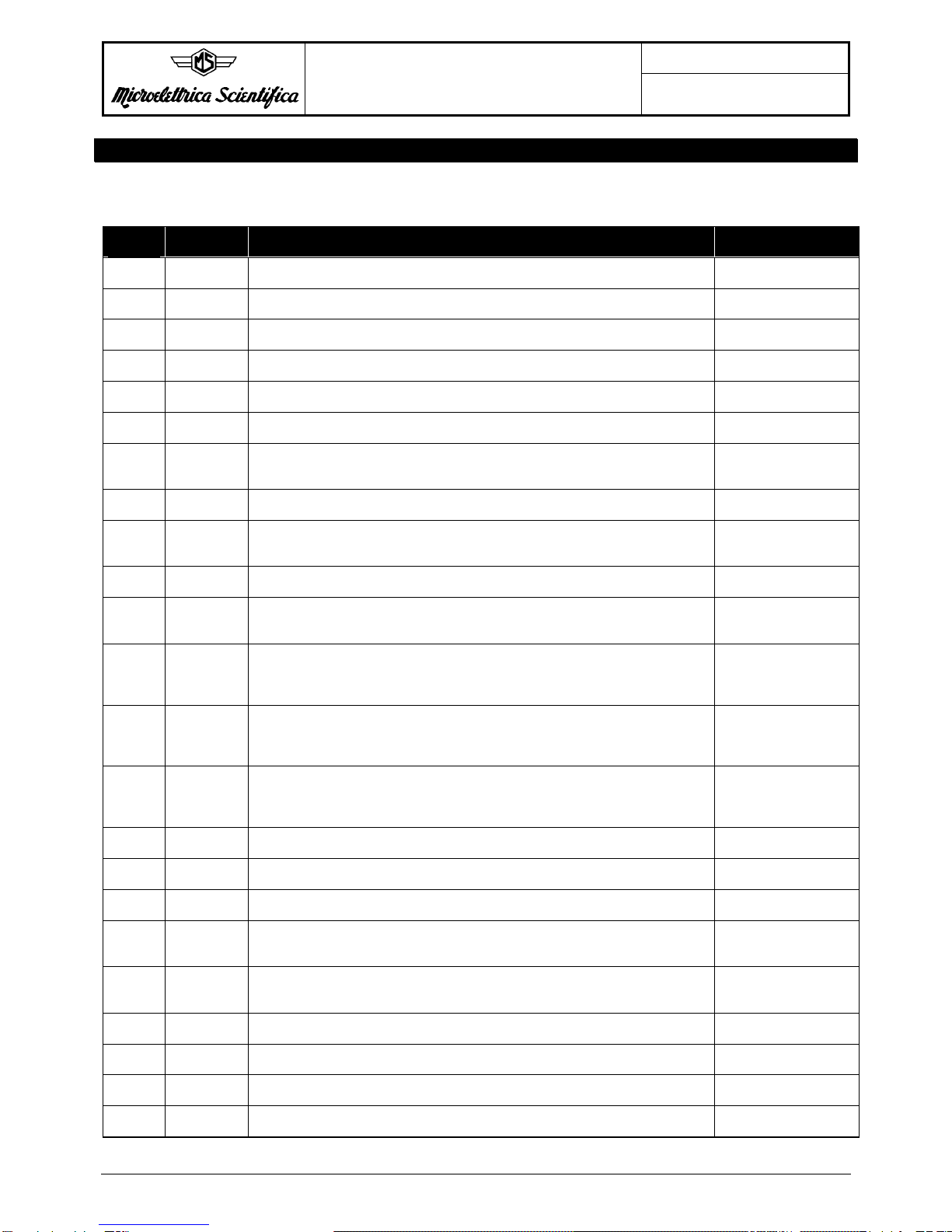
7 - SETTINGS
All the following words can always be read. To write them the user must first write a password (2295)
into word 8001. Such password is valid for 30s.
Word
Number Name Meaning Notes
5000 Nodad Id number for connection on serial comm. bus Min = 1,
Max = 250
5001 Fn Mains frequency 0 => 50Hz
1 => 60Hz
5002 In Rated primary current of phase C.T.s Unit = A
Min = 0, Max = 9999
5005 UnS P.T. rated secondary phase to phase voltage Unit = V
Min = 50, Max = 125
5006 Ib Generator’s rated current as pu of C.Ts rated current Unit = 0.1In
Min = 5, Max = 11
5008 F(I>) Operation characteristic of low-set overcurrent element 0 => D
1 => SI
5009 I > Trip level of low set overcurrent element Unit = 0.01 Ib
Min = 100, Max = 250
I> = 251 !Dis
5010 tI> Trip time delay of low set overcurrent element Unit = 0.01s
Min = 5, Max = 3000
5011 I >> Trip level of high set overcurrent element Unit = 0.1Ib
Min = 10, Max = 99
I>> = 100 => Dis
5012 tI>> Trip time delay of high set overcurrent element Unit = 0.01s
Min = 5, Max = 300
5020 tBF Max. reset time delay of the instantaneous elements after tripping of the
delayed elements and time delay for the activation of the output relay
associated to the Breaker Failure function
Unit = 0.01s
Min = 5, Max = 50
5021 t2 = The operation of the blocking input (2) can be programmed so that it lasts as
long as the blocking input signal is present (t2 = OFF) or so that, even with the
blocking input still present, it only lasts for the set trip timedelay of the function
plus an additional time 2xtBF (t2 = 2xtBF)
0 => OFF
1 => 2xtBF
5023 2A The input (2) for blocking the time delayed elements relevant to phase
operates on (I>) or (I>>) or (I> + I>>) 0 => None
1 => I>>
2 => I> + I>>
3 => I>
5024 3A The blocking input (3) operates on function F40 or Ir> or F40 + Ir > 0 => None
1 => Ir
2 => LF
3 => Ir+LF
5025 tFRes Auto/Manual reset of output relays 0 => M
1 => A
5029 Tc Thermal time constant of the alternator Unit = min
Min = 1, Max = 400
5031 Ta/n Prealarm level of thermal image Unit = %Tn
Min = 50, Max = 110
5035 1Is Generator’s max. continuous negative sequence current Unit = 0.01 Ib
Min = 5, Max = 50
1Is = 51 => Dis
5037 2Is Negative sequence current alarm level Unit = 0.01 Ib
Min = 3, Max = 50
2Is = 51 => Dis
5038 t2Is Independent trip time delayed of alarm element Unit = s
Min = 1, Max = 100
5039 Ks Time multiplier of the I2t time-current curve Unit = s
Min = 5, Max = 80
5040 tcs Cooling time from trip level to the state corresponding to I2 = 1Is Unit = s
Min = 10, Max = 1800
5048 I >/U Voltage control on level I > 0 => OFF
1 => ON

Doc. N° DB-0084
DATA BASE
MG30 Rev. 0
Pag. 6 of 11
Copyright 1999 Microelettrica Scientifica
Word
Number Name Meaning Notes
5049 I >>/U Voltage control on level I >> 0 => OFF
1 => ON
5051 14A The blocking input (4) (terminals 1-14) blocks the operation of the functions
1f, or 2f or 1f+2f 0 => None
1 => 1f
2 => 2f
3 => 1f + 2f
5052 14B The blocking input (4) (terminals 1-14) blocks the operation of the functions
1u, or 2u or 1u+2u 0 => None
1 => 1u
2 => 2u
3 => 1u + 2u
5053 2B The blocking input (2) (terminals 1-2) blocks the operation of the functions
Z>, or Z>> or Z>+Z>> 0 => None
1 => 1Z (Z<)
2 => 2Z (Z<<)
3 => 1Z (Z<) + 2Z
(Z<<)
5054 3B The blocking input (3) (terminals 1-3) blocks the operation of any combination
of the functions 1N, 2N, N3 0 => None
1 => 1N
2 => 2N
3 => 1N + 2N
4 => N3
5 => 1N3 N3
6 => 2N N3
7 => 1N2NN3
5055 Vs Rated secondary voltage of the earth fault Vt Unit = V
Min = 50, Max = 125
5061 Un +/-1u Operation mode of first voltage element 0 => -
1 => +
2 => +/-
3 => Dis
5062 1u Pick-up level of first voltage element Unit = %Un
Min = 5, Max = 50
5063 t1u Trip time delay of the first voltage element Unit = 0.1s
Min = 1, Max = 600
5064 Un +/-2u Operation mode of second voltage element 0 => -
1 => +
2 => +/-
3 => Dis
5065 2u Pick-up level of second voltage element Unit = %Un
Min = 5
Max = 50
5066 t2u Trip time delay of the second voltage element Unit = 0.1s
Min = 1, Max = 600
5074 Uo> 0 sequence voltage first threshold Unit = 0.01 Un
Min = 5, Max = 99
Uo> = 100 => Dis
5075 tUo> 0 sequence voltage first threshold Unit = 0.01 sec
Min = 5, Max = 999
tUo> = 4 => Ist.
5076 Uo>> 0 sequence voltage second threshold Unit = 0.01 Un
Min = 5, Max = 99
Uo> = 100 => Dis
5081 tφ>> Time delay (definite time) of the 2 V/Hz element Unit = 0.1 sec
Min = 1, Max = 600
5082 Fn +/- 1f Operation mode of first frequency element 0 => -
1 => +
2 => +/-
3 => Dis
5083 1f Pick-up level of first frequency element Unit = 0.01Hz
Min = 5, Max = 999
5084 t1f Trip time delay of first frequency element Unit = 0.1s
Min = 1, Max = 600

Doc. N° DB-0084
DATA BASE
MG30 Rev. 0
Pag. 7 of 11
Copyright 1999 Microelettrica Scientifica
Word
Number Name Meaning Notes
5085 Fn +/-2f Operation mode of second frequency element 0 => -
1 => +
2 => +/-
3 => Dis
5086 2f Pick-up level of second frequency element Unit = 0.01Hz
Min = 5
Max = 999
5087 t2f Trip time delay of second frequency element Unit = 0.1s
Min = 1, Max = 600
5099 tz Trip time delay of the underimpedance element Unit = 0.1s
Min = 2, Max = 600
5100 ti Integration time of underimpedance element Unit = 0.1s
Min = 0, Max = 100
5101 K1 Diameter of the circle including the underimpedance tripping zone Unit = %Zb
Min = 50, Max = 300
K1 = 301 !Dis
5102 K2 Offset of the circle Unit = %Zb
Min = 5, Max = 50
5103 Ir > Trip level of the reverse power element Unit = 0.01Ib
Min = 2, Max = 20
Ir> = 21 => Dis
5104 tIr Independent trip time delay of reverse power element Unit = 0.01s
Min = 10, Max = 6000
5105 W< Pick-up level of the active underpower element Unit = 0.01Wb
Min = 5, Max = 100
W< = 4 !Dis
5106 tW< Trip time delay of the active underpower element Unit = 0.1s
Min = 1, Max = 600
5119 Tsyn Sync time 0 => 5min.
1 => 10min.
2 => 15min.
3 => 30min.
4 => 60min.
5 => Dis.
5120 Time0 Current time : Years
BCD format (00YY) Note 1
5121 Time1 Current time Months/Days, BCD format (MMDD) Note 1
5122 Time2 Current time: Hours/Minutes, BCD format (HHMM) Note 1
5123 Time3 Current time: Seconds/10ths of a second, BCD format (SSTT) Note 1
5185 1Z Minimum impedance first threshold Unit = 0.01Zn
Min = 10, Max = 100
Z< = 9 => Dis
5186 t1Z Minimum impedance first threshold time delay Unit = 0.01sec
Min = 5, Max = 999
tZ< = 4 => Ist.
5187 2Z Minimum impedance second threshold Unit = 0.01Zn
Min = 10, Max = 100
Z<< = 9 => Dis
5188 t2Z Minimum impedance second threshold time delay Unit = 0.01sec
Min = 5, Max = 999
tZ<< = 4 => Ist.
5189 ENF60FL Enable/disable F60FL (TV fuse failure) 0 => OFF
1 => ON
5190 IC Enable/Disable IC 0 => OFF
1 => ON
5191 Uo3 Earth fault 100% threshold Unit = %On
Min = 1, Max = 30
Uo3 = 0 => Dis
5192 tUo3 Earth fault 100% time delay Unit = 0.01 sec
Min = 5, Max = 999
tUo3 = 4 => Ist
5193 Kv External PTs ratio Unit = 0.1
Min = 20, Max = 6550
Doc. N° DB-0084
DATA BASE
MG30 Rev. 0
Pag. 8 of 11
Copyright 1999 Microelettrica Scientifica
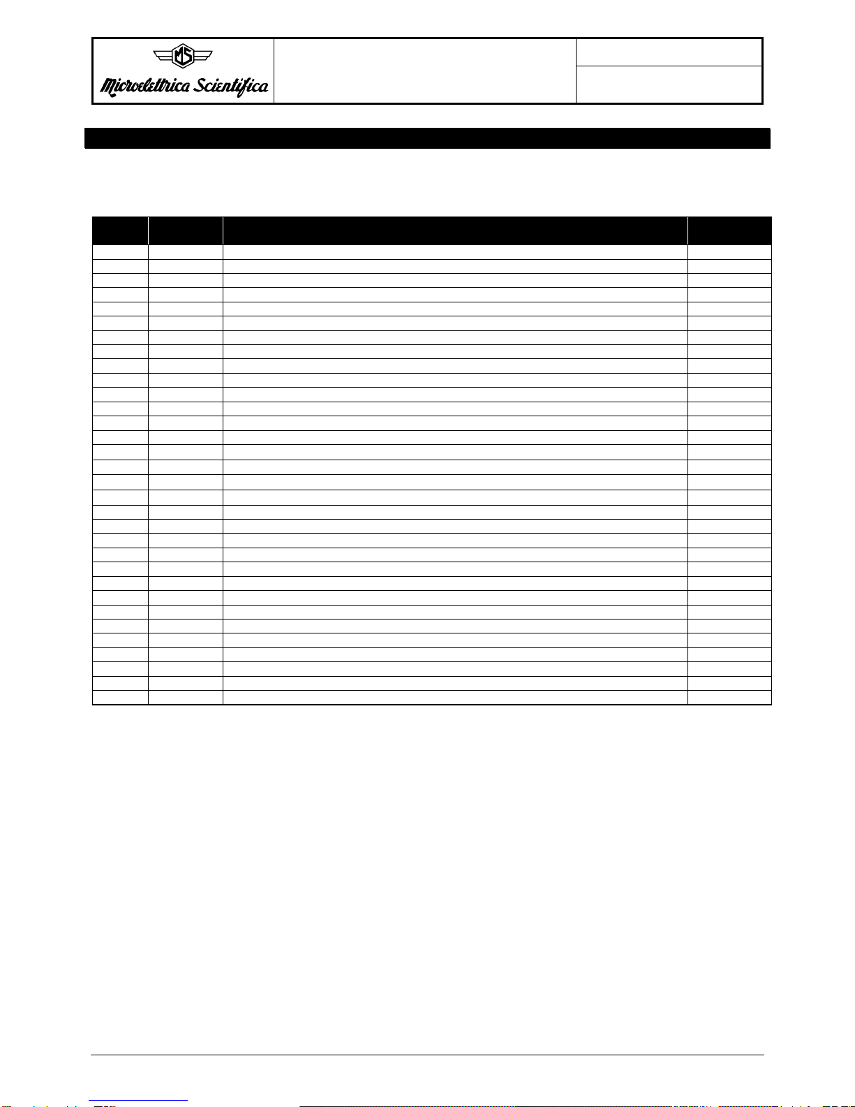
8 - F->RELAY
All the following words can always be read. To write them the user must first write a password (2295)
into word 8001. Such password is valid for 30s.
Word
Number Name Meaning Notes
6000 I> Inst element of low set overcurrent operates relays R1, R2, R3, R4 Note 3
6001 tI> As above, time delayed element Note 3
6002 I>> Inst element of high set overcurrent operates relays R1, R2, R3, R4 Note 3
6003 tI>> As above, time delayed element Note 3
6008 T > Overtemperature element operates relays R1, R2, R3, R4 Note 3
6009 Ta > Thermal prealarm element operates relays R1, R2, R3, R4 Note 3
6011 1Is First unbalance element (time delayed) operates relays R1, R2, R3, R4 Note 3
6012 2Is As above, second unbalance element Note 3
6017 1U First voltage element (time delayed) operates relays R1, R2, R3, R4 Note 3
6019 2U Second voltage element (time delayed) operates relays R1, R2, R3, R4 Note 3
6025 Uo> First 0 sequence voltage element (inst.) operates relays R1, R2, R3, R4 Note 3
6026 tUo> First 0 sequence voltage element (time delayed) operates relays R1, R2, R3, R4 Note 3
6027 Uo>> Second 0 sequence voltage element (inst.) operates relays R1, R2, R3, R4 Note 3
6028 tUo>> Second 0 sequence voltage element (time delayed) operates relays R1, R2, R3, R4 Note 3
6029 φ> First V/Hz element (inst.) operates relays R1, R2, R3, R4 Note 3
6030 tφ> First V/Hz element (time delayed) operates relays R1, R2, R3, R4 Note 3
6031 φ>> Second V/Hz element (inst.) operates relays R1, R2, R3, R4 Note 3
6032 tφ>> Second V/Hz element (time delayed) operates relays R1, R2, R3, R4 Note 3
6034 1f First frequency element (time delayed) operates relays R1, R2, R3, R4 Note 3
6036 2f Second frequency element (time delayed) operates relays R1, R2, R3, R4 Note 3
6043 F40 F40 element operates relays R1, R2, R3, R4 Note 3
6044 tIr > Reverse power time delayed element operates relays R1, R2, R3, R4 Note 3
6045 tW < Underpower time delayed element operates relays R1, R2, R3, R4 Note 3
6074 tBF Breaker Failure function operates relays R1, R2, R3, R4 Note 3
6075 F60FL F60FL element operates relays R1, R2, R3, R4 Note 3
6076 F50/27 > Reverse power time delayed element operates relays R1, R2, R3, R4 Note 3
6077 tZ < Minimum impedence first delayed element operates relays R1, R2, R3, R4 Note 3
6078 tZ << Minimum impedence second delayed element operates relays R1, R2, R3, R4 Note 3
6079 tUo3< 3td harmonic 0 sequence voltage delayed element operates relays R1, R2, R3, R4 Note 3
6095 Z < Minimum impedence first inst. element operates relays R1, R2, R3, R4 Note 3
6096 Z << Minimum impedence second inst. element operates relays R1, R2, R3, R4 Note 3
6097 Uo3< 3td harmonic 0 sequence voltage inst. element operates relays R1, R2, R3, R4 Note 3

Doc. N° DB-0084
DATA BASE
MG30 Rev. 0
Pag. 9 of 11
Copyright 1999 Microelettrica Scientifica
9 - TRIP STATUS
All the following bits are read only
Word
Number Name Meaning Notes
7000.0 I > I> trip status 0 => No trip
1 => Trip
7000.1 tI > tI> trip status As above
7000.2 I >> I>> trip status As above
7000.3 tI >> t>> trip status As above
7000.8 T> T>ip status As above
7000.10 Ta Ta trip status As above
7000.12 1Is 1Is trip status As above
7000.13 t1Is t1Is trip status As above
7000.14 2Is 2Is trip status As above
7000.15 t2Is t2Is trip status As above
7001.4 1u 1u trip status As above
7001.5 t1u t1u trip status As above
7001.6 2u 2u trip status As above
7001.7 t2u t2u trip status As above
7001.13 Uo> Uo> trip status As above
7001.14 tUo> tUo> trip status As above
7001.15 Uo>> Uo>> trip status As above
7002.0 tUo>> tUo>> trip status As above
7002.1 1φtrip status As above
7002.2 t1φtrip status As above
7002.3 2φtrip status As above
7002.4 t2φtrip status As above
7002.5 1f 1f trip status As above
7002.6 t1f t1f trip status As above
7002.7 2f 2f trip status As above
7002.8 t2f t2f trip status As above
7002.15 F40 F40 trip status As above
7003.0 tF40 tF40 trip status As above
7003.1 Ir > Ir> trip status As above
7003.2 tIr > tIr> trip status As above
7003.3 W < W< trip status As above
7003.4 tW< tW< trip status As above
7006.0 F60FL Fuse fail element trip status As above
7006.1 F5027 As above
7006.2 Z< Z< trip status As above
7006.3 tZ< tZ< trip status As above
7006.4 Z<< Z<< trip status As above
7006.5 tZ<< tZ<< trip status As above
7006.6 Uo3 Uo3 trip status As above
7006.7 tUo3 tUo3 trip status As above
Doc. N° DB-0084
DATA BASE
MG30 Rev. 0
Pag. 10 of 11
Copyright 1999 Microelettrica Scientifica
10 - DIGITAL INPUTS STATUS
The following bits are read only
Word
Number Name Meaning Notes
7500.0 2__STATUS Status of input B2 0 !open
1 !closed
7500.1 3_STATUS Status of input B3 0 !open
1 !closed
7500.2 4_STATUS Status of input B4 0 !open
1 !closed
11 – COMMANDS
The following word is write only
Word
Number Name Meaning Notes
8000 CMD Remote commands Commands are encoded as follows:
0 => no command
1 => Test W/O trip
2 => Test W trip
3 => Reset
4 to 8 => Ignored
9 => Time sync
12 - PASSWORD
The following word is write only. When the value 2295 (decimal) is entered, settings and
F->relays can be modified for 30s
Word
Number Name Meaning Notes
8001 PWD Password -
13 - TRIP SELECTION WORD
This word is write only and works as a trip data selector. See note 2 for more details.
Word
Number Name Meaning Notes
8003 TRP_SEL Trip selector Min = 0, Max = 4
14 - DIAGNOSTIC STATUS
The following bits are read only. Bits can’t be individually addressed. The notation xxxx.yy means bit yy
of word xxxx. Bit 0 is the LEAST significant one.
Word
Number Name Meaning Notes
9000.0 ALU_FLT C.P.U. ALU fault 1 => fault 0 => no fault
9000.1 ADC_FLT Analog to Digital Converter fault 1 => fault 0 => no fault
9000.2 E2P_FLT Non volatile memory fault 1 => fault 0 => no fault
9000.4 KBD_FLT Keyboard fault (stuck key) 1 => fault 0 => no fault
9000.8 IRF Internal fault (generic) 1 => fault 0 => no fault
9000.9 PRG Programming 1 => relay is in PROG mode
0 => relay is not in PROG mode
9000.10 BRF Breaker failure 1 => breaker failure
0 => no breaker failure

Doc. N° DB-0084
DATA BASE
MG30 Rev. 0
Pag. 11 of 11
Copyright 1999 Microelettrica Scientifica
15 - RELAY ID
This word allows the host P.C. to identify the type of relay.
Word
Number Name Meaning Notes
64647 REL_ID Id of MG30 2.00 Value = 62
Notes
1) Date/time is expressed using 4 words containing BCD (Binary Coded Decimal) numbers. Each nibble
represents a digit. The first word stores Years (in a 2 digits format), the second one Months and
Days, the third one Hours and Minutes and the fourth one Seconds and Tenths of a second.
2) The MG 30 saves in memory the measured values during the 5 last trips.The word #8003 allows to
select the Active Last Trip. The values returned reading the addresses specified in the Last Trip
paragraph refer to the Active Last Trip. Write 0 in the word #8003 to select the Last Trip, write 1 to
select the Last Trip –1 and so on.
3) F => relays words are encoded as follows: each element has its own F => relays word, whose bits 0,
1, 2, 3 respectively corresponds to output relays R4, R3, R2, R1. Bits 4..15 are ignored by the unit.
So for example if IG_REL is equal to 7, it means that relays R2, R3 and R4 will be energised as soon
as the instantaneous low-set overcurrent element trips.
4) Trip causes are coded as follows:
Code Cause
0 Notrip
1 I>
2 I>>
3 1Is
4 2Is
5 Ir>
6 FL
7 1U
8 2U
9 1f
10 2f
11 W<
12 T>
13 1Z
14 2Z
15 1flux
16 2flux
17 1Uo
18 2Uo
19 Uo3
20 60FL
21 IC
Table of contents
Popular Other manuals by other brands

Siemens
Siemens Simatic RF600 System manual

NEC
NEC NEC020511 Applications

Digital Watchdog
Digital Watchdog CP-01 instruction manual

Richard Paul Russell
Richard Paul Russell SpaceLogger D10 user manual

Orbinox
Orbinox RR Flap Gate Installation, operation and maintenance manual

Aim
Aim MXS 1.2 Strada user guide


Elenco Electronics
Elenco Electronics MM-8000 user guide

PowerAid
PowerAid 300-563 Installation instructions manual

Trebs
Trebs Comfortheat 99286 manual

Zuwa
Zuwa DESCAL NIROSTAR 2000-A Original operating instructions

Sonnax Industries, Inc.
Sonnax Industries, Inc. Ford 4R44E ZIP KIT Installation & Testing Booklet

Eaton
Eaton EAFR-110 Series user manual