manuals.online logo
Brands
  1. Home
  2. •
  3. Brands
  4. •
  5. PowerAid
  6. •
  7. Other
  8. •
  9. PowerAid 300-563 Service manual

PowerAid 300-563 Service manual

Popular Other manuals by other brands

Opticon EduMic Compatibility guide

Opticon

Opticon EduMic Compatibility guide

Kessil A360W owner's manual

Kessil

Kessil A360W owner's manual

TEFAL ULTRA COMPACT MIXER manual

TEFAL

TEFAL ULTRA COMPACT MIXER manual

Martin Audio WS18X - SCHEMATICS manual

Martin Audio

Martin Audio WS18X - SCHEMATICS manual

Hendrickson AR2 series Service instructions

Hendrickson

Hendrickson AR2 series Service instructions

GO Industries 38017 installation instructions

GO Industries

GO Industries 38017 installation instructions

Cissell 30LBCMAN2 manual

Cissell

Cissell 30LBCMAN2 manual

RIDGID K-60SP manual

RIDGID

RIDGID K-60SP manual

Gage Bilt GB751SH-5 Original instructions

Gage Bilt

Gage Bilt GB751SH-5 Original instructions

OVE SIERRA 60 installation manual

OVE

OVE SIERRA 60 installation manual

ReelCraft 7800 OLB21 operating instructions

ReelCraft

ReelCraft 7800 OLB21 operating instructions

Body Armor 4x4 ECO-SERIES user manual

Body Armor 4x4

Body Armor 4x4 ECO-SERIES user manual

ROBLIN DROP Dimensions

ROBLIN

ROBLIN DROP Dimensions

EMG EMG-ACB BARREL Installation information

EMG

EMG EMG-ACB BARREL Installation information

MiniSolar MT-150 Assembling Guide

MiniSolar

MiniSolar MT-150 Assembling Guide

Parkside PSZ 250 B2 Operation and safety notes

Parkside

Parkside PSZ 250 B2 Operation and safety notes

ABB REM 610 Technical reference manual

ABB

ABB REM 610 Technical reference manual

Tyent ACE-13 user manual

Tyent

Tyent ACE-13 user manual

manuals.online logo
manuals.online logoBrands
  • About & Mission
  • Contact us
  • Privacy Policy
  • Terms and Conditions

Copyright 2025 Manuals.Online. All Rights Reserved.

1
# 300-563 INSTALLATION INSTRUCTIONS
02-04 Dodge Ram 3.7L
Parts List
AIR-KIT563PA Aluminum Plate (1)
AIR-KIT563H Hardware
“O” ring (1)
6mm x 50mm Hex Head Bolts (3)
6mm Flat Washers (3)
1/2”Extension Plate (1)
1” Extension Plate (1)
6mm x 20mm Flat Head Screw (1)
6mm x 35mm Flat Head Screw (1)
1/4”ID x 3/4”OD x 5/8”OAL (1)
Air Box Flange Nut (1)
Air Box Support Plate (1)
5/16” x 1 1/2” Flat Head Screw (1)
Throttle Cable Bracket (1)
3/8”ID x 3/4”OD x .636 OAL (2)
Nutplate w/ 3/8-16” threads (1)
3/8-16” x 1 1/2” Hex Head Bolts (2)
Tools List
1/4” Ratchet
1/4” x 12” Extension
8mm Socket
10mm Socket
14mm Socket
Thank you for purchasing the PowerAid Throttle Body Spacer. Please read the
instruction manual carefully before proceeding with the installation. Your PowerAid
Throttle Body Spacer was carefully inspected and packaged. Check that no parts are
missing, or were damaged during shipping. If you need any assistance please call 1-
800-858-3333 to speak with a representative in our Customer Service Center before
returning the product. Thank you for selecting AIRAID.
Included with your Poweraid Spacer is a
sticker with a California Air Resources
Board (C.A.R.B.) Executive Order
(EO) number. This sticker must be
placed in plain view inside of the engine
compartment. Failure to do so may pre-
vent you from passing a smog inspec-
tion.
INTAKE SYSTEMS FOR VEHICLES LISTED ARE 50 STATE
LEGAL. SEE AIRAID.COM FOR CARB STATUS ON EACH
PART FOR A SPECFIC VEHICLE.
2
Installation Instructions. Read Me!
1. DISCONNECT NEGATIVE (-) BATTERY CABLE.
2. Remove air intake hose assembly.
3. Remove throttle body air intake box and save bolts.
4. Remove (3) bolts from the throttle body.
5. Unclip throttle & cruise cables and remove from manifold and throttle lever.
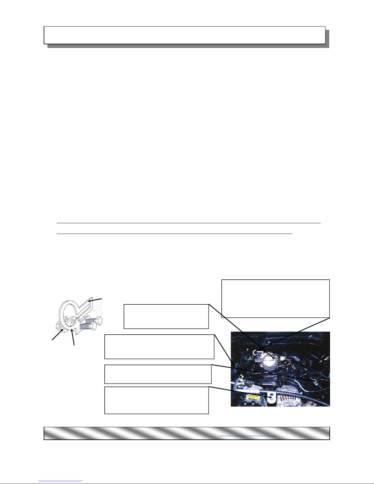
6. Install power plate using (3) 6mm x 50mm bolts and 6mm flat washers. (Ref. “A”)
7. Install throttle & cruise cable bracket and tighten bolts. (Ref. “B”)
8. Install both throttle & cruise cables thru reinforcement ring of throttle cable bracket.
A. Reattach cables to throttle body lever. *First cruise cable then throttle cable
B. Slide and lock both plastic cable retainers into slot separately.
9. Locate (1) long extension plate using (1) flat head screw to reposition throttle body intake box using saved
bolts (Ref. “D” and Step 3)
10. Locate (1) short extension plate with 5/8” thick spacer using (1) flat head screw to reposition throttle body
intake box using saved bolts. (Ref. “C” and Step 3)
11. Install air box support bracket using (1) flat head screw & (1) flange nut. (Ref. “E”)
12. Inspect & Test throttle linkage for full Open & Closed travel before driving. Some cruise and kick down ca-
bles may require adjustment. Please refer to your vehicles service manual for proper adjustment.
13. Reinstall throttle body air intake assembly using (Step2) as an example.
14. Reconnect battery cable. Enjoy!
The sound of power...The “whistle” means its working!
ASSEMBLY DETAIL (Ref. “B”)
Bracket
(2) Spacers
Nut-
Ref. “A”- (1) Power Plate
(1) “O” ring
(3) 6mm x 50mm Bolts
Ref. “B”- (1) Throttle Cable Bracket
(2) .636 long w/ 3/8” hole spacers
(2) 3/8-16” x 1 1/2” bolts
(1) Nutplate
Ref. “C”- (1) 1/2” Extension Plate
(1) 6mm x 34mm Flat head screw
(1) 5/8” w/ 1/4” hole spacer
Ref. “D”- (1) 1” Extension Plate
(1) 6mm x 20mm Flat head screw
Ref. “E”- (1) Air box flange nut
(1) Air box support plate
(1) 5/16” x 1 1/2” flat head screw
AIR-I30563B
Rev. 12.21.16
Airaid. 1815 West Crest Lane. Phoenix AZ 85027 (800) 498-6951 AiraidInfo@airaid.com www.airaid.com