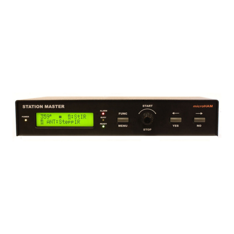
microHAM STATION MASTER DeLuxe User manual

microHAM © 2016 All rights reserved
TABLE OF CONTENTS
CHAPTER PAGE
1. FEATURES AND FUNCTIONS ................................................................................................... 4
2. IMPORTANT WARNINGS .......................................................................................................... 5
3. HARDWARE DESCRIPTION ...................................................................................................... 6
Front Panel .......................................................................................................................... 6
Rear Panel ...........................................................................................................................8
uLINK odules .................................................................................................................... 9
uLINK Bus ..........................................................................................................................11
4. BLOCK DIAGRAM .................................................................................................................... 12
5. INSTALLATION ...................................................................................................................... 12
Configuration anagement/Terms..................................................................................... 13
Preparing Station aster Deluxe for Use........................................................................... 16
Installing microHA USB Device Router ............................................................................18
Configuring microHA USB Device Router ...................................................................... 19
Station aster Deluxe Status ............................................................................................ 19
Creating and Using Virtual Serial Ports ............................................................................. 20
6. micr HAM DEVICE ROUTER .................................................................................................. 21
enu: Router .................................................................................................................... 21
enu: Preset ..................................................................................................................... 22
enu: Device .................................................................................................................... 23
enu: Virtual Port ............................................................................................................. 24
enu: Help .........................................................................................................................25
Device Configuration Tabs ................................................................................................ 26
Ports Tab .................................................................................................................... 26
Ports: CAT & 2nd CAT .......................................................................................... 27
Ports: Rotator & 2nd Rotator ................................................................................. 29
Ports: Auxiliary .................................................................................................... 29
Ports: Control ..................................................................................................... 30
Ports: iLINK ........................................................................................................ 30
Keyboard Tab ..............................................................................................................31
Display Tab ..................................................................................................................32
System Settings Tab ...................................................................................................33
Configuration anagement Tab .................................................................................34
Control Boxes ..................................................................................................... 35
Rotators .............................................................................................................. 40
RF Boxes ............................................................................................................ 45
RF Boxes - Radio ........................................................................................ 45
RF Boxes - Twp-port Device ........................................................................ 47
RF Boxes - Antenna ..................................................................................... 54
RF Boxes - Switch........................................................................................ 59
RF Boxes - Special Devices ........................................................................ 65
Global Attributes ................................................................................................. 68
Virtual Rotators ................................................................................................... 73
Antenna Groups ................................................................................................. 74
Bands ................................................................................................................. 75
Security ............................................................................................................... 77
2

microHAM © 2016 All rights reserved
7. OPERATING STATION MASTER DELUXE ............................................................................. 76
8. CONNECTING SMD HARDWARE ........................................................................................... 87
Output Ports .................................................................................................................... 87
Rotator Port ...................................................................................................................... 88
Power Amplifier Port ........................................................................................................ 91
Serial Port …...................................................................................................................... 91
Important Considerations ................................................................................................. 93
9.CONNECTING uLINK HARDWARE ............................................................................................. 94
uLINK HUB, connection and troubleshooting …................................................................ 94
uLINK RELAY 6/10 ........................................................................................................... 99
uLINK ROTATOR ............................................................................................................101
uLINK DATA ....................................................................................................................104
10. CONFIGURATION EXAMPLES .............................................................................................. 106
Single Radio, Dual Receive Example ...............................................................................106
Basic Dual Radio (SO2R) Example ..................................................................................124
Advanced Dual Radio (SO2R) Example ......................................................................... 125
ultiple Radio Configuration ........................................................................................... 126
11. SYSTEM CONSIDERATIONS ................................................................................................ 128
12. HARDWARE SPECIFICATIONS ........................................................................................... 129
S D: Hardware Specifications & Connectors ..................................................................129
uLINK HUB: Hardware Specifications & Connectors ........................................................134
uLINK RELAY 10: Hardware Specifications & Connectors ............................................. 135
uLINK RELAY 6: Hardware Specifications & Connectors .............................................. 136
uLINK ROTATOR: Hardware Specifications & Connectors...............................................137
uLINK DATA: Hardware Specifications & Connectors ......................................................138
13. PACKAGE CONTENTS .......................................................................................................... 139
14. WARRANTY ............................................................................................................................139
DECLARATION OF CONFORMITY ...................................................................................... 140
APPENDIX A – Tracking ....................................................................................................... 141
APPENDIX B – Cables and Bridges ..................................................................................... 142
3

microHAM © 2016 All rights reserved
1 – FEATURES AND FUNCTIONS
General:
•Programmable Antenna, BPF, Rotator and PA controller
•Twenty (20) programmable relay outputs for local use
•Integrated level converter for transceiver CAT control port
•Decodes all frequencies of connected transceiver, including 75m, 6m, VHF and UHF
•Unlimited number of custom defined frequency segments “bands”
•Single USB connection to computer
•Stand alone operation
•Internal Rotator control
•Virtual Rotators function
•Separate RX/RX2/TX antenna support
•Automatic Antenna Scan function
•Unlimited number of custom defined sequencer outputs
•Automatic power amplifier support
•Fully compatible and simple integration with microHA “keyers” (microKEYER, DigiKeyer, CW Keyer,
microKEYER II, and K2R). Advanced integration with microKEYER II and K2R(+).
•Proprietary SteppIR and UltraBeam support for selective automatic tuning and protection
•Hot Switch protection with user defined timing
•TX Inhibit support for Yaesu, Ten-Tec and Elecraft K3 transceivers
•Receive only antenna support
•Optical isolation from computer
•PS/2 keyboard or keypad with dual control of Station aster Deluxe and microHA “keyer”
•Integrated chokes and filters for maximum RFI resistance
•etal/Aluminum case, powder coated and silk screened
•Free, no time limit firmware/software upgrades via Internet
Radio control:
•Integrated level converter for CI-V, FIF-232, IF-232, or RS-232
•Up to 57600 Baud with fake handshake support
•Supports most Elecraft, Icom, Kenwood, Ten-Tec, Yaesu and other radios
•iLINK connectivity to microKEYER II and K2R(+)
Antenna Control (Port A):
•Ten (10) programmable relay outputs
•Configurable common
•ground
•13.8V positive
•external power, max. + 24V
•Programmable break-before-make delay
•Compatible with all remote antenna switches using common ground or positive control
Additional Antennas or BPF Control (Port B):
•Six (6) programmable relay outputs
•Configurable common
•ground
•13.8V positive
•external power max. + 24V
•Compatible with all automatic BPF on the market
•Four (4) programmable relay outputs
•Both poles of relay contact available
4

microHAM © 2016 All rights reserved
Internal Rotator Control:
•Three (3) programmable relay outputs
•Both poles of relay contact available
•Configurable support for BRAKE or SPEED control
•Support for multi-turn rotators
•Support for rotators with analog (pot) or discrete (pulse) azimuth read back
•Programmable software limit switches
•Dead zone definition
•Target finding strategy selection for optimal handling
•Support for “slipping” rotators
•Four memories for most wanted azimuths
•Automatic azimuth control from logger
Virtual Rotator Control:
•Unlimited number of antennas can be joined to Virtual Rotator
•Programmable azimuth ranges for each Virtual Rotator antenna
•Automatic azimuth control from logger
•Unlimited number of Virtual Rotators per Band
Power Amplifier Control:
•Automatic tuning for CI-V controlled automatic amplifiers (Icom PW1, Expert SPE, O -Power)
•Automatic band switching for BCD controlled amplifiers (Yaesu VL-1000, FL-7000)
•Support for QSK Power Amplifiers
•Support for “shared” Power Amplifiers
uLINK Features
•Allows control of all station devices (antennas, rotators, amplifiers) by multiple operating positions
•Virtually unlimited number of configurable relay outputs
•Virtually unlimited number of rotators
•Virtually unlimited number of serial port control devices
•Support for stacked antennas including complex topologies (e.g., stacked stacks)
•Intelligent rotator control including linked/slave rotators like rotator on rotary tower
•Configurable interlocks to prevent damage and support various operation styles or contest rules in any
kind of multi-transmitter stations
•Special handling of "shared" devices – e.g., muti-band antennas, shared amplifiers, SteppIR and
UltraBeam antennas
2 - IMPORTANT WARNINGS
ALWAYS check the p larity f the 13.8 V p wer supply.
If y ur radi includes upgradeable firmware
DO NOT perf rm any upgrade thr ugh Stati n Master Deluxe.
5

microHAM © 2016 All rights reserved
3 - HARDWARE DESCRIPTION
Fr nt Panel
1. STATUS LEDs
POWER
LED lights when +13.8V is applied (power switch on).
ALARM
LED lights when “ALAR ” condition happens, transmission may be inhibited.
BUSY
LED lights when “BUSY” condition happens, transmission is inhibited.
LED flashes when “BUSY” condition happens, transmission is allowed.
READY
LED lights when transmission is allowed.
LED flashes when transmit condition has been changed and will be applied on next transmission
cycle.
uLINK
LED lights when uLINK interface is powered from uLINK HUB.
2. FUNC/MENU
Short press and release opens “Function” list.
Press and hold for more than one second opens “ enu” list.
3. Antenna selecti n nr. 1
4. Antenna selecti n nr. 2
5. Antenna selecti n nr. 3
6. Antenna selecti n nr. 4
7. Antenna selecti n nr. 5
8. Antenna selecti n nr. 6
9. Antenna selecti n nr. 7/NEXT
Antenna selection nr. 7. If there are more than 7 selections this button moves to next page of
antenna selections
6

microHAM © 2016 All rights reserved
10. RX1-RX2-TX/RX SPLIT
A short press moves between antenna selections for the RX1, RX2 and TX paths
Press and hold for more than one second toggles RX1/RX2 receive antennas split “RX SPLIT”
RX SPLIT is indicated by small 1 or 2 number on left side of focus mark
11. [1] Antenna sub-selection nr. 1
12. [2] Antenna sub-selection nr. 2
13. [3] Antenna sub-selection nr. 3
14. [4] Antenna sub-selection nr. 4
15. MB1, MB2, MB3
Short press and release recalls memory bank 1, 2, or 3 settings.
Press and hold for more than one second stores current settings to memory bank 1, 2 or 3.
Each memory bank is band-dependent.
16. ENCODER
Rotary encoder with push button. Functions vary based on configuration and antenna selection.
17. <-/YES
Button for browsing backward among available antennas and menu navigation.
18. ->/NO
Button for browsing forward among available antennas and menu navigation.
19. PATH/TX SPLIT
Short press invokes selected PATH properties menu if exist.
Press and hold for more than one second toggles RX/TX antennas split, “TX SPLIT”.
TX SPLIT enabled is indicated by yellow led above button.
7

microHAM © 2016 All rights reserved
Rear Panel
1. DC 13.8V
Power Supply - 2.1 x 5.5 mm coaxial jack, center is positive (+).
IMPORTANT: Be sure t bserve the pr per p larity!
2. iLINK
iniDIN-6 for connection with microHA KII, K2R or function expansion module.
3. USB
USB B connector for computer connection.
Standard USB A-B cable.
4. SERIAL
RS232 level serial port.
DB9 female jack.
See “Connecting Hardware” chapters for details.
5. PA
DB15 female jack for connection with Power Amplifier.
Compatible with microHA “PA” cables.
See “Connecting Hardware” chapters for details.
6. PORT A
DB25 female jack for antenna switch connection.
See “Connecting Hardware” chapters for details.
7. PS/2
iniDIN6 for PS/2 keyboard or PS/2 keypad.
8. INHIBIT
Power inhibit output for transceiver.
RCA jack TIP - Signal SHELL – GND.
9. CAT
4 pole 3.5mm phone jack for transceiver control. Compatible with microHA “CAT” cables.
10. GND
Terminal for connection to station ground.
11. iLINK
iniDIN-6 for connection with microHA microKEYER II, K2R, or function expansion module.
8

microHAM © 2016 All rights reserved
12. POWER
Power Switch.
13. ROTOR
DB15 female for connection with Antenna Rotator.
See “Connecting Hardware” chapters for details.
14. PORT B
DB25 female for antenna switch, BPF and/or sequencer connection.
See “Connecting Hardware” chapters for details.
15. PTTIN
input for PTT output from transceiver or PAPTT from microHA “keyer”.
Active when grounded.
RCA jack: Tip – signal, Shell – ground.
16. uLINK
uLINK network connection.
DB9 female jack.
See “Connecting Hardware” chapters for details.
uLINK MODULES
uLINK odules are micro-controller based remote boxes used for control and interface of “shared” devices.
“Shared” devices are all devices included in the station setup which have to be available to and controlled by
more than one station (S D). Such shared devices are antenna switches, stack switches, four square
controllers, rotator controllers, tuners, serial port wattmeters, matching networks, power amplifiers etc …
microHA provides several modules with different control interfaces and functions to control a variety of shared
devices.
uLINK HUB
The uLINK HUB serves as a concentrator and isolated power source of S D
controllers connected to the uLINK bus. Up to four S Ds can be connected to
one uLINK HUB. uLINK HUB is a basic element of the uLINK network, every
setup must contain at least one.
Each S D is connected to the uLINK HUB by single CAT5/6 cable but the
connection uses two wire pairs - one incoming, one outgoing - to maintain the
daisy-chain topology. The third and fourth pairs are used for feeding isolated
power from uLINK HUB to uLINK circuits in the S D to keep uLINK bus isolated
from all other circuits, minimize interference, maximize immunity and keep bus
functionality even when some stations are turned off. The power pairs are connected in parallel to decrease
resistance. There is a dedicated LED on the front panel of S D, indicating that the uLINK bus is powered.
uLINK RELAY6
uLINK RELAY 6 and uLINK RELAY 10 are the most used uLINK network module – they
provide relay contact outputs for device control. The relay modules are used for any
device requiring simple control – switch input to ground, connect to power or connect two
input ports together. uLINK RELAY6 has six (6) isolated SPST contacts located at top
terminal. Each contact is rated 3A @ 125VAC or 30VDC.
This module could be used for interfacing devices with few control lines; AC/DC
controlled devices (like a K9AY controller or Ameritron RCS-4), making AND or OR logic
condition; whenever access to both terminals of the contact are necessary; and when
connection to a common positive or common ground is not an option.
9

microHAM © 2016 All rights reserved
uLINK RELAY10
uLINK RELAY10 has ten (10) separate relay contacts and one common pole located at
top terminal. Each contact is rated 3A/125VAC/30VDC. Common pole can be connected
by external wire jumper to GND terminal pin for sinking outputs (connected to ground) or
to +12 OUT terminal pin for 12V sourcing output. If controlled device requires different
control power it can be applied to the C and GND terminal.
This module can be used with almost all antenna switches on the market including
microHA switches as well as DX Engineering or Array Solutions boxes.
uLINK ROTATOR
uLINK ROTATOR is an uLINK module which can control commercial or home made
rotator with discrete control of AC or DC (non PW ) motors.
uLINK Rotator supports either analog sensor (pot) or pulse counting sensor (reed contact)
direction indicators. There are three relay contact outputs (CW, CCW and AUX). AUX
may be configured as either SPEED (Yaesu style) or BRAKE (Hy-Gain style). LEDs
CCW, AUX and CW on the bottom row indicate currently actuated relays. Contact current
rating is 16A/250VAC/30VDC.
uLINK DATA
uLINK DATA is designed to control data devices and supports: one RS232 serial port with
RTS/CTS, a CI-V port (translates frequency of the transceiver coupled to S D into the
Icom protocol, two configurable inputs, two configurable open collector outputs and one
optically isolated output.
These capabilities allow uLINK DATA to control most automatic power amplifiers, serial
antenna tuners, rotators with RS232 ports, SteppIR/UltraBeam controllers, and other
RS232 devices. The list of supported devices will be extended based on users request.
Alternatively, the serial port outputs can be switched to BCD TTL BAND DATA outputs
by moving four (4) jumpers to BAND DATA position. By default, uLINK DATA jumpers are
set to RS232 serial port.
10

microHAM © 2016 All rights reserved
uLINK BUS
uLINK is a name for microHA station network. It is an isolated, industrial standard RS-485 multi-master bus
which provides device control networking for the S D system. All S Ds are connected to the uLINK bus
through uLINK HUB boxes and share control of multiple uLINK modules. These modules serve as network
interface devices to control antenna switches, stack switches, four square switches, rotator controllers, tuners,
power amplifiers, etc …
NOTE: uLINK bus is completely different from, and independent of, a computer LAN network, never connect
them together.
Every uLINK device on the network is identified by its unique network address. uLINK supports up to 31 S D
controllers (31 radio operating positions in any combination from 31 individual operating positions to 15 SO2R
operating positions). Each S D can access up to 128 uLINK interface modules.
Hardware bservati ns:
uLINK bus is strictly a linear bus; the physical connection must be a daisy chain, going from one device
(module) to another. Total length of the uLINK bus must n t exceed 1.2km (4000 ft). Star topology is not
allowed.
uLINK, is a transmission line having specific impedance and must be properly terminated at both ends. uLINK is
designed to match the impedance of easy to obtain CAT5/6 cables which should be used as the network media.
The bus uses one pair of shielded cable for data, one, parallel connected, pair as a common relative reference
point and two pairs for power distribution. Details are described in the Connecting Hardware chapter.
IMPORTANT: If possible, put the control cable under ground if the control cable runs outside the shack into the
antenna field. The control cable can lay on the ground but avoid placing it near the end of radials, close
to transmitting elements or antenna feed points. Never allow the control cable to hang in open air where it
can pick up RF!
11

microHAM © 2016 All rights reserved
4 – Bl ck Diagram
Station aster Deluxe block diagram
5 - INSTALLATION
Installing Station aster Deluxe (S D) consists of several steps:
1) Read this manual c mpletely - there is n quick setup!
2) D n t c nnect p wer t Stati n Master Deluxe until instructed t d s !
3) D cument y ur stati n. Prepare a diagram showing the entire system with all switches, antennas,
rotator controllers, filters, power amplifiers, etc.
4) Layout and install the uLINK network.
5) Prepare Station aster Deluxe for your station – set the jumpers, make the necessary connections to
antenna switches, power amplifiers, rotators, the uLINK bus, transceiver and microHA Keyer (if
present)
6) Install microHA USB Device Router (the control and interface software).
7) Configure Router and Station aster Deluxe for the hardware in your station (see the “Connecting
Hardware” chapters of this manual for details).
8) Load the configuration and verify that the setup perates as intended!
9) Enj y!
12

microHAM © 2016 All rights reserved
CONFIGURATION MANAGEMENT TERMS
In order to make a valid configuration there are several precautions which have to be observed.
•Layout and document your RF installation. It is vital to start with a diagram showing the entire system,
including every component - transceivers, antennas, switches, amplifiers, filters, rotators etc. Station
aster Deluxe must know every device in the system in order to control everything correctly and safely.
In this manual, components of the RF setup are called “RF B xes.”
•Give every RF BOX a short but easily understood name. This name will be included in many of S D
reports.
•Add the controls for every RF BOX. Document the number and function of the control wires, the type of
any RELAY control unit - ANTenna switching, FReQuency based switching, SEQuenced switching,
ANual, - the type of ROTATOR modules, and DATA modules.
•Define addresses and units for the uLINK modules and verify the design.
13

microHAM © 2016 All rights reserved
TERM RF BOX
RF box is any device in the RF system controlled by S D or uLINK module. RF boxes have “A” and
“R” ports. Termination points - transceivers and antennas - are special RF boxes which have only A
ports (transceivers - a simple transceiver has one A port, a dual RX transceiver with separate 2nd RX
antenna port has two A ports) or only R ports (antennas). Other RF boxes can have more than one R or
A port; for example, a 6 way antenna switch has one R port and six A ports. A Band Pass Filter or Power
Amplifier has one R and one A port. Our Double Ten Switch has two R ports and ten A ports.
IMPORTANT: The only valid connection is from one A port to one R port. Connecting ports in parallel,
connecting an A port to another A port or an R port to another R port is not allowed.
TERM CONTROL BOX
Generally stands for uLINK module or Relay Unit.
TERM A PORT
Is a port of the RF box which connects to another RF box going toward the antenna.
TERM R PORT
Is a port of RF box which connects to another RF box going toward the transceiver (radio).
TERM ADDRESS
Every device (S D and uLINK module) on the uLINK Bus is identified by its unique address. The
address range from 1 t 31 is reserved for S Ds and addresses from 32 t 254 are designated for
uLINK modules. Address 0 and 255 are reserved. The address for S D is set in Router. Addresses of
the uLINK modules are set on the module.
TERM UNIT
Unit is a group of outputs on a uLINK RELAY module used to control a specific RF Box. Outputs are
grouped into units. One uLINK Relay odule may be used to control multiple RF Devices and two uLINK
Relay modules may be paired to control an RF device requiring more than 10 control lines.
For example: we might to control two RF devices - a 6 way switch and a 4SQ box - using one uLINK
Relay10 module. Since the Six way switch needs 6 control wires and the 4SQ box needs 2 control wires,
we would define two (2) units for this module. The first unit would have six outputs for the Six Switch, the
second unit would have two or three outputs for the 4SQ. Any remaining outputs could be assigned to a
third and/or fourth unit for use with another device.
IMPORTANT: One unit always consists of a continuous sequence of outputs. Relay outputs may be skipped
only between units. Pin numbering always begins at the lowest output on the first unit and continues
upward.
NOTE: One uLINK relay module can be divided into a maximum of four (4) units.
NOTE: The local ports of S D (PORT A and PORT B) are treated as 20 outputs in at most 10 units.
TERM SLAVE MODE
Slave mode is a special behavior of a uLINK RELAY module used only when an RF switch requires more
than 10 control lines. Typical examples are the Double Six Switch (12 lines) or Double Ten Switch (20
lines). If module is set as slave, all of its outputs - six (6) for uLINK RELAY6 or ten (10) for uLINK
RELAY10 - are treated as a single SLAVE unit. The first unit of any other uLINK Relay module can be
used as the aster (enable) for this unit.
14

microHAM © 2016 All rights reserved
IMPORTANT: All outputs on the slave module must be used. aster for a slave module must be the first unit
(Unit 1) of a different module. Pin numbering always begins with the first (lowest) output of the slave unit
and continues upward with the lowest output on the first unit of the aster module.
NOTE: RF boxes (switches) and associated items (rotator, serially-controlled devices, etc.) connected to the
local ports of S D can be controlled only from that S D. Any resource that is to be shared among
multiple positions (transceivers) - for example, shared antennas or shared amplifiers, must be connected
to uLINK modules.
TERM START POINT
START point is always a single A port of the transceiver, RX/TX or RX2 port.
TERM END POINT
End points are generally antennas (complete END point). However, in specific situations END POINT
can be any R port (an incomplete or “dead” END).
NOTE: When an incomplete end point is used in an antenna selection, S D “fills out” the connections from that
point with the last used control values from its memory. These values use the appropriate values for TX,
RX or RX2 but d n t consider frequency dependencies. S D considers frequency nly when using
complete endpoints (explicit paths). As an example, a radio's start point is connected to the antenna
switch with two antennas - one antenna for 160m and second antenna for 80m. Both bands have to
antennas defined - one using complete end point (the specific antenna) and a second (incomplete)
endpoint defining only the antenna switch. If the last used antenna selection for 80m was the incomplete
path ending at the switch and the last used 160m antenna was the specific 160m antenna, on switching
from 160 to 80m S D will select “last used” antenna for 80m (the path ending at the switch) and the last
used state of the switch (the 160m antenna) thus selecting the wrong antenna.
S D uses additional, real time error checking for protection, so transmission will be not allowed. Once
the complete endpoint (80m antenna) is selected, S D will remember that selection and the proper path
will be used (even if an incomplete path is selected) until the next band change. Avoid using incomplete
paths whenever possible.
TERM ANTENNA SELECTION
Is a term for user choice of which Antenna Path will be built when pressing one of the seven main
Antenna Selection buttons. Virtual Rotators and Antenna Groups are special types of Antenna Selections
- both will be explained separately.
TERM ANTENNA PATH
The complete connection from the START point to one or more END points including all attributes
involved in the signal path.
NOTE: Antenna Path may not be just a simple connection from START to END point, it may have several
“branches”, each having its END point definition.
These terms are defined here because they will be used through this manual and we will not explain them
again. When a new term is introduced, it will be marked with a TERM icon.
15

microHAM © 2016 All rights reserved
Preparing Stati n Master Deluxe f r Use
D N t turn the Stati n Master Deluxe On until instructed t d s !
C nnecting Stati n Master Deluxe with micro KEYER, DigiKEYER, DigiKeyer II r CW KEYER:
1. If your station includes a microHA microKEYER, DigiKeyer, DigiKeyer II, or CW KEYER disconnect the
computer control lead (CAT) from the radio. Connect the appropriate CAT cable (optional accessory) for
your radio to the CAT jack of S D and the computer control port of your radio.
2. Connect a RCA cable (supplied) from the PTTIN jack on Station aster Deluxe to the PTT output
(amplifier PTT) of your transceiver. Refer to the Operator's anual for your transceiver for the proper
signal connection. PTT output is on the RE OTE DIN for Kenwood, the Band Data jack for Yaesu, and
ACC2 (DIN 7) for Icom.
If your transceiver does not have an RCA connector for PTT Output, it will be necessary to make the
proper adapter.
IMPORTANT: This connection is required for proper operation of Station aster Deluxe with VOX.
3. Using an RCA “Y” cable (Radio Shack 274-881 or equivalent, not supplied), connect the PAPTT output of
microKEYER or DigiKEYER or the PTT output of CW Keyer to the PTT IN jack of Station aster Deluxe.
4. If your transceiver has an INHIBIT input (Yaesu often labels INHIBIT “LINEAR” on the BAND DATA jack),
connect the inhibit input of your transceiver to the INHIBIT output jack of S D.
IMPORTANT: Connecting INHIBIT is best way to prevent hot switching.
5. Remove the top cover from Station aster Deluxe and set the CAT jumpers as shown in the following
chart. The CAT interface jumpers must be configured to select the proper signal level for your
transceiver.
RS-232 levels:
All transceivers with RS-232 CAT inputs
IF-232 levels:
Kenw d: TS-140, 440, 450, 680, 690, 711,
790, 811, 850, 940, 950
FIF-232 levels:
Yaesu: FT-100, 736, 747, 757GXII, 767, 817,
840, 857, 890, 897, 900, 980, 990, 1000, 1000D
CI-V levels:
Ic m: all radios (except 7700/78xx when
using the DB9/RS-232 jack)
TenTec: all radios with 3.5 mm jack
NOTE: the CAT interface is not configured at the factory.
16
RS232
FIF232
CI-V
IF232

microHAM © 2016 All rights reserved
C nnecting Stati n Master Deluxe with micro HAM micro KEYER II, MK2R r MK2R+
1. If your station includes a microHA microKEYER II or K2R or K2R+, keep the computer control
(CAT) connection from the microHA keyer connected to the radio. The Station aster Deluxe CAT jack
will not be used for radio control.
2. Connect the supplied 6 pin mini-DIN cable from one of the iLINK jacks (the jacks are identical) on Station
aster Deluxe to the RE OTE jack of the keyer. If you are connecting two Station asters Deluxe units
to a K2R or K2R+, connect an iLINK cable to each S D.
3. If your transceiver has an INHIBIT input (Yaesu often labels INHIBIT “LINEAR” on the BAND DATA jack),
connect the inhibit input of your transceiver to the INHIBIT output jack of S .
If you are connecting two S D units to the K2R or K2R+, be careful to connect the INHIBIT line from
from Radio1 to the S D associated with with Radio 1 and INHIBIT signal from of the Radio 2 to the S D
associated with Radio 2.
IMPORTANT: Connecting INHIBIT is best way to prevent hot switching.
C nnecting Stati n Master Deluxe with ut a micro HAM “keyer”
1. If you don't have a microHA “keyer,” connect the appropriate CAT cable (optional accessory) for your
transceiver from the CAT jack of Station aster Deluxe to the computer control port of your radio.
2. Connect an RCA cable (supplied) between the PTTIN jack on Station aster Deluxe and the PTT output
of your transceiver. Refer to the Operator's anual for your transceiver for the proper connection.
3. If your transceiver does not have an RCA connector for PTT output, it will be necessary to build the
proper adapter. PTT output is on the RE OTE DIN for Kenwood, the Band Data jack for Yaesu, and
ACC2 (DIN 7) for Icom.
IMPORTANT: This connection is required for proper operation of Station aster Deluxe with VOX.
4. If your transceiver has an INHIBIT input (Yaesu often labels INHIBIT “LINEAR” on the BAND DATA jack),
connect inhibit input of your transceiver to the INHIBIT output jack of S D.
IMPORTANT: Connecting INHIBIT is best way to prevent hot switching.
5. Remove the top cover from Station aster Deluxe and set the CAT jumpers as shown in the following
chart. The CAT interface jumpers must be configured to select the proper signal level for your
transceiver.
RS-232 levels:
All transceivers with RS-232 CAT inputs
IF-232 levels:
Kenw d: TS-140, 440, 450, 680, 690, 711, 790,
811, 850, 940, 950
FIF-232 levels:
Yaesu: FT-100, 736, 747, 757GXII, 767, 817, 840,
857, 890, 897, 900, 980, 990, 1000, 1000D
CI-V levels:
Ic m: all radios (except 7700/78xx when
using the DB9/RS-232 jack)
TenTec: all radios with 3.5 mm jack
NOTE: the CAT interface is not configured at the factory.
17
RS232
FIF232
CI-V
IF232

microHAM © 2016 All rights reserved
Installing microHAM USB Device R uter
IMPORTANT: Locate the USB cable but DO NOT
connect it to the USB jack of Station aster Deluxe at
this time.
To install Router click on the Install USB evice
Router link on the installation CD or download the most
recent installation package from the web site:
www.microham.com/contents/en-us/d29.html
If you download an updated package, right click on
"urouter_release_xx_xx.exe" (xx_xx is version) and
choose “Run as administrator” to start installation.
The Windows setup utility will start and ask into which
folder Router and its supporting files should be
installed. Note: unless you have a very strong reason
to install Router elsewhere, please accept the default
location.
When the Router installation is completed, click
"Finish" to launch Router for the first time.
•Connect a 13,8 to 16V DC supply to the DC 13.8V jack of S D.
Be sure t bserve the pr per p larity.
•Plug in the USB cable.
•Turn on the Station aster Deluxe and proceed to Configuration anagement tab of Station aster
Deluxe device to enter your station configuration.
18

microHAM © 2016 All rights reserved
C nfiguring microHAM USB Device R uter
The microHA USB Device Router (Router) program provides a Windows compatible configuration tool for
microHA USB Devices (Station aster Deluxe as well as microKEYER II, DIGI KEYER, microKEYER, CW
Keyer and USB Interfaces) and software interface to other Windows applications (logging software, digital mode
software, etc.). The software interface is provided as Virtual Serial Ports.
In order to configure and use Station aster Deluxe with Windows compatible application programs, you must
be running Router and have turned on Station aster Deluxe Router is then configured as required by the
application (logging, control or digital mode) software.
Stati n Master Deluxe Status
When the USB driver is installed correctly and Station aster Deluxe
is turned on Router will show a device tab with a GREEN beside
the device name.
When Router shows a YELLOW “X” instead of a green , it means
the USB driver is correctly installed but Router can not communicate
with the controller in Station aster Deluxe. This is usually because
S D is not turned on.
When Router shows a RED “X” instead of a green , it means the
device is disconnected and Router does not see the USB part of
Station aster Deluxe. This happens when the USB cable is
unplugged or the USB driver is not correctly installed.
19

microHAM © 2016 All rights reserved
Creating and Using Virtual Serial P rts
microHA Router provides a set of virtual serial ports which allow Windows applications (logging or control
software) to work with Station aster just as they would work with "real" (hardware) serial ports.
In order to use these virtual Ports, you must first create the ports and then assign a port to each function you
wish to use (CAT radio control, Rotator, etc.).
DO NOT define a port that is already in use (for example, CO 1 or CO 2 which are hardware ports on many
motherboards) or a virtual port that is used by another USB device. Even though Router will not allow creating a
virtual port on a CO port number which is already present in the system (like hardware CO ports or internal
modems), sometimes these ports are hidden. If another device that also uses virtual ports (external USB
devices, bluetooth devices, mobile phones, PDAs etc.) is not connected when creating virtual ports in Router, the
ports can overlap and will not work properly when you connect such device.
WARNING: Before you begin to create virtual ports, attach all external devices you are using with computer and
allow them to connected to the system. Restart Router and then create virtual ports.
Virtual ports are created and deleted from the Virtual Port menu.
Create - Creates virtual CO ports. It is possible to
select more than one port at a time by holding the Ctrl
key on keyboard and clicking on CO port numbers.
Creating virtual ports may take a long time (several
tens of seconds), be patient.
Delete - Deletes any single virtual port.
Delete All - Deletes all previously created virtual ports.
Do not delete a virtual port until all applications using
that port have been closed.
TIP: If you have removed another device which used virtual ports and Router does not offer the released
port number, you will need to reset the virtual port bus. You can do this by deleting all virtual ports in
Router at once. Select "Virtual Port | Delete All" then create the ports again. Any missing CO port
numbers should appear.
20
Other microHAM Controllers manuals
Popular Controllers manuals by other brands

Toshiba
Toshiba BMS-CT1280E owner's manual

Regin
Regin RVAPC-24A instruction manual

Unitronics
Unitronics UniStream USC-B5-R38 installation guide

B&K
B&K Reference 20 Plus A/V System Controller owner's manual

Viessmann
Viessmann VITOTRONIC 300 Installation and service instructions

EPC
EPC EP-2000 Technical reference manual