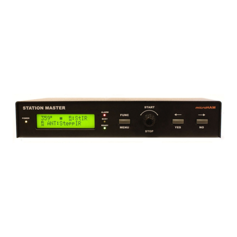
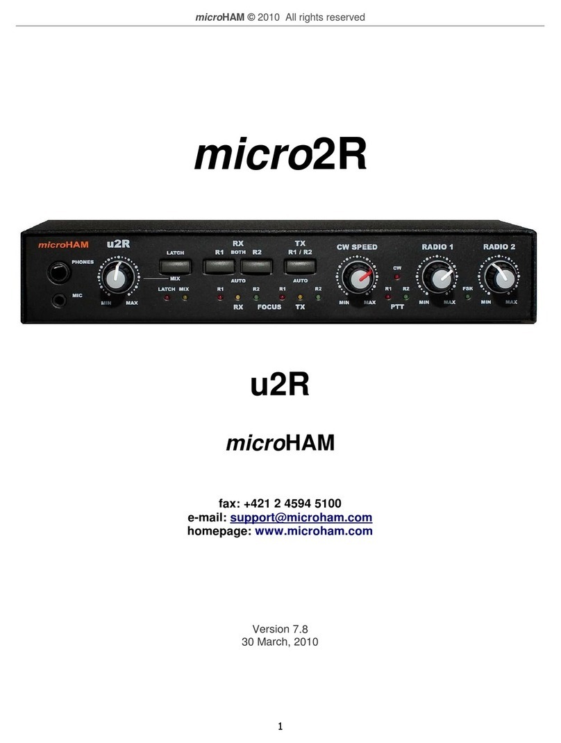
microHAM ARCO User manual

microHAM © 2021 All rights reserved
TABLE OF CONTENT
1 - DEVICE DESCRIPTION ................................................................................................................4
- PANEL DESCRIPTION ................................................................................................................. 5
Front anel .................................................................................................................................................. 5
Rear anel .................................................................................................................................................... 6
3 - SETUP ........................................................................................................................................... 7
Rotator reset ............................................................................................................................................... 8
Rotator Center .............................................................................................................................................. 9
Calibration ................................................................................................................................................... 10
4 - USER INTERFACE ..................................................................................................................... 1
5 - SETTINGS MENU .......................................................................................................................14
General ....................................................................................................................................................... 14
Appearance ................................................................................................................................................ 15
Appearance - Global ................................................................................................................................... 15
Appearance - Zoom 1..4 ............................................................................................................................. 15
Rotator - Settings ........................................................................................................................................ 16
Rotator - Link .............................................................................................................................................. 18
Heading ...................................................................................................................................................... 20
LAN ............................................................................................................................................................. 21
Internet Remote Control .............................................................................................................................. 22
System ........................................................................................................................................................ 23
USB Firmware Update ................................................................................................................................ 24
USB Serial ort ........................................................................................................................................... 25
6 - HARDWARE SPECIFICATIONS ................................................................................................. 6
7 - PACKAGE CONTENTS .............................................................................................................. 7
8 - WARRANTY ................................................................................................................................ 7
DECLARATION OF CONFORMITY ................................................................................................. 8
APPENDIX A – ARCO CONNECTORS ........................................................................................... 9
APPENDIX B – ROTATOR SETTINGS & CONNECTIONS .............................................................30
APPENDIX C – CUSTOM ROTATOR SETTINGS & CONNECTIONS .............................................39
APPENDIX D – LINE INPUT 115/ 30 VAC SWITCHING .................................................................43
TRADEMARKS
Yaesu is a trademark of Yaesu/Vertex Standard USA
Hy-Gain is a trademark of Hy-Gain Corporation
Orion is a trademark of M2 Antenna Systems
TIC RingRotor is a registered trademark of TIC General
All other products, company names, brand names, and trademarks are the property of their
respective owners.
2

microHAM © 2021 All rights reserved
IMPORTANT PRECAUTIONS
Before using the device, check the voltage rating of your local AC mains supply
system and compare to the label located at the rear panel near LINE socket describing
the device LINE input setup.
AVOID opening the device before you have disconnected it from the mains supply.
Any internal settings or repairs have to be done only by an authorized person
according to Appendix D.
DO NOT turn on the device unless it has been properly grounded through the EN
conductor of the LINE mains cord. Do not disconnect this ground under any
circumstances, this may lead to a risk of severe or fatal electric shock.
DO NOT use an extension cord with the AC power cable unless it is correctly rated as
there will be a risk of fire or electric shock.
DO NOT touch the device with damp or wet hands. There will be a danger of electric
shock.
DO NOT allow any objects to enter inside the device.
DO NOT cover the cooling ribs at rear side of the device.
DO NOT expose the device to the high humidity environments.
AVOID permitting children to play with the device.
SET the main switch to the OFF position [O], if you do not use the device for long time.
3

microHAM © 2021 All rights reserved
1 - DEVICE DESCRIPTION
The ARCO is a modern rotator (motor + position sensor) controller designed for reliable
operation with virtually any rotator ever made as well as with the home brew rotators. It is a
completely self-contained stand alone rotator controller not requiring computer or any external
device or power supply for setup and operation, while providing a wide selection of interfaces for
remote control when necessary. It features several ways of controlling azimuth or elevation
heading using uncluttered graphical user interface on the 7” touch screen. Azimuth heading is
displayed on a great circle map, user centered to the rotator installation location, with four
different radius settings, live grey line projection, several coloring options and automatic
day/night color schemes. The controller supports Touch'n Turn feature, fastest possible heading
entry by simple touching desired direction on great circle map. Than classic tactile front panel
CW and CCW buttons, oint and Shot knob and heading entry keypad, either virtual on the
touch screen or hardware, connected to the USB host port on the ARCO.
Along with the manual control, ARCO offers rich connectivity for the computer using standard
RS-232 port, USB serial port not requiring any driver installation on Windows 10, macOS, and
Linux, and Ethernet port to enable control over Internet.
For rotator position feedback, ARCO supports wide range of the absolute and relative sensors
including rheostat, potentiometer, reed contact, Hall sensor, and WM sensor. Additional digital
sensor port provides three differential lines supporting RS-485 communication as well as single
ended push-pull and open collector connection for various quadrature encoders. With high
resolution sensors positioning accuracy is 0.1º.
For the motor control, ARCO uses high current, 4-channel WM driver with overload, short
circuit and overheat protections, combined with automatically operated, current monitoring
internal power supply, preventing driver damage caused by operation failures. This combination
is capable of driving safely any DC motor up to 48V or any AC motor up to 24V, including
innovative brake control reducing solenoid heat. Motor start and stop uses configurable, ultra-
fine gradual speeds ramps, significantly reducing inertial forces stress to the rotator, tower and
antennas, prolonging their lifetime. Gradual speed control uses auto-adapting procedure
considering variable, dynamically changing resistance caused by wind or ice.
ARCO uses built-in linear supply for silent, interference free continuous operation. Separate
built-in power supply for the motor is selectively controlled and entirely turned off when motor
does not turn, to avoid causing any possible interference to the sensitive receivers. For high
voltage or high power motors ARCO provides common control outputs for inverters as well as
industry standard MODBUS RTU control. All rotator settings including compensation for power
loss in the motor cables are menu driven, comfortably without requiring to open cover and
change some internal wiring.
Networking is another strong point of ARCO. ARCO supports not only LAN networking but
allows to build a simple but powerful, isolated two-wire local LINK bus, coupling multiple ARCO
controllers together for automated stacks tracking, multi-directional beaming, and counter
rotation for rotating towers. Unique feature of ARCO is a direct control of rotators connected to
another ARCO controllers, located either on the same LINK bus or anywhere in the world using
Internet connection. All this complex control is greatly simplified by using just two, easy to
handle SYNC and ALIGN buttons, and single ANTENNA button which allows to choose either
one of three antennas installed on the same rotator with different heading offsets, or any other
antenna present on the local LINK network through another ARCO, or on a remote LINK
4

microHAM © 2021 All rights reserved
network through ARCO controller connected over the Internet.
For unattended remote operation over the Internet, ARCO offers autonomous parking function
and physically disconnects all wires coming to the rotator port from the rotator hardware when
connection is over, breaks, or if ARCO goes to the power down mode, in order to minimize
possible damage by high static or nearby lightning during storms.
Firmware provides wide range of additional protections and self explaining error messages for
quick troubleshooting if any failure happens. All of this packed in a full aluminum, compact
enclosure with always free firmware updates.
- PANEL DESCRIPTION
Front Panel
5
1. POWER
Mains power switch
. POWER LED
LED is on when controller is on.
Flashes when controller is in Stand By
mode.
3. FAULT LED
LED indicates operation fault.
4. MOTOR LED
LED is on when power is applied to the
motor.
5. ← CCW BUTTON
Turns motor in counterclockwise
direction.
6. → CW BUTTON
Turns motor in clockwise direction.
7. HEADING KNOB
Sets rotator position. ower is
applied to the motor when knob
stops. Depressing knob will stop
rotator movement.
8. DISPLAY
Touch screen user interface.

microHAM © 2021 All rights reserved
Rear Panel
1. LINE
ower line input. IEC C14 socket.
. FUSE
ower line fuse, 5x20mm T type.
3. LINK
Bus port for linking multiple ARCO controllers together. 3.5mm (1/8”) stereo jack.
4. SERIAL
RS-232 serial port for legacy computer control. DB9 female socket.
5. LAN
Ethernet port, for control over internet. RJ45 socket.
6. USB
USB B port for computer control.
7. FW
USB A port for keypad connection or local firmware update.
8. D-SENSOR
Digital position sensor port, DB15 female socket.
9. ROTATOR
Rotator connection port, 10 position removable terminal, 5.08mm pitch.
10.ROTATOR
Rotator connection port connected in parallel with (9), directly connects YAESU rotators.
11.GND
Rotator cable shield connection, M4 stud. Bonded to chassis.
6

microHAM © 2021 All rights reserved
3 - SETUP
Installation of ARCO consists of hardware and software parts. First, it is necessary to setup the
ARCO software to let controller know what kind of motor and sensor controller has to expect.
For connection to the rotator hardware serve two connectors, removable 10-pins screw terminal
connector (9) and snap-in 6-pins rectangular connector (10), compatible with connectors used
on current YAESU rotators. Corresponding pins on both connectors are internally wired in
parallel.
At first step, DO NOT connect any rotator cables to the ARCO. Make sure the front panel power
switch is off, you should see O sign on its top side. On rear panel verify that the mains voltage
setup label next to the mains FUSE (2) shows the same voltage as is your local mains
distribution.
If it does not match, do not continue and contact your vendor or authorized person to
setup ARCO for your mains distribution rating. Controller has internal 115/230VAC line
voltage selector switch.
Firmly plug your country approved IEC C13 power cord to the LINE socket on the ARCO
controller, than plug other end to the mains socket and turn ARCO on by flipping front panel
power switch.
After a short while you'll see main screen on display. Touch settings icon in the left bottom
corner to enter SETTINGS MENU. On top you'll see several tabs which will be described later,
now touch General tab, touch ROTATOR LOCATION button and enter QRA locator or G S
coordinates of the place where rotator is installed in WGS 84 format. If you don't know, please
find your location on satellite map https://www.gps-coordinates.net/ or check G S coordinates
in your mobile phone. As a result ARCO will show you your QRA locator and vice versa. Than
set current UTC TIME in HH:MM:SS format and current UTC DATE in DD:MM:YYYY format.
Now touch Rotator tab. At Rotator tab select your rotator MODEL from drop down menu. If you
do not see your model listed, select CUSTOM and configure your rotator parameters. lease
refer to SETTINGS MENU | Rotator chapter for parameters description. If you are not sure,
contact us for help.
Settings proper parameters on Rotator tab, namely SENSOR, p/360º (if applicable),
TOTAL ROTATION, BRAKE and LIMIT SWITCHES presence are absolutely
necessary for proper calibration.They are set automatically when you chose particular
rotator model, but if you are going to calibrate custom rotator, make sure all above
mentioned parameters are set correctly.
When you are done touch EXIT tab. ARCO will generate maps centered to rotator location and
register your settings. It takes about 15 seconds per map, please be patient. When job is
finished turn off main power switch and disconnect power cord from the mains socket. If any
error message pop-ups just confirm and ignore it, it is normal as some protections and real time
checks are already running but you do not have a rotator connected yet.
Always turn off main power switch and disconnect power cord when you are
connecting or disconnecting cables to the ARCO controller or replacing controller.
Safety first!
7

microHAM © 2021 All rights reserved
Now you can proceed to the rotator connection. If you are connecting recent Yaesu rotator, you
just need to connect cable end with the 6-pins (2x3) rectangular plug to the rectangular jack (10)
on your ARCO. No other connections are necessary, you can reconnect back power cord, plug
it to the wall socket, turn the controller ON and proceed to the calibration and software setup.
If you are connecting rotator, having different connector cable end, you need to build an adapter
between mating cable jack and 10-pins ROTATOR terminal on ARCO, or cut it and connect
wires to the terminal directly. Terminal is industry standard 5.08mm (0.2”) pitch pluggable screw
terminal block.
We understand, that some users may be hesitant to cut connections to the old controller. As a
solution, use the female version of the screw terminal block. As you cut wires of the cable, one
by one, and connect their rotator end to the male terminal block for ARCO, simply connect the
other end of the cut wire to the respective terminal of the female terminal block. In this way,
whenever desired, the original connection can be simply restored by plugging in the cable into
the stub on the original controller, ending with the newly installed female terminal block.
Take your time, make nice, clean and solid connections. We recommend to use isolated wire
ferrules crimped to the cable wire ends. Wiring diagrams for various rotators included in the
MODEL menu, can be found at the end of this manual, Appendix B. If you are connecting
unlisted or custom rotator, please make connections according to the charts in Appendix C, with
respect to the motor and sensor type.
Once rotator is connected, you can connect back the power cord, plug it to the wall socket, turn
controller ON and proceed to the rotator preset and calibration.
Rotator Preset
In order to know position of your antenna, antenna rotator must be equipped with a position
sensor and controller must be “synchronized” to this sensor. This synchronization process calls
calibration. This requirement applies to any rotator and controller and must be done properly.
Rotator can be equipped with one of two types of the sensors; absolute sensor as
potentiometer, rheostat, WM sensor, absolute encoder, geomagnetic sensor OR relative
sensor like magnetic reed contact, Hall sensor or incremental encoder in any form.
Absolute sensor always provide absolute value of rotator orientation, relative sensor provides
value of the orientation change. ARCO supports both sensor types and internally converts
relative sensor values to an absolute by counting pulses and constant storing last position value
since calibration.
Rotators with relative sensor and without limit switches has free rotation center, but rotators with
an absolute sensor or rotators with hardware limit switches have an exact center and is
desirable to preset rotator to this position to simplify calibration. It is important to realize that
such rotator has its center of orientation fixed, in other words, absolute rotator center is set by
its mounting orientation on rotator's plate. While it is not necessary to mount such rotator in any
specific direction, important is to set rotator to its center and adjust antenna rotation center by
rotating antenna around the mast separately.
Calibration procedure allows to safely find and set such rotator to its center and calibrate
antenna position individually, unrelated to the actual mounting orientation of the rotator.
8

microHAM © 2021 All rights reserved
If you are going to calibrate already installed antenna with proper center alignment, you can skip
next chapter. If you are going to do new rotator installation, perform next instructions.
The most comfortable way to center rotator is to do this prior installation on the tower while is
down, using temporary connection cable. It is also possible to center rotator when is already
installed on the tower together with an antenna, but if it is brand new installation we recommend
to carefully watch the antenna feedline, release it, or entirely disconnect during the process, to
avoid feedline damage.
Rotator Center
INSTRUCTIONS
–Touch the settings icon at the left bottom corner of the main screen to enter menu.
–Touch Heading tab.
–Touch RESET to clear calibration memory.
–Touch AUTO or FIND CENTER button.
AUTO automatically sets rotator to its center, assuming the sensor center is also rotator
rotation center. rocedure takes longer time as automatically finds and register position
of both CW and CCW limits. AUTO function is provided only for rotators with hardware
limit switches.
FIND CENTER automatically sets absolute sensor rotator to its center, assuming the
sensor center is also a rotator rotation center, by shortest possible path without searching
and registering limit positions.
If automatic finding of the rotator center is not appropriate for whatever reason, you can
turn rotator to its center manually using CW and CCW front panel buttons until reading
shows 50%.
Once rotator is centered setup is done, rotator can be installed on the tower. When rotator and
antenna installation is finished, release antenna clamps a bit to be able to rotate it manually
around the mast (mechanically, DO NOT TURN ROTATOR BY THE ARCO) to the North or to
the South or to any other desired antenna rotation center, and firmly tight all clamps. Antenna
positioning does not need to be super accurate as caused error will only influence position of
CW and CCW limits.
From now, antenna can be turned by ARCO controller equally in both CW and CCW directions
by CW and CCW buttons because you've nulled mounting shift and aligned requested antenna
rotation center to the rotator rotation center. You can adjust rotation speed as necessary by
CALIB S EED parameter which sets percentage of nominal power. Turn rotator to both limits
and check for possible feedline problems.
Next step is registering position of hardware limit switches if they exist and accurate calibration
of the antenna position.
9

microHAM © 2021 All rights reserved
Calibration
Before you proceed to antenna position calibration, you need to register or calibrate position of
CW and CCW limits.
LIMITS CALIBRATION INSTRUCTIONS
•If available and rotator can turn within hardware limits touch AUTO button. ARCO will
automatically find position of both CW and CCW limits and set rotator to its center.
•If your rotator has relative position sensor without limit switches, touch SET CENTER
button and enter desired center of antenna rotation, usually 0º for North center or 180º for
South centered rotations, but center can be anywhere from 0º - 359.9º. This azimuth is
used to preset software limit switches according to the TOTAL ROATATION parameter,
symmetrically divided in CW and CCW directions.
•If neither is applicable, calibrate CW and CCW limits manually same way as antenna
heading. Confirm CW or CCW limit on calibration pop-up window.
•Calibrate antenna heading.
ARCO needs at least one calibration point to show antenna heading and it can be entered by
accurate aiming antenna to the known specific direction and than register this direction as a
calibration point by touching appropriate calibration button. ARCO provides several ways of
entering a calibration point. Buttons inside CALIBRATION OINTS area serve to register a
calibration data. All of them have same purpose but provide different choices, choose most
suitable method for you, it doesn't matter which one.
HEADING CALIBRATION INSTRUCTIONS
•Touch the settings icon at the left bottom corner of the main screen to enter SETTINGS
MENU. Now touch Heading tab. Do not touch FIND CENTER, SET CENTER, AUTO or
RESET buttons on the first line unless you want to clear all calibration data and start
calibration from the scratch. If yes, first touch RESET and continue as was described in
previous chapter.
To get antenna to a specific heading use exclusively ← CCW and → CW
buttons on the controller front panel. For setting up accurate position, CW and
CCW buttons do not use ramps (only on this tab) and speed is automatically
limited to CALIB S EED in % of power.
NORTH / SOUTH buttons. If you know accurate North or South position, turn antenna that
direction as accurately as possible and touch appropriate button to register calibration point.
CUSTOM button allows to enter actual antenna heading. If you have rotator with overlapping
segments (TOTAL ROTATION > 360º), make sure the antenna is NOT in any of these
segments. Actual heading can be found by using compass but all compass devices are
influenced by magnetic declination. See more here: https://en.wikipedia.org/wiki/Magnetic_declination
Make sure to check value of the magnetic declination for your QTH:
https://www.magnetic-declination.com/ and add/subtract found value to the compass reading.
Most accurate method of registering calibration point is if you can accurately aim antenna to a
10

microHAM © 2021 All rights reserved
visible distant place which can be found on satellite maps. Find G S coordinates of this distant
point https://www.gps-coordinates.net/, aim antenna to that place and enter coordinates to the
ARCO. Controller consequently compute heading value and register it as an calibration point.
lease note, if you are calibrating antenna heading to G S coordinates, use G S coordinates
for ROTATOR LOCATION first as QRA locator method is too coarse for accurate calibration.
SOLAR AZIMUTH. Since ARCO known your rotator location coordinates, time and date,
controller can compute exact sun position, and knows azimuth of the shadow projected by the
tower on the ground. To use it, you need to turn antenna in direction of the shadow. recisely
align antenna boom shadow in parallel to the mast shadow and touch FORWARD button. Or
turn antenna to opposite direction, align antenna boom shadow in parallel to the mast shadow
and touch REVERSE button.
Once position is calibrated it is confirmed by CALIBRATION STATUS line showing
CALIBRATED message and ANT #1 AZIMUTH will display antenna azimuth.
ARCO allows to set software (SW) rotation limits. By default they are worked out from the
rotation center position and TOTAL ROTATION parameter from the Rotator tab. They can be
narrowed down by touching CW and CCW SW LIMITS buttons.
POST CALIBRATION INSTRUCTIONS
(Rotators with limit switches a d POT a d RHEO se sors)
•If you have rotator with OT or RHEO absolute sensor, for a better accuracy near
rotation ends we highly recommend to calibrate also CW and CCW limits,
even if they are already registered by AUTO button. Reason is that single
turn potentiometric sensors are typically used for its full travel but ends
are usually not linear. In addition, if such rotator has no hardware limits,
travel over these limits will damage sensor, hence is more safe to let ARCO sample
exact position of both limits.
•Turn rotator to desired CW limit position but watch ROTATOR CENTER number to not
exceed 99%. Touch CUSTOM button and enter antenna azimuth. On next window
confirm CW limit position.
•Turn rotator to desired CCW limit position but watch ROTATOR CENTER number to not
run under 1%. Touch CUSTOM button and enter antenna azimuth. On next window
confirm CCW limit position.
•You can increase accuracy and improve heading linearity by adding more calibration
points. ARCO can register up to 72 calibration points if new point is more apart from the
old one than (Total Rotation / 72) degrees, what is 5º for rotators with 360º rotation
range. If new calibration point is within +/- 5º from old, ARCO will delete old, and use new
point instead. osition of calibration points are shown on calibration strip as small yellow
vertical lines.
If you want to reset all calibration data, touch RESET button and restart calibration.
11

microHAM © 2021 All rights reserved
4 - USER INTERFACE
The main display of ARCO provides real time information about antenna heading, antenna
selection, rotator state and six memories for quick antenna heading change.
Heading is provided by orientation needle on great circle and by large heading number which
can be set to show either real time heading or target rotation heading.
Under the heading number is located graphical rotator status displaying actual rotator speed,
turning direction and brake state. Under graphical status is shown self explaining detailed
status of each operation step executed by the rotator controller.
Antenna heading can be set in many ways, by Touch'n Turn - touching great circle map at
desired direction, by Heading Dial Screen - entering specific heading by touching large
heading number area, by memory preset buttons on display, by Point and Shot knob dialing in
required heading, instantly by CCW ← and CW → buttons on front panel, by numeric keypad
attached to the USB A (FW) port on ARCO, and by computer, either thru the RS-232, USB or
Ethernet port.
Touch'n Turn is the fastest heading setting ever bought to the rotator controller. You simply
touch the great circle where you want to turn your antenna and that's all. If you keep finger on
display, by moving it in all directions you can fine tune desired target heading. Rotator will start
movement when you remove finger from the screen.
Heading Dial Screen allows you to enter desired heading not only by large on screen keypad
but it also allows to set heading to QRA locator, specific DXCC country or prefix, or particular
WAZ or ITU zone. Screen shows current and new azimuth, to confirm choice touch the GO
icon. If you want to return back to the main screen without heading change touch RETURN icon.
If you need to stop rotator movement for any reason, press oint and Shot knob or press one of
CW/CCW buttons. If rotator is stopped by the knob, heading can be optionally restored to the
stop position.
ANTENNA button allows to choose one of three antennas if these antennas have different
offset to the main antenna or any available rotator/antenna present on local LINK network or
chosen ARCO controller over Internet.
BACK button serves to return antenna heading to the previous heading. What should be
considered “returnable” heading is defined in the SETTINGS MENU | General.
Next to BACK button is located SYNC switch and ALIGN button. These controls are available
only if SYNC is enabled in the setup Link tab and if you have your controller linked over LINK
bus to the another ARCO controller(s).
SYNC switch enables or disables heading synchronization, basically sends or receive “follow
me” command on the bus on every direction change while keeping heading difference. If is
switched off, rotator works independently, does not send or receive synchronization commands.
ALIGN button sends command to bus for instant alignment of position to match sending
controller's heading. Menu settings specifies which antennas will be aligned.
12

microHAM © 2021 All rights reserved
At the bottom right are located six memory buttons for quick recall or store most used headings.
To recall heading just touch desired button. Touch and hold the button if you want to change
heading or label. Memory buttons supports absolute headings as well as incremental or
decremental heading changes by using +/- sign key. For example for turning antenna to long
path direction by storing and using +180º button.
At the top left corner is shown UTC time of the sunrise or sunset. It is switching automatically,
depends which event is closer. By touching icon it can be switched to the countdown mode
showing how much time remains to the event by using minus sign or expired from the event by
plus sign.
Antenna position at software or hardware limits and overlap, if position exceeds 180º from the
antenna rotation center is indicated by easy to read traffic signs at the middle top of the screen.
Overlap by a roundabout sign, software limit by no left or no right turn sign and hardware limit by
the stop sign. If position of the antenna is in the overlapped section, touching overlap icon will
re-position antenna to the same heading in the non-overlapped section.
At the middle bottom of the screen is an appearance switch, globe with a loupe icon, providing
quick selection for one of four map “zoom” presets for different great circle map radius, colors,
greyline projection etc … Each zoom can be customized in the Appearance menu.
At the bottom left corner is located typical settings button for entering the SETTINGS MENU.
lease note, if you plan to use USB keypad to control directions, be aware that some complex
keypads, especially those embedding other functions such as an embedded display or
touchpad, may in fact be a complex USB device, e.g. embedding an USB HUB, and these may
not work with ARCO. Simple and cheap USB keypads work well.
13
ANTENNA
SELECTION
ANTENNA
DIRECTION
SUNRISE
SUNSET
HEADING
DIAL SCREEN ENTRY
GREAT
CIRCLE MA
MOTOR
SEQUENCE
SETU MA
ZOOM
MEMORY
RESETS
HEADING
RECALL
SYNCHRONIZATION
CONTROL
SUN
OSITION
GREYLINE
STATUS
OVERLA
LIMITS

microHAM © 2021 All rights reserved
5 - SETTINGS MENU
SETTINGS MENU of ARCO controller allows to set individual parameters of complete controller
behavior. There are no internal switches, jumpers or trimmers, all settings can be set here.
General
ROTATOR NAME: Sets rotator name for identification and is also shown on the screensaver.
ROTATOR LOCATION: Sets G S coordinates of rotator installation place in WGS 84 format
(decimal degrees, World Geodetic System 84). Controller shows computed QRA locator.
Settings proper location is important for various calculation, greyline and sun position, and
calibration.
DISTANCE UNITS: Sets ARCO to use kilometers (km) or miles (mil) as a distance units.
TIME: UTC Time in the HH:MM:SS format
DATE: UTC Date in the DD:MM:YYYY format. Accurate time and date is necessary for various
calculations, same as rotator location. Time and date can be automatically synchronized using
NT server, see LAN settings tab.
SCREENSAVER: Specifies time for activating screensaver to avoid display burn out.
Screensaver activates automatically if there is no manipulation with ARCO or no heading
change for a specified time. During screen saving is ARCO fully operational and wake ups
automatically to respond to the computer control as well as to the front panel control.
STAND BY: Specifies time when controller enter Stand by mode. In stand by mode, display,
touch screen and rotator control C U is off. Rotator hardware is physically disconnected from
the controller. Controller can be waken up by pressing hardware buttons, touching knob, by
valid heading command received from RS-232, USB or by valid packet received over LAN.
PARK BEFORE STAND BY: Allows to turn rotator to a specific heading defined in next field
before controller enters Stand By mode.
KNOB STEP: Defines Point and Shot knob steps. It also automatically sets heading number
resolution on the main screen to tenths of degrees (0.1º).
COARSE: Doubles knob sensitivity.
RETURN TO STOP BY KNOB: Enables Point and Shot knob return stop function for restoring
rotator heading to a position at which was stopped.
BACK RETURNS LAST HEADING SET BY: Defines what heading changes are remembered
for returning last heading by BACK button on the main screen.
TOUCH'n TURN: Enables heading settings by touching the great circle map.
14

microHAM © 2021 All rights reserved
Appearance
Appearance tab serves to define look of the main screen for four different presets – Zooms.
Appearance - Global
DISPLAY BRIGHTNESS (DAY): Sets display brightness level used during the day time.
DISPLAY BRIGHTNESS (NIGHT): Sets display brightness level used during the night.
lease note: Day and Night time is derived from the sunrise/sunset events at the rotator
location.
LIGHT BACKGROUND: Sets background and heading color for the LIGHT schemes.
DARK BACKGROUND: Sets background and heading color for the DARK schemes.
lease note: Levels 3 and 4 have the same background but inverse heading color.
HEADING: Sets the main heading number meaning to show the TARGET heading or real time
CURRENT heading.
DISTANCE TO TARGET: Shows remaining angle to the target while rotator is turning.
ALWAYS SHOW MAIN HEADING: When checked, main screen contains small indicator of
main heading direction for antennas with heading offset.
Appearance - Zoom 1..4
RADIUS: Sets great circle map radius centered at the rotator location.
BACKGROUND: Sets background scheme defined at the Global tab. AUTO selection will use
LIGHT scheme during the day time, DARK during the night.
GREAT CIRCLE: Sets great circle color, light blue or dark blue. AUTO selection will use light
blue color during the day time and dark blue color during the night.
GREYLINE AREA: Enables greyline projection to the great circle map.
BORDER LINE: Enables projection of a fine line corresponding to the time when the center of
the sun is located right on the horizon.
SHOW MAP: Enables azimuthal equidistant map projection to the great circle area.
SHOW SUN: Displays sun position on the great circle.
MAP COLOR: Defines style of map coloring. Colors were chosen with no intention implied.
DISTANCE CIRCLES: Enables distance circles to be drawn on the great circle. Step is chosen
automatically according to the defined RADIUS parameter.
All above settings are set individually for each presets at Zoom tabs 2, 3 and 4.
15

microHAM © 2021 All rights reserved
Rotator - Settings
MODEL: Sets connected hardware rotator model. Choosing any model other than CUSTOM
automatically fills all remaining parameters. CUSTOM model always uses settings from
previously selected model. If there is a need to change some locked parameter, selecting base
model and than CUSTOM will copy and unlock all parameters.
SENSOR: Selects type of the sensor installed in the rotator.
•POT: 3 leads potentiometer, next field allows to enter pot resistance, 50 Ω - 10 kΩ.
•M-TURN POT: 3 leads multi-turn potentiometer, 50 Ω - 10 kΩ. Setting requires individual
CW and CCW limits calibration if rotator has no hardware limit switches.
•RHEO: 2 leads rheostat or potentiometer. Next field defines its resistance 50 Ω - 10 kΩ.
•PWM: WM sensor with 0-100% pulse duty per 360º travel.
•HALL: Hall sensor or single channel incremental encoder. Counts one edge.
•ENCODER: Same as HALL but counts both, rising and falling edges. Doubles resolution
on sensors with 50% pulse duty.
•D-HAL: Same as HALL but sensor is connected to D-SENSOR port.
•D-ENCODER: Same as ENCODER but sensor is connected to D-SENSOR port.
•D-QUAD: Dual channel quadrature encoder. Counts both, rising and falling edges.
Quadruples resolution on sensors with 50% pulse duty and 90º shift between channels.
•REED: Magnetic reed contact sensor. Counts closures, software debounced.
•SEI: Absolute encoder using SEI bus protocol.
p/360º: Sets number of pulses generated by the pulse sensor (magnetic reed contact,
Hall sensor, any encoder) per 360º travel, 360 – 65535 pulses.
MOTOR: Sets type of motor used in the connected rotator.
•AC: 3 leads (1 phase) AC motor with an external start/run capacitor (capacitor is not
used with ARCO). These motors are used in old Yaesu, Hy-Gain and Alliance rotators.
•AC+CAP: 3 leads (1 phase) AC motor with internal start/run capacitor build in the rotator.
These motors had been used in Yaesu (450A, 650A), Create, and Daiwa rotators.
•DC (reversible): 2 lead reversible DC motor. By swapping leads motor turns in opposite
direction. These motors are used in newer Yeasu rotators (450C, 800, 1000, 2700,
2800), rosistel, Spid, Orion, and TicRing rotators.
•OTHER: Selects other type of motor:
◦DC+COM: Special 3 leads DC motor (CW/CCW + COM) used in rop itch rotators.
◦INVERTER: Motor outputs generate positive CW, CCW, RUN, ENABLE signals for
external inverter. OWER settings sets control voltage output level. Use and set
according to your inverter requirements. RAM output generates industry standard 0-
10V output for inverters requiring external ramp control.
◦MODBUS: External digital inverter controlled by standard MODBUS RTU protocol.
POWER: Sets motor nominal voltage. If motor is AC or AC+CA , setting is limited to 24V.
BRAKE: Enables brake solenoid control. Brake is used on Hy-Gain rotators.
HOLD DELAY: Sets delay used to delay further rotation after rotator stops, letting rotating
structure time to damp. This delay is also used for synchronization timing and BRAKE control,
which is held under power after rotator fully stops, and brakes when oscillations damp.
16

microHAM © 2021 All rights reserved
TOTAL ROTATION: Sets total rotation (rotation range) of the rotator specified by the
manufacturer. arameter is used to set software end limits for rotation and is used as an initial
measure for absolute sensors.
lease note, rotators with absolute sensor typically turn 360º, Yaesu rotators 450º, TicRing and
rosistel over 450º. Always set according to the rotator manufacturer specifications and feedline
connection clearance to not risk sensor or feedline damage.
LIMIT SWITCHES: Defines if rotator has hardware limit switches. If yes and hardware limit
switches uses separate leads from rotator (as on Hy-Gain rotators), connect them to rotator port
LSW CW (9) and LSW CCW (8) pins. Other poles of limit switches are expected to be
connected to the motor. Operation range of limit switch (LSW) input is 20-60V AC/DC.
Rotators with DC motors typically have limit switches connected in series with motor leads and
do not need separate connection.
INERTIA COMPENSATION: Sets angle remaining to the target when motor stops. When motor
stops, some rotators still move, even the motor is already without a power. It is caused by
inertial forces of rotating structure and gearbox which is non self-locking (planetary or single
worm). If you notice that the target is constantly overshot, set it as is typical overshoot angle.
COASTING: Sets advance angle shift used for final coasting to the target at MIN speed.
Decrease value if coasting to the target takes too long. Increase if target is overshot or if rotator
stops prior reaching target. Optimal value depends on MAX speed and RAM S timing.
MOTOR SPEED: MIN, AUTO and MAX parameter defines minimal and maximal power level for
RAM S - gradually increasing or decreasing speed.
•AUTO automatically finds guaranteed minimal speed for the motor when it just starts
turning during RAM U cycle and changes MIN S EED value automatically. rocedure
repeats on every RAM U and dynamically adjusts MIN S EED to consider variable
motor load during winds or icing. It is most safe choice, guarantees maximal smoothes of
rotation under any conditions. AUTO is not available for AC motors.
•MIN manually specifies minimal voltage/frequency to control speed of the rotator. Must
be set high enough for guaranteed motor movement. 50% is a good value to start with.
MIN value is fixed to 65% for AC motors.
•MAX sets maximal voltage/frequency applied to the motor to control maximal rotator
speed. It is possible to set it up to 150% of nominal OWER for a power drop
compensation in the long run motor cables. Observe rotation speed and set MAX
according the manufacturer specification to not overload motor rating. Rotator speed is
updated when it turns at MAX speed for more than 5% of TOTAL ROTATION travel.
RAMPS: Defines time to build a ramped output.
•UP defines time for motor start from MIN S EED to MAX S EED.
•DOWN defines time for motor stop from MAX S EED to MIN S EED. Ramp down can
be prematurely terminated automatically, if there is a request for stop, but actual speed
must be in lower half between MIN and MAX and must be lower than CALIB S EED.
lease note, changing parameters with direct impact to precise target positioning ( OWER,
S EED and RAM ) causes self learning procedure to restart. In this case turn rotator in each
direction by CW/CCW buttons or any other method. Key is to reach defined MAX speed
indicated by full bargraph. If you are moving to a specific direction, rotator may overshot targets.
That's normal, ARCO will use overshot value for next more accurate stop on target. Status of
“learning” process is indicated by OK sign next to READY CCW and CW marks.
17

microHAM © 2021 All rights reserved
Rotator - Link
Rotator - Link tab serves to setup ARCO for multi-controller environment by specifying various
ID numbers setting up identification, assignment to the towers and synchronization groups. If
you have only one ARCO controller or not going to link them, you can skip this chapter.
LINK is an unique ARCO feature using two wire CAN bus allowing ARCO to digitally
communicate to another ARCOs present on a bus and exchange data. Thanks to Link feature
ARCO can control rotator connected to the other ARCO, control synchronization and direction
tracking on several ARCOs in parallel or using two ARCOs make a combo rotator controller for
rotators installed on rotary towers or AZ/EL rotators.
LINK bus connector is located at
the rear panel LINK jack, 3.5mm
stereo receptacle.
Maximal distance for the bus
wiring is 1km but for a such
distance is necessary to use
shielded, twisted pair cable. For
connections under 10m, standard,
shielded stereo audio cable works
just fine. If there is necessary to
connect more than two controllers to the bus, connect them in parallel using stereo Y adapters.
LINK ENABLE: Enables local remote control of the ARCO controller from another ARCO
controller present on the LINK bus. Each ARCO MUST have unique ROTATOR ID number.
ROTATOR ID: Specifies unique rotator identification number for addressing on the LINK bus
network.
SYNC GROUP: Assigns membership to the synchronization group for ARCO controllers
required synchronized positioning, in general to stacks or antennas for multidirectional beaming
within same band.
Rule is: Only rotators in the same SYN GROUP can be synchronized together. Position
change can be initiated by any, same SYN GROUP member.
TOWER ID: Specifies rotators installed on the same tower (usually rings) where simultaneous
turning is not permitted in order to avoid tower structural overload. All these rotators should
have the same TOWER ID number.
Rule is: Rotators with the same TOWER ID never turn simultaneously, always waiting first to
finish its rotation including the HOLD DELAY. Than follows in ascending order by the
ROTATOR ID.
SYNC ENABLE: Enables heading synchronization for other ARCO controllers present on the
LINK bus for either parallel heading tracking for antenna stacks or counter-rotation. There is no
unnecessary master-slave structure for the operation, each controller is recognized by its ID
number and can be individually and dynamically enabled or aligned by SYNC switch and ALIGN
button on the main screen.
18

microHAM © 2021 All rights reserved
ALIGN SAME … : Switch which sets behavior of the main screen ALIGN button.
•GROUP: Aligns antennas which belongs to the same SYNC GROU regardless of the
tower assignment. Such setting is suitable for aligning stacks or antennas on different
towers.
•GROUP & TOWER: Aligns antennas which belongs to the same SYNC GROU and
have the same TOWER ID. Such setting is suitable for aligning antenna stack while
keeping other antennas on different towers in their directions for multidirectional
beaming.
COUNTER TO ROTATOR ID: Enables counter rotation to the specified ARCO controller
present on the LINK bus. This is a special setting for the ARCO controlled rotator which is
installed over another rotator or on a rotating tower also controlled by own ARCO controller.
COUNTER TO ID number specifies ROTATOR ID number of that controller. This function works
always in pairs and requires SYNC ENABLE option to be enabled in menu and turned ON on
the main screen.
REMEBER SUPERIOR POSITION: For counter rotation ARCO always checks for presence
and position of the superior rotator to show correct position of the subordinated rotator. If
superior rotator is not available (controller for rotating tower is turned off), ARCO normally not
allow to change position of the antenna on subordinated rotator. If this function is enabled,
ARCO can use “last known” superior position from the memory when it was on.
Use carefully! If you move superior rotator while subordinate is off, than turn superior off and
subordinate on, memorized position of the superior rotator in the subordinate controller memory
is no longer valid. Turning superior controller on will automatically fix data mismatch.
19

microHAM © 2021 All rights reserved
Heading
ROTATOR CENTER: Indicates position of absolute sensor in percents [%] of its value if sensor
is absolute, or in degrees [º] if sensor is relative.
FIND CENTER: Automatically sets rotator to its center, assuming the sensor center is also a
rotation center by shortest possible path. rocedure uses slower motor speed defined by CALIB
S EED without ramps and takes time, be patient. Movement can be anytime stopped by
pressing oint and shot knob or by touching CW+CCW buttons. lease note, FIND CENTER
buttons is available only for rotators with absolute position sensor ( OT, RHEO, WM, SEI).
SET CENTER: Sets azimuth of desired antenna rotation center and consequently computes
position of CW and CCW SW Limits according to the TOTAL ROTATION parameter,
symmetrically in both directions. lease note, SET CENTER button is available only for rotators
with relative position sensor (REED, (D-)HALL, (D-)ENCODER, D-QUAD).
AUTO: Automatically sets rotator to its center, assuming the sensor center is also rotator
rotation center and automatically finds and register position of both CW and CCW limits relative
to the sensor position. lease note, AUTO button is available only for rotators with hardware
limit switches and is mutually exclusive to SET CENTER for rotators with relative sensor.
RESET: Resets registered rotator center and all calibration points.
ANTENNA AZIMUTH: Sets calibration point.
•NORTH: Sets the 0º (North) calibration point. Antenna must be accurately beaming to
the north at a time of registering calibration point.
•SOUTH: Sets the 180º (South) calibration point. Antenna must be accurately beaming to
the south at a time of registering calibration point.
•CUSTOM: Allows to enter and register custom azimuth as a calibration point. It is
possible to work out azimuth by entering G S coordinates of a visible distant reference
point. Antenna must be accurately beaming to the custom heading or to the distant
reference point at a time of registering calibration point.
SOLAR AZIMUTH: Sets calibration point with help of sun shadow.
•FORWARD: Sets the forward beaming calibration point. Antenna must be beaming in
mast shadow direction and antenna boom shadow must be precisely aligned (in parallel)
to the mast shadow at a time of registering calibration point.
•REVERSE: Sets reverse (backward) beaming calibration point. Antenna must be
beaming in opposite direction as is mast shadow direction and antenna boom shadow
must be precisely aligned (in parallel) to the mast shadow at a time of registering
calibration point.
CALIB SPEED: Sets fixed speed for motor based on OWER setting for automatic and manual
positioning using CW/CCW buttons. lease note, on Heading tab are ramps intentionally
disabled to allow precise set and detect position without any damping. Heading tab is only place
on ARCO where ramps are disabled even if they are enabled on Rotator tab. To avoid stress on
the rotator and tower, use only necessary power to turn the rotator, default setting is set to 50%.
20
Table of contents
Other microHAM Controllers manuals