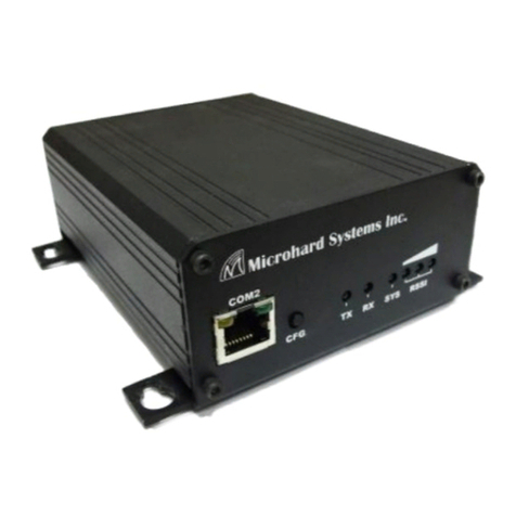
Microhard Systems IPn4Gii User manual

IPn4Gii / IPn3Gii
IPn4Gii 4G/LTE Dual Ethernet/Serial/USB Gateway
IPn3Gii 3G/HSPA+ Dual Ethernet/Serial/USB Gateway
Document: IPn3Gii+IPn4Gii Operating Manual.v1.3.pdf
FW: v1.2.0 Build 1038
Operating Manual
May 2015
150 Country Hills Landing NW
Calgary, Alberta
Canada T3K 5P3
Phone: (403) 248-0028
Fax: (403) 248-2762
www.microhardcorp.com

© Microhard Systems Inc. 2
Important User Information
Warranty
Microhard Systems Inc. warrants that each product will be free of defects in material and workmanship for a
period of one (1) year for its products. The warranty commences on the date the product is shipped by Micro-
hard Systems Inc. Microhard Systems Inc.’s sole liability and responsibility under this warranty is to repair or
replace any product which is returned to it by the Buyer and which Microhard Systems Inc. determines does
not conform to the warranty. Product returned to Microhard Systems Inc. for warranty service will be shipped
to Microhard Systems Inc. at Buyer’s expense and will be returned to Buyer at Microhard Systems Inc.’s ex-
pense. In no event shall Microhard Systems Inc. be responsible under this warranty for any defect which is
caused by negligence, misuse or mistreatment of a product or for any unit which has been altered or modified
in any way. The warranty of replacement shall terminate with the warranty of the product.
Warranty Disclaims
Microhard Systems Inc. makes no warranties of any nature of kind, expressed or implied, with respect to the
hardware, software, and/or products and hereby disclaims any and all such warranties, including but not lim-
ited to warranty of non-infringement, implied warranties of merchantability for a particular purpose, any inter-
ruption or loss of the hardware, software, and/or product, any delay in providing the hardware, software, and/
or product or correcting any defect in the hardware, software, and/or product, or any other warranty. The Pur-
chaser represents and warrants that Microhard Systems Inc. has not made any such warranties to the Pur-
chaser or its agents MICROHARD SYSTEMS INC. EXPRESS WARRANTY TO BUYER CONSTITUTES MICROHARD
SYSTEMS INC. SOLE LIABILITY AND THE BUYER’S SOLE REMEDIES. EXCEPT AS THUS PROVIDED, MICROHARD
SYSTEMS INC. DISCLAIMS ALL WARRANTIES, EXPRESS OR IMPLIED, INCLUDING ANY WARRANTY OF MER-
CHANTABILITY OR FITNESS FOR A PARTICULAR PROMISE.
MICROHARD SYSTEMS INC. PRODUCTS ARE NOT DESIGNED OR INTENDED TO BE USED IN
ANY LIFE SUPPORT RELATED DEVICE OR SYSTEM RELATED FUNCTIONS NOR AS PARTOF
ANY OTHER CRITICAL SYSTEM AND ARE GRANTED NO FUNCTIONAL WARRANTY.
Indemnification
The Purchaser shall indemnify Microhard Systems Inc. and its respective directors, officers, employees, suc-
cessors and assigns including any subsidiaries, related corporations, or affiliates, shall be released and dis-
charged from any and all manner of action, causes of action, liability, losses, damages, suits, dues, sums of
money, expenses (including legal fees), general damages, special damages, including without limitation,
claims for personal injuries, death or property damage related to the products sold hereunder, costs and de-
mands of every and any kind and nature whatsoever at law.
IN NO EVENT WILL MICROHARD SYSTEMS INC. BE LIABLE FOR ANY INDIRECT, SPECIAL, CONSEQUENTIAL,
INCIDENTAL, BUSINESS INTERRUPTION, CATASTROPHIC, PUNITIVE OR OTHER DAMAGES WHICH MAY BE
CLAIMED TO ARISE IN CONNECTION WITH THE HARDWARE, REGARDLESS OF THE LEGAL THEORY BEHIND
SUCH CLAIMS, WHETHER IN TORT, CONTRACT OR UNDER ANY APPLICABLE STATUTORY OR REGULATORY
LAWS, RULES, REGULATIONS, EXECUTIVE OR ADMINISTRATIVE ORDERS OR DECLARATIONS OR OTHERWISE,
EVEN IF MICROHARD SYSTEMS INC. HAS BEEN ADVISED OR OTHERWISE HAS KNOWLEDGE OF THE POSSIBIL-
ITY OF SUCH DAMAGES AND TAKES NO ACTION TO PREVENT OR MINIMIZE SUCH DAMAGES. IN THE EVENT
THAT REGARDLESS OF THE WARRANTY DISCLAIMERS AND HOLD HARMLESS PROVISIONS INCLUDED ABOVE
MICROHARD SYSTEMS INC. IS SOMEHOW HELD LIABLE OR RESPONSIBLE FOR ANY DAMAGE OR INJURY, MI-
CROHARD SYSTEMS INC.'S LIABILITY FOR ANYDAMAGES SHALL NOT EXCEED THE PROFIT REALIZED BY MI-
CROHARD SYSTEMS INC. ON THE SALE OR PROVISION OF THE HARDWARE TO THE CUSTOMER.
Proprietary Rights
The Buyer hereby acknowledges that Microhard Systems Inc. has a proprietary interest and intellectual prop-
erty rights in the Hardware, Software and/or Products. The Purchaser shall not (i) remove any copyright, trade
secret, trademark or other evidence of Microhard Systems Inc.’s ownership or proprietary interest or confiden-
tiality other proprietary notices contained on, or in, the Hardware, Software or Products, (ii) reproduce or mod-
ify any Hardware, Software or Products or make any copies thereof, (iii) reverse assemble, reverse engineer or
decompile any Software or copy thereof in whole or in part, (iv) sell, transfer or otherwise make available to
others the Hardware, Software, or Products or documentation thereof or any copy thereof, except in accor-
dance with this Agreement.
© Microhard Systems Inc. 3
Important User Information (continued)
About This Manual
It is assumed that users of the products described herein have either system integration or
design experience, as well as an understanding of the fundamentals of radio communications.
Throughout this manual you will encounter not only illustrations (that further elaborate on the
accompanying text), but also several symbols which you should be attentive to:
Caution or Warning
Usually advises against some action which could result in undesired or
detrimental consequences.
Point to Remember
Highlights a key feature, point, or step which is noteworthy. Keeping
these in mind will simplify or enhance device usage.
Tip
An idea or suggestion to improve efficiency or enhance usefulness.
Information
Information regarding a particular technology or concept.

© Microhard Systems Inc. 4
Important User Information (continued)
Please Note: These are only sample labels; different products contain different identifiers. The actual identifiers should be seen on
your devices if applicable. S'il vous plaît noter: Ce sont des exemples d'étiquettes seulement; différents produits contiennent des
identifiants différents. Les identifiants réels devrait être vu sur vos périphériques le cas échéant.
Regulatory Requirements / Exigences Réglementaires
To satisfy FCC RF exposure requirements for mobile transmitting devices, a separation distance of 23cm or more should be maintained
between the antenna of this device and persons during device operation. To ensure compliance, operations at closer than this distance is not
recommended. The antenna being used for this transmitter must not be co-located in conjunction with any other antenna or transmitter.
WARNING
MAXIMUM EIRP
FCC Regulations allow up to 36dBm Effective Isotropic Radiated Power (EIRP). Therefore, the sum of the transmitted power (in dBm), the
cabling loss and the antenna gain cannot exceed 36dBm.
WARNING
EQUIPMENT LABELING / ÉTIQUETAGE DE L'ÉQUIPEMENT
This device has been modularly approved. The manufacturer, product name, and FCC and Industry Canada identifiers of this product must
appear on the outside label of the end-user equipment.
WARNING
SAMPLE LABEL REQUIREMENT / EXIGENCE D'ÉTIQUETTE :
IPn3Gii IPn4Gii
Pour satisfaire aux exigences de la FCC d'exposition RF pour les appareils mobiles de transmission, une distance de séparation de 23cm ou
plus doit être maintenue entre l'antenne de cet appareil et les personnes au cours de fonctionnement du dispositif. Pour assurer le respect,
les opérations de plus près que cette distance n'est pas recommandée. L'antenne utilisée pour ce transmetteur ne doit pas être co-localisés
en conjonction avec toute autre antenne ou transmetteur.
Réglementation de la FCC permettra à 36dBm Puissance isotrope rayonnée équivalente (EIRP). Par conséquent, la somme de la puissance
transmise (en dBm), la perte de câblage et le gain d'antenne ne peut pas dépasser 36dBm.
Ce dispositif a été approuvé de façon modulaire. Le fabricant, le nom du produit, et la FCC et de l'Industrie du Canada identifiants de ce
produit doit figurer sur l'étiquette à l'extérieur de l'équipement de l'utilisateur final.
FCCID: XPYLISAU230
IC: 8595A-LISAU230
This device complies with Part 15 of the FCC Rules.
Operation is subject to the following two conditions:
(1) this device may not cause harmful interference,
and (2) this device must accept any interference
received including interference that may cause
undesired operation.
FCCID: R17LN930
IC: 5131A-LN930
This device complies with Part 15 of the FCC Rules.
Operation is subject to the following two conditions:
(1) this device may not cause harmful interference,
and (2) this device must accept any interference
received including interference that may cause
undesired operation.
FCCID: R5Q-TOBYL100
IC: 8595B-TOBYL100
This device complies with Part 15 of the FCC Rules.
Operation is subject to the following two conditions:
(1) this device may not cause harmful interference,
and (2) this device must accept any interference
received including interference that may cause
undesired operation.
IPn4Gii - Verizon

© Microhard Systems Inc. 5
CSA Class 1 Division 2 Option
CSA Class 1 Division 2 is Available Only on Specifically Marked Units
If marked this for Class 1 Division 2 –then this product is available for use in Class 1 Division 2, in the indicated Groups on the
product.
In such a case the following must be met:
The transceiver is not acceptable as a stand-alone unit for use in hazardous locations. The transceiver must be mounted within a
separate enclosure, which is suitable for the intended application. Mounting the units within an approved enclosure that is certified
for hazardous locations, or is installed within guidelines in accordance with CSA rules and local electrical and fire code, will ensure
a safe and compliant installation.
The antenna feed line; DC power cable and interface cable must be routed through conduit in accordance with the National
Electrical Code.
Do not connect or disconnect equipment unless power has been switched off or the area is known to be non-hazardous.
Installation, operation and maintenance of the transceiver should be in accordance with the transceiver’s installation manual, and
the National Electrical Code.
Tampering or replacement with non-factory components may adversely affect the safe use of the transceiver in hazardous
locations, and may void the approval.
The wall adapters supplied with your transceivers are NOT Class 1 Division 2 approved, and therefore, power must be supplied to
the units using the screw-type or locking type connectors supplied from Microhard Systems Inc. and a Class 1 Division 2 power
source within your panel.
If you are unsure as to the specific wiring and installation guidelines for Class 1 Division 2 codes, contact CSA International.
CSA Classe 1 Division 2 est disponible uniquement sur les unités particulièrement
marquées
Si marqué cette Classe 1 Division 2 - alors ce produit est disponible pour une utilisation en Classe 1 Division 2 , dans les groupes
indiqués sur le produit .
Dans un tel cas, la suivante doit être remplie:
L'émetteur-récepteur n'est pas acceptable comme une unité autonome pour une utilisation dans des endroits dangereux .
L'émetteur-récepteur doit être monté dans un boîtier séparé , qui est approprié pour l'application envisagée. Montage des unités
dans une enceinte approuvée qui est certifié pour les emplacements dangereux , ou est installé à l'intérieur des lignes directrices ,
conformément aux règles de la CSA et le code électrique local et le feu , assurera une installation sûre et conforme .
La ligne d'alimentation d'antenne , câble d'alimentation CC et le câble d'interface doivent être acheminés à travers le conduit en
conformité avec le National Electrical Code .
Ne pas connecter ou déconnecter l'équipement que l'alimentation est coupée ou que la zone est connue pour être non
dangereux .
Installation, l'exploitation et la maintenance de l'émetteur-récepteur doivent être en conformité avec le manuel d'installation de
l'émetteur-récepteur , et le National Electrical Code .
Falsification ou le remplacement des composants non - usine peut nuire à l'utilisation sécuritaire de l'émetteur-récepteur dans des
endroits dangereux , et peut annuler l'approbation .
Les adaptateurs muraux fournis avec les émetteurs-récepteurs sont PAS classe 1, division 2 ont approuvé , et par conséquent,
doit être alimenté pour les unités à l'aide des connecteurs de type vis ou verrouillage fournies par Microhard Systems Inc. et une
Division 2 source d'alimentation de classe 1 au sein de votre panneau .
Si vous n'êtes pas sûr de l' installation et de câblage des lignes directrices spécifiques pour la classe 1 Division 2 codes ,
communiquer avec la CSA International.

© Microhard Systems Inc. 6
Revision History
Revision Description Initials Date
0.0 Preliminary. PEH Mar 2014
1.0 First Release. Based on Firmware v1.2.0 Build 1008 PEH July 2014
1.1 Updated to reflect default IP change to 192.168.168.1 for all unit
types. v1.2.0 Build 1015.
PEH Sept 2014
1.2 Updated to align with firmware version 1.2.0 Build 1016. Added Mul-
tiWAN, updated Carrier Dual SIM. Added TAIP, Added Websocket,
Updated I/O, Updated screenshots throughout, misc corrections.
PEH Sept 2014
1.21 Updated to notify users must configure firewall and/or appropriate
rules to use IP-Passthrough.
PEH Oct 2014
1.22 Removed AT+CMGS (Not currently Supported), Added Current Con-
sumption.
PEH Feb 2015
1.3 Updated to align with firmware version v1.2.0-r1038 PEH May 2015

© Microhard Systems Inc. 7
Table of Contents
1.0 Overview .........................................................................................................10
1.1 Performance Features................................................................................................... 10
1.2 Specifications................................................................................................................ 11
1.3 RF Performance............................................................................................................ 13
2.0 QUICK START.................................................................................................15
2.1 Installing the SIM Card.................................................................................................. 15
2.2 Getting Started with Cellular.......................................................................................... 15
3.0 Hardware Features.........................................................................................19
3.1 IPnXGii ......................................................................................................................... 19
3.1.1 IPnXGii Mechanical Drawings.............................................................................. 20
3.1.2 IPnXGii Connectors & Indicators.......................................................................... 21
3.1.2.1 Front...................................................................................................... 21
3.1.2.2 Rear...................................................................................................... 22
4.0 Configuration..................................................................................................23
4.0 Web User Interface...................................................................................................... 23
4.0.1 Logon Window..................................................................................................... 24
4.1 System......................................................................................................................... 25
4.1.1 Summary............................................................................................................. 25
4.1.2 Settings............................................................................................................... 26
Host Name .......................................................................................................... 26
Console Timeout.................................................................................................. 26
Date/Time............................................................................................................ 27
NTP Server Settings............................................................................................ 28
4.1.3 Services .............................................................................................................. 29
SSH..................................................................................................................... 29
Telnet.................................................................................................................. 29
HTTP/HTTPS ...................................................................................................... 29
4.1.4 Keepalive............................................................................................................. 30
4.1.5 Maintenance........................................................................................................ 32
Firmware Upgrade............................................................................................... 32
Reset to Default................................................................................................... 32
Backup & Restore Configurations ........................................................................ 33
4.1.6 Reboot................................................................................................................. 34
4.2 Network ....................................................................................................................... 35
4.2.1 Summary............................................................................................................. 35
4.2.2 LAN..................................................................................................................... 36
4.2.3 WAN.................................................................................................................... 39
4.2.4 DHCP (MAC Binding) .......................................................................................... 41
4.2.5 DDNS.................................................................................................................. 42
4.2.6 Routes................................................................................................................. 43
4.2.6 Ports (Switch)...................................................................................................... 44
4.2.7 Device List........................................................................................................... 44

© Microhard Systems Inc. 8
Table of Contents
4.3 Carrier.......................................................................................................................... 45
4.3.1 Status.................................................................................................................. 45
4.3.2 Settings............................................................................................................... 46
Dual Cards Management..................................................................................... 47
4.3.3 SMS.................................................................................................................... 51
4.3.4 SMS Config......................................................................................................... 52
4.3.5 Data Usage ......................................................................................................... 55
4.4 Firewall ....................................................................................................................... 58
4.4.1 Summary............................................................................................................. 58
4.4.2 General ............................................................................................................... 59
4.4.3 Port Forwarding................................................................................................... 61
4.4.4 MAC-IP List......................................................................................................... 63
4.4.5 Rules................................................................................................................... 65
4.4.6 Firewall Default.................................................................................................... 67
4.5 VPN ............................................................................................................................ 68
4.5.1 Summary............................................................................................................. 68
4.5.2 Gateway to Gateway............................................................................................ 69
4.5.3 Client to Gateway (L2TP Client)........................................................................... 74
4.5.4 GRE.................................................................................................................... 76
4.5.5 L2TP Users ......................................................................................................... 79
4.5.6 Certificates .......................................................................................................... 80
4.6 MultiWAN..................................................................................................................... 81
4.6.1 Status.................................................................................................................. 81
4.6.2 Settings............................................................................................................... 82
4.7 Serial............................................................................................................................ 84
4.7.1 Summary............................................................................................................. 84
4.7.2 RS232/Console/RS485 Settings .......................................................................... 85
Data Baud Rate................................................................................................... 86
IP Protocol Config................................................................................................ 89
TCP Client ...................................................................................................... 89
TCP Server..................................................................................................... 89
TCP Client/Server........................................................................................... 90
UDP Point-to-Point.......................................................................................... 90
UDP Point-to-Multipoint (P)............................................................................. 90
UDP Point-to-Multipoint (MP) .......................................................................... 91
UDP Multipoint-to-Multipoint............................................................................ 91
SMTP Client.................................................................................................... 92
PPP................................................................................................................ 92
GPS Transparent Mode .................................................................................. 93
4.8 USB.............................................................................................................................. 94
4.8.1 Summary............................................................................................................. 94
4.8.2 Serial................................................................................................................... 95
4.8.3 NDIS ................................................................................................................... 96
4.9 I/O ................................................................................................................................ 97
4.9.1 Summary............................................................................................................. 97

© Microhard Systems Inc. 9
Table of Contents
4.10 GPS.............................................................................................................................. 99
4.10.1 Location............................................................................................................. 99
4.10.2 Settings.............................................................................................................. 100
4.10.3 Report................................................................................................................ 101
4.10.4 GPSGate............................................................................................................ 103
4.10.5Recorder............................................................................................................. 106
4.10.6 Load Record....................................................................................................... 107
4.10.7 TAIP................................................................................................................... 110
4.11 Applications................................................................................................................ 112
4.11.1 Modbus.............................................................................................................. 112
4.11.1.1 TCP Modbus........................................................................................ 112
4.11.1.2 Serial (COM) Modbus........................................................................... 114
4.11.1.3 Modbus Data Map................................................................................ 115
4.11.2 Netflow Report................................................................................................... 116
4.11.3 Local Monitor ..................................................................................................... 118
4.11.4 Event Report...................................................................................................... 119
4.11.4.1 Configuration ....................................................................................... 119
4.11.4.2 Message Structure............................................................................... 120
4.11.4.2 Message Payload................................................................................. 120
4.11.5 Websocket......................................................................................................... 122
4.11.6 Diagnostics........................................................................................................ 124
Network Ping...................................................................................................... 124
Network Trace Route ......................................................................................... 124
4.12 Admin .......................................................................................................................... 125
4.12.1 Users................................................................................................................. 125
4.12.2 Authentication (RADIUS).................................................................................... 127
4.12.3 NMS .................................................................................................................. 128
4.12.4 SNMP................................................................................................................ 132
4.12.5 Discovery........................................................................................................... 135
4.12.6 Power Saving Modes ......................................................................................... 136
4.12.7 Logout................................................................................................................ 137
5.0 AT Command Line Interface...........................................................................138
5.1 AT Command Overview.............................................................................................. 138
5.1.1 Serial Port.......................................................................................................... 138
5.1.2 Telnet................................................................................................................. 139
5.2 AT Command Syntax.................................................................................................. 140
5.3 Supported AT Commands.......................................................................................... 141
Appendices ..........................................................................................................174
Appendix A: Serial Interface.................................................................................................. 174
Appendix B: IP-Passthrough Example................................................................................... 175
Appendix C: Port Forwarding Example.................................................................................. 177
Appendix D: VPN (Site to Site) Example ............................................................................... 179
Appendix E: Firewall Rules Example..................................................................................... 181
Appendix F: Troubleshooting................................................................................................. 183

© Microhard Systems Inc. 10
1.0 Overview
The IPn4Gii & IPn3Gii products are high-performance Cellular Dual Ethernet/Serial/USB
Gateways, equipped with dual RJ45 Ethernet Ports, dual SIM capability, 8x Programmable
Analog I/O, Optional Standalone GPS, and up to three serial communication ports. One each
of RS232, RS485 and a RS232 Console port, which can be used as an additional data port.
The IPnXGii utilizes the cellular infrastructure to provide network access to wired devices any-
where cellular coverage is supported by a cellular carrier. The IPn3Gii supports up to 21Mbps
downloads, when connected to a HSPA+ enabled carrier, or global fallback to 3G/Edge net-
works for areas without HSPA+. The IPn4Gii supports 4G/LTE connections with blazing fast
speeds.
Providing reliable Cellular Ethernet bridge functionality as well gateway service for most
equipment types which employ an RS232, RS422, or RS485 interface, the IPnXGii can be
used in a limitless types of applications such as:
1.1 Performance Features
Key performance features of the IPnXGii include:
High-speed backbone
IP video surveillance
Voice over IP (VoIP)
Facilitating internetwork
wireless communications
Legacy network/device
migration
SCADA (PLC’s, Modbus,
Hart)
Fast, reliable connection speeds to 4G, 3G, LTE, and HSPA Networks (varies by
model)
8x Programmable Analog/Digital Inputs OR up to 8 Digital Outputs
DMZ and Port Forwarding
Dual 10/100 Ethernet Ports (WAN/LAN)
Standalone GPS (TCP Server/UDP/SMTP Reporting)
User interface via local console, telnet, web browser
Compatibility with virtually all PLCs, RTUs, and serial devices through either
RS232, RS422, or RS485 interfaces.
Local & remote wireless firmware upgradable
User configurable Firewall with IP/MAC ACL
IP/Sec secure VPN and GRE Tunneling
Industrial Temperature Rating (-40oC to +85oC)

© Microhard Systems Inc. 11
1.0 Overview
1.2 Specifications
IPn3Gii
IPn3Gii Supported Bands: UMTS/HSPA FDD Bands [MHz] - Six band
Band I (2100MHz), Band II (1900MHz), Band IV (1700MHz), Band V
(850MHz), Band VI (800MHz), Band VIII (900Hz)
3GPP Release 7
5.76 Mb/s uplink, 21.1 Mb/s downlink
or 5.76 Mb/s uplink, 7.2 Mb/s downlink
IPn3Gii Data Features: HSDPA cat 14, up to 21.1 Mb/s DL
GPRS multi-slot class 125, coding scheme CS1-CS4, up to 85.6 kb/s DL/UL
EDGE multi-slot class 125, coding scheme MCS1-MCS9, up to 236.8 kb/s DL/UL
CSD GSM max 9.6 kb/s
UMTS max 64 kb/s
IPn3Gii TX Power: WCDMA/HSDPA/HSUPA Power Class
· Power Class 3 (24 dBm) for WCDMA/HSDPA/HSUPA mode
GSM/GPRS Power Class
· Power Class 4 (33 dBm) for GSM/E-GSM bands
· Power Class 1 (30 dBm) for DCS/PCS bands
EDGE Power Class
· Power Class E2 (27 dBm) for GSM/E-GSM bands
· Power Class E2 (26 dBm) for DCS/PCS bands
IPn4Gii
IPn4Gii Supported Bands: LTE FDD (Bands 1-5,7,8,13,17,18,19,20)
UMTS | DC-HSPA+ (Bands 1,2,4,5,8)
GSM | GPRS | EDGE (Bands 2,3,5,8)
3GPP Protocol Stack Release 9
IPn4Gii Data Features: LTE: DL 100 Mbps, UL 50 Mbps
HSPA+: DL 42 Mbps, UL 5.7 Mbps
HSPA+: DL 21 Mbps, UL 5.7 Mbps
WCDMA: DL/UL 384 kbps
EDGE Class 33: DL/UL 236.8 kbps
GPRS Class 33: DL/UL 85.6kbps
General
Serial Interface: RS232, RS485, RS422
Serial Baud Rate: 300bps to 921kbps
USB: USB 2.0
USB Console Port
USB to Serial Data Routing
USB to Ethernet Data Routing (NDIS)
USB OTG (Host)
Current Consumption:
(@12VDC)
Model AVG Serial
Data AVG Ethernet
Data TX Max. Peak
IPn3Gii 130mA 140mA 215mA
IPn4Gii 130mA 145mA 250mA

© Microhard Systems Inc. 12
1.0 Overview
General Specifications (Continued)
Ethernet: 2 x 10/100 BaseT, Auto - MDI/X, IEEE 802.3
I/O: 8x Programmable Analog/Digital Inputs or up to 8x Digital Outputs
60mA current sink on open drain
SIM Card: Dual: 1.8 / 3.0V
PPP Characteristics: Dial on Demand/Idle Time
Network Protocols: TCP, UDP, TCP/IP, TFTP, ARP, ICMP, DHCP, HTTP, HTTPS*, SSH*, SNMP,
FTP, DNS, Serial over IP, QoS
Management: Local Serial Console, Telnet, WebUI, SNMP, FTP &
Wireless Upgrade, RADIUS authentication, IPsec VLAN
Diagnostics: Temperature, RSSI, remote diagnostics
Input Voltage: 7-30 VDC
Power over Ethernet: Passive PoE on Ethernet Port (WAN)
GPS: Sensitivity: - Autonomous acquisition: -145 dBm
- Tracking Sensitivity: -158 dBm (50% valid fixes)
Position Accuracy: - Tracking L1, CA code
- 12 Channels
- Max. update rate 1 Hz
Error calculated location less than 11.6 meters 67% of the time, and
less than 24.2 meters 95% of the time.
Environmental
Operation Temperature: -40oF(-40oC) to 185oF(85oC)
Humidity: 5% to 95% non-condensing
Mechanical
Dimensions: 2.21” (56mm) X 3.85” (97mm) X 1.46” (37mm)
Weight: Approx. 245 grams
Connectors: Antenna(s): CELL, DIV, GPS: SMA Female
ANT3: RP-SMA Female
Data, etc: Data: DE-9 Female (Front RS232)
Ethernet : 2x RJ-45
GPS Antenna Requirements:
- Frequency Range: 1575.42 MHz (GPS L1 Band)
- Bandwidth: +/- 2 MHz
- Total NF < 2.5dB
- Impedance 50ohm
- Amplification (Gain applied to RF connector): 19dB to 23dB
- Supply voltage 1.5V to 3.05V
- Current consumption - Typical 20mA (100mA max)
- Cellular Power Antenna Rejection + Isolation:
- 824 - 915 MHz > 10dB
- 1710 - 1785 MHz > 19dB
- 1850 - 1980 MHz > 23dB

© Microhard Systems Inc. 13
1.0 Overview
1.3 IPn3GiiRF Performance
Frequency Range Min. (MHz) Max. (MHz) Remarks
GSM 850 Uplink 824 849 Module transmit
Downlink 869 894 Module receive
E-GSM 900 Uplink 880 915 Module transmit
Downlink 925 960 Module receive
DCS 1800 Uplink 1710 1785 Module transmit
Downlink 1805 1880 Module receive
PCS1900 Uplink 1850 1910 Module transmit
Downlink 1930 1990 Module receive
UMTS 800 (band VI) Uplink 830 840 Module transmit
Downlink 875 885 Module receive
UMTS 850 (band V) Uplink 824 849 Module transmit
Downlink 869 894 Module receive
UMTS 900 (band VIII) Uplink 880 915 Module transmit
Downlink 925 960 Module receive
UMTS 1700 (band VIII) Uplink 1710 1755 Module transmit
Downlink 2110 2155 Module receive
UMTS 1900 (band II) Uplink 1850 1910 Module transmit
Downlink 1930 1990 Module receive
Uplink 1920 1980 Module transmit
UMTS 2100 (band 1) Downlink 2110 2170 Module receive
Table 1-1: IPn3Gii Operating RF Frequency Bands
Receiver Input Sensitivity Min. (dBm) Typ. (dBm) Max. (dBm) Remarks
GSM 850 / E-GSM 900 -102.0 -110.0 Downlink RF level @ BER Class II < 2.4%
DCS 1800 / PCS 1900 -102.0 -109.0 Downlink RF level @ BER Class II < 2.4%
UMTS 800 (band VI) -106.7 -111.0 Downlink RF level for RMC @ BER < 0.1%
UMTS 850 (band V) -104.7 -112.0 Downlink RF level for RMC @ BER < 0.1%
UMTS 900 (band VIII) -103.7 -111.0 Downlink RF level for RMC @ BER < 0.1%
UMTS 1700 (band VIII) -106.7 -111.0 Downlink RF level for RMC @ BER < 0.1%
UMTS 1900 (band II) -104.7 -111.0 Downlink RF level for RMC @ BER < 0.1%
UMTS 2100 (band 1) -106.7 -111.0 Downlink RF level for RMC @ BER < 0.1%
Condition: 50 Ωsource
Table 1-2: IPn3Gii Receiver sensitivity performance

© Microhard Systems Inc. 14
1.0 Overview
1.3 IPn3GiiRF Performance (continued…)
Table 1-3: IPn3Gii Transmitter maximum output power
Maximum Output
Power Min. Typ.
(dBm) Max. Remarks
GSM 850 / E-GSM 900
32.5 Uplink burst RF power for GSM or GPRS 1-slot TCH at PCL 5 or Gamma 3
32.5 Uplink burst RF power for GPRS 2-slot TCH at Gamma 3
31.7 Uplink burst RF power for GPRS 3-slot TCH at Gamma 3
30.5 Uplink burst RF power for GPRS 4-slot TCH at Gamma 3
27.0 Uplink burst RF power for EDGE 8PSK 1-slot TCH at PCL 8 or Gamma 6
27.0 Uplink burst RF power for EDGE 8PSK 2-slot TCH at Gamma 6
26.2 Uplink burst RF power for EDGE 8PSK 3-slot TCH at Gamma 6
25.0 Uplink burst RF power for EDGE 8PSK 4-slot TCH at Gamma 6
29.5 Uplink burst RF power for GSM or GPRS 1-slot TCH at PCL 0 or Gamma 3
DCS 1800 / PCS 1900
29.5 Uplink burst RF power for GPRS 2-slot TCH at Gamma 3
28.7 Uplink burst RF power for GPRS 3-slot TCH at Gamma 3
27.5 Uplink burst RF power for GPRS 4-slot TCH at Gamma 3
26.0 Uplink burst RF power for EDGE 8PSK 1-slot TCH at PCL 2 or Gamma 5
26.0 Uplink burst RF power for EDGE 8PSK 2-slot TCH at Gamma 5
25.2 Uplink burst RF power for EDGE 8PSK 3-slot TCH at Gamma 5
24.0 Uplink burst RF power for EDGE 8PSK 4-slot TCH at Gamma 5
UMTS 800 (band VI) 23.0 Uplink continuous RF power for RMS at maximum power
UMTS 850 (band V) 23.0 Uplink continuous RF power for RMS at maximum power
UMTS 900 (band VIII) 23.0 Uplink continuous RF power for RMS at maximum power
UMTS 1700 (band VIII) 23.0 Uplink continuous RF power for RMS at maximum power
UMTS 1900 (band II) 23.0 Uplink continuous RF power for RMS at maximum power
UMTS 2100 (band 1) 23.0 Uplink continuous RF power for RMS at maximum power
Condition for all parameters: 50 Ωoutput load
Condition for GPRS/EDGE multi-slot output power: Multi-Slot Power Reduction profile 2

© Microhard Systems Inc. 15
2.0 Quick Start
This QUICK START guide will walk you through the setup and process required to access the
WebUI configuration window and to establish a basic wireless connection to your carrier.
Note that the units arrive from the factory with the Local Network setting configured as
‘Static’ (IP Address 192.168.168.1, Subnet Mask 255.255.255.0, and Gateway
192.168.168.1), in DHCP server mode. (This is for the LAN Ethernet Adapter on the back of
the IPnXGii unit.
2.1 Installing the SIM Card
Before the IPnXGii can be used on a cellular network a valid SIM Card for your Wireless
Carrier must be installed. Insert the SIM Card into the slot as shown, the top SIM slot is
for SIM1:
2.2 Getting Started with Cellular
Connect the Antenna’s to the applicable ANTENNA jack’s of the IPnXGii.
Connect the power connector to the power adapter and apply power to the unit, the CPU
LED will flash during boot-up, once on solid, proceed to the next step.
SIM Card Slot
To reset to factory
defaults, press and hold
the CFG button for 8
seconds with the IPnXGii
powered up. The LED’s
will flash quickly and the
IP4G will reboot with
factory defaults.
Use the MHS-supplied
power adapter or an
equivalent power source.
The unit can also be powered
via PoE using a MHS PoE
injector.
GPS Antenna
Cellular
Antenna’s
7-30VDC

© Microhard Systems Inc. 16
2.0 Quick Start
Connect A PC configured for DHCP directly to the LAN port of the IPnXGii, using an
Ethernet Cable. If the PC is configured for DHCP it will automatically acquire a IP Address
from the IPnXGii.
Open a Browser Window and enter the IP address 192.168.168.1 into the address bar.
The IPnXGii will then ask for a Username and Password. Enter the factory defaults listed
below.
192.168.168.1
The factory default network
settings:
IP: 192.168.168.1
Subnet: 255.255.255.0
Gateway: 192.168.168.1
The Factory default login:
User name: admin
Password: admin
The factory default login:
User name: admin
Subnet: admin
It is always a good idea to
change the default admin
login for future security.

© Microhard Systems Inc. 17
Once successfully logged in, the System Summary page will be displayed.
As seen above under Carrier Status, the SIM card is installed, but an APN has not been
specified. Setting the APN to auto (default) may provide quick network connectivity, but
may not work with some carriers, or with private APN’s. To set or change the APN, click
on the Carrier > Settings tab and enter the APN supplied by your carrier in the APN field.
Some carriers may also require a Username and Password.
Once the APN and any other required information is entered to connect to your carrier,
click on “Submit”.
Verizon Models do not require a APN and will Auto Connect if a valid SIM card is inserted.
2.0 Quick Start
Auto APN: The IPnXGii will
attempt to detect the carrier
based on the SIM card
installed and cycle through a
list of commonly used APN’s
to provide quick network
connectivity.

© Microhard Systems Inc. 18
On the Carrier > Status Tab, verify that a WAN IP Address has been assigned by your
carrier. It may take a few minutes, so try refreshing the page if the WAN IP Address
doesn’t show up right away. The Activity Status should also show “Connected”.
If you have set a static IP on your PC, you may need to add the DNS Servers shown in
the Carrier Status Menu to you PC to enable internet access.
Congratulations! Your IPnXGii is successfully connected to your Cellular Carrier.
To access devices connected to IPnXGii remotely, one or more of the following must be
configured: IP-Passthrough, Port Forwarding, DMZ. Another option would be to set up a
VPN.
Ensure that all default passwords are changed to limit access to the modem.
For best practices and to limit data charges it is critical to properly set up the firewall.
(Especially important for Public Static IP addresses.)
2.0 Quick Start
Ensure the default
passwords are changed.
Set up appropriate firewall
rules to block unwanted
incoming data.

© Microhard Systems Inc. 19
3.0 Hardware Features
3.1 IPnXGii
The IPnXGii is a fully-enclosed unit ready to be interfaced to external devices.
The IPnXGii Hardware Features Include:
Standard Connectors for:
2 Ethernet Ports (RJ45 - WAN/LAN)
Data Port (RS232/DB9)
COM2 Port (RS232/Console)
4-Pin: MATE-N-LOK Type Connector for Power / I/O 1/2
6-Pin: MATE-N-LOK Type Connector for RS485 Data
10-Pin: MATE-N-LOK Type Connector for RS232 Console / I/O 3-8
Cellular Antenna (SMA Female Antenna Connection x2)
ANT3 Antenna (RP-SMA Female Antenna Connection) (Future)
Status/Diagnostic LED’s for RSSI(x3), Tx, Rx, CELL, CPU
Dual SIM (standard size) Card Slots
CFG Button for factory default / firmware recovery operations
Mounting Holes
Image 3-1: Front View of IPnXGii
Image 3-2: Rear View of IPnXGii

© Microhard Systems Inc. 20
3.0 Hardware Features
3.1.1 Mechanical Drawings
Drawing 3-1: IPnXGii Top View Dimensions
Drawing 3-2: IPnXGii Front View Dimensions
Drawing 3-3: IPnXGii Rear View Dimensions
Note: All dimension units: Millimeter
119.50
9.75
37.00
100.01
2.50
9.75
100.01
108.50
119.50
32.04
13.48
10.48
5.50
4.25
14.50
47.00
20.16
36.58
56.00
71.10
R3.50
Ø7.00
100.01
9.75
37.00
2.50
119.50
This manual suits for next models
1
Table of contents
Other Microhard Systems Gateway manuals

Microhard Systems
Microhard Systems VIP4G User manual

Microhard Systems
Microhard Systems IPN4G User manual

Microhard Systems
Microhard Systems IP-921 User manual

Microhard Systems
Microhard Systems IPN3G User manual

Microhard Systems
Microhard Systems BulletPlus User manual

Microhard Systems
Microhard Systems IPN3G User manual

Microhard Systems
Microhard Systems Nano IP Series User manual

Microhard Systems
Microhard Systems VIP4G User manual