1 Supplementary Operating Manual
4 of 16 BACnet MS/TP Gateway
1 Supplementary Operating Manual
1.1 General
This supplementary operating manual accompanies the installation/operating
manual. All information contained in the installation/operating manual must be
observed.
Table1: Relevant operating manuals
Type series Reference number of the operating/installation
manual
PumpDrive 2 4074.81
1.2 Function
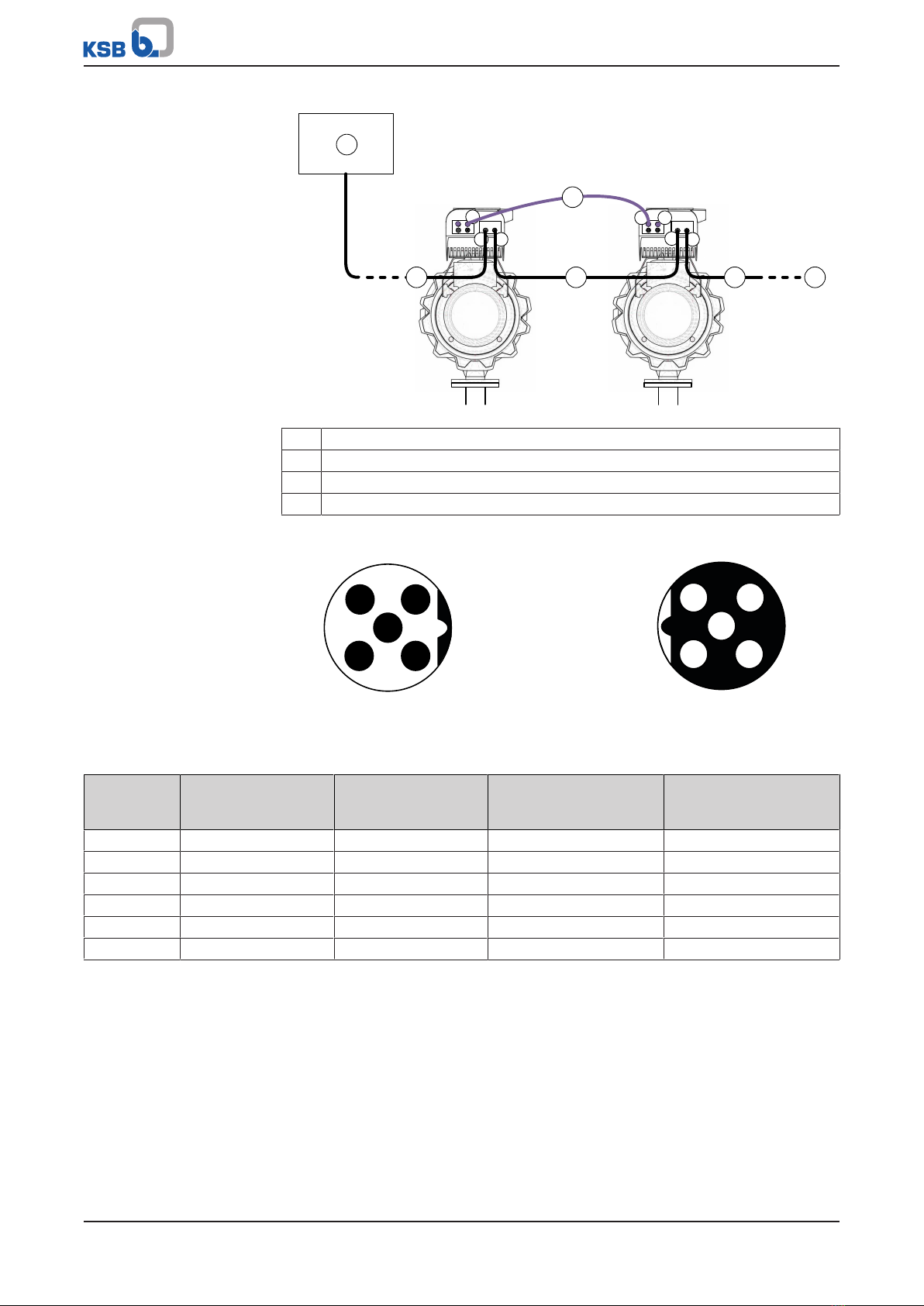
The BACnet MS/TP module is used to connect the frequency inverter to a BACnet MS/
TP network. A BACnet MS/TP module is required for monitoring and open-loop or
closed-loop control purposes for each frequency inverter in single-pump or multiple
pump configurations of up to 2 pump sets.
▪BACnet = Building Automation and Control Networks
▪MS/TP = Master-Slave/Token Passing
Interface The BACnet MS/TP module has a BACnet MS/TP interface.
Communication protocol BACnet MS/TP
Bus terminator External interface EIA-485 (RS 485)
Transmission rate 9600baud, 19200baud, 38400 baud,
57600baud, 115200 baud
Device type B-ASC
Information and downloads on BACnet are available online at http://www.big-
eu.org.
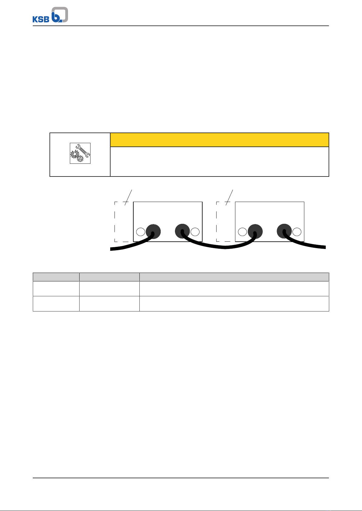
The BACnet MS/TP EIA-485 network cable should have the following properties:
▪Flexible
▪Shielded
▪Twisted wires for the data line
▪The wave impedance should be between 100 and 130 ohms.
▪For more details, see ANSI/ASHRAE standard 135, “Physical Layer” section.
Information on BACnet MS/TP and downloads for BACnet MS/TP are available online
at www.bacnet.org. For additional accessories for the BACnet MS/TP module (i.e.
M12 connectors and terminating resistors), see the type series booklet.
EDE lists
KSB provides an EDE file on the KSB web site for exchanging PumpDrive-specific
BACnet information. The EDE lists document all inbound and outbound objects with
the associated defined properties.
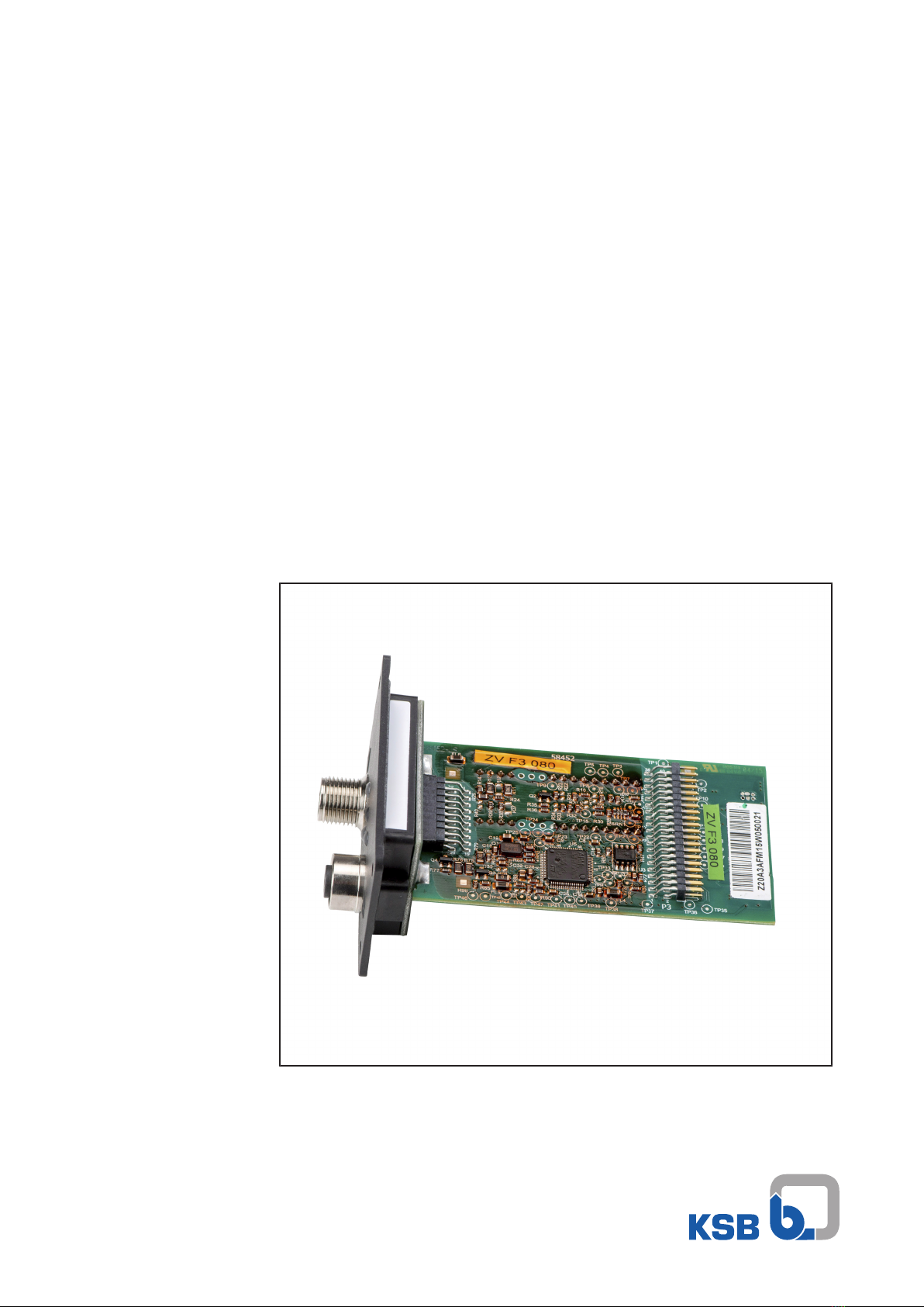
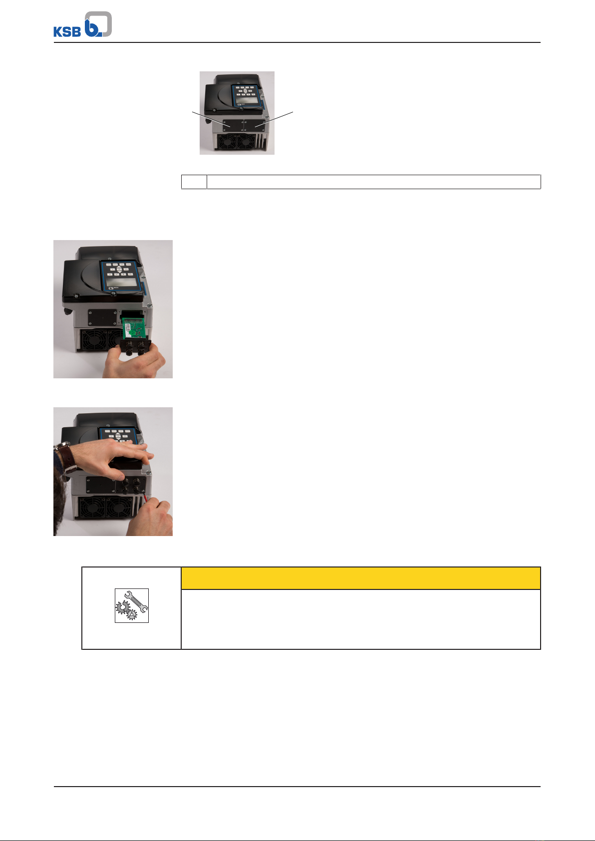
1.3 Field bus module connections
The field bus modules are plug-in modules.