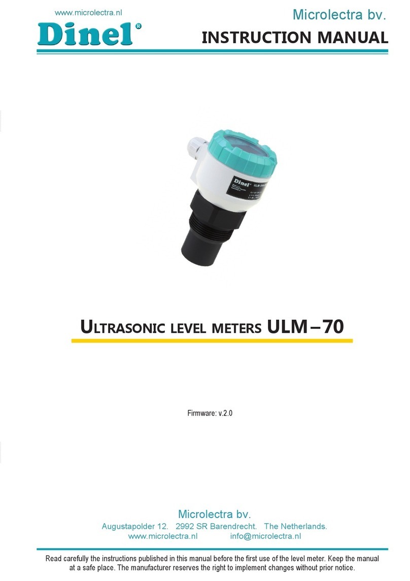
Microlectra Dinel ULM-70 User manual

Read carefully the instructions published in this manual before the rst use of the level meter. Keep the manual
at a safe place. The manufacturer reserves the right to implement changes without prior notice.
INSTRUCTION MANUAL
ultrasonic level meters ulm – 70
Firmware: v.2.0


TABLE OF CONTENTS
1 . Measuring principle........................................................................................................................................... 3
2 . Range of applications........................................................................................................................................ 3
3 . Variants of sensors............................................................................................................................................ 3
4 . Dimensional drawings ...................................................................................................................................... 4
5 . Installation and putting into operation....................................................................................................... 4
6. Installation instructions .................................................................................................................................. 5
7. Electrical connection ......................................................................................................................................... 9
8. Examples of ULM-70 connection..................................................................................................................... 10
8.1 . Wiring diagram of the level meter with current output and PDU unit ................................................ 10
8.2 . WiringdiagramofthelevelmeterwithcurrentoutputandPDUunit .............................................
in versions for explosive areas ................................................................................................................... 11
8 .3 . WiringdiagramofthelevelmeterwithcurrentoutputandMGUunit............................................... 13
8 .4 . WiringdiagramofthelevelmeterwithModbus/RS485andMGUunit............................................ 13
8 .5 . WiringdiagramofthelevelmeterwithModbus/RS485andPDUunit ............................................. 13
9 . Set-up elements ................................................................................................................................................. 14
10. Status signalization ......................................................................................................................................... 14
11 . Operation and setting .................................................................................................................................... 15
10.1 . Basicconguration................................................................................................................................... 15
10.2 . Servicesettings ......................................................................................................................................... 18
10 .3 . Additionalfunctions................................................................................................................................. 20
12. HART® communication protocol ................................................................................................................... 22
13. Modbus® communication protocol .............................................................................................................. 23
14 . Order code......................................................................................................................................................... 23
15 . Accessories ........................................................................................................................................................ 23
16 . Safety, protection, compatibility and explosion proof........................................................................... 24
17 . Use, manipulation and maintenance ......................................................................................................... 24
18 . Marking of labels ............................................................................................................................................. 25
19 . Menu structure ................................................................................................................................................ 27
20 . Specications.................................................................................................................................................... 28
21 . Packing, shipping and storage...................................................................................................................... 30

4
© Dinel,s.r.o.ULM–70
1 . MEASURING PRINCIPLE
UltrasoniclevelmeterULM®is a compact measuring device consisting of two parts - main level
meter(thebodywithmeasuringelectronics)anddisplaymodule.Usingtheelectroacoustic
converter, the level meters transmit the sequence of ultrasonic pulses that spread towards the
surfacelevel.Theconverterrecuperatesreectedacousticwavesthataresubsequentlypro-
cessedintheelectronicmodule.Theintelligentevaluationblockltersoutinterferingsignals,
comparesthecleanedreceivedsignalwiththefalsereectionmap(e.g.frommixers,ladders,
reinforcementetc.)andselectsasuitablereection(echo).Basedontheperiodduringwhich
theindividualpulsesspreadtowardsthesurfacelevelandbackandbasedonthemeasured
temperatureinthetank,theinstantdistancetothesurfaceleveliscalculated.Accordingtothe
levelheight,thelevelmeteroutputissetandthemeasuredvalueisdisplayedonthedisplay.
2 . RANGE OF APPLICATIONS
For continuous non-contact level measurement of liquids (water solutions, sewerage water,
etc.),mashandpastematerials(sediments,sticks,resinsetc.)inclosedoropenvessels,sumps,
reservoirsandopenchannels.Incasethelevelofbulk-solidmaterialsismeasured,themeas-
urementrangeisreduced.Thelevelmeterscancontinuouslymeasurelevelsofbulk-solidma-
terialswithalowconcentrationofdustparticles.Consultthemanufactureronrecommended
useofthelevelmeterforbulk-solidmaterials.
3 . VARIANTS OF SENSORS
Alloperationsdescribedinthisinstructionmanualhavetobecarriedoutonlyby
trainedpersonneloranaccreditedperson.Warrantyandpostwarrantyservicemust
beexclusivelycarriedoutbythemanufacturer.
Improper use, installation or set-up of the level meter can result in crashes in the ap-
plication(overllingofthetankordamageofsystemcomponents).
Themanufacturerisnotresponsibleforimproperuse,lossesofworkcausedbyeither
direct or indirect damage, and for expenses incurred during installation or use of the
level meter.
SAFETY
ULM –70_ –02 Measuring range from 0.15m to 2m, plastic PVDF transmitter,
mechanicalconnectionwiththreadG1".
ULM –70_–06 Measuring range from 0.25m to 6m, plastic PVDF transmitter,
mechanicalconnectionwiththreadG1½".
ULM –70_–10 Measuring range from 0.4m to 10m, plastic PVDF transmitter,
mechanical connection with thread G2¼".
ULM–70_–20 Measuring range from 0.5m to 20m, plastic PVDF transmitter,
mechanicalconnectionwithaluminiumalloyange.

ULM–70© Dinel, s.r.o.
5
4 . DIMENSIONAL DRAWINGS
ULM–70_–02
Pg11 cablegland
Groundterminal
variant ULM-70
with protective conductor
ULM–70_–06
ULM–70_–20
ULM–70_–10
This procedure includes the following three steps.
• INSTALLATION
• ELECTRIC CONNECTION
• SETTING
5 . INSTALLATION AND PUTTING INTO OPERATION

6
© Dinel,s.r.o.ULM–70
Fig. 2: Level meter dead zone
m–Deadzone
(blindzone,blocking
distance)
6 . INSTALLATION INSTRUCTIONS
• Install the level meter in the vertical positionintotheupperlidofthetankorreservoirusing
aweldingange,afasteningnutoraangesothatthelevelmeteraxiscanbeperpendicular
tothesurfacelevelofthemeasuredliquid(Fig.1).
• The min. dimensional parameters to install the
levelmeterintoalidoraceilingofatankaregiven
in Fig. 3.
• When installing in an open channel (reservoir,
drainetc.),installthelevelmeterontoabracketas
closeaspossibletotheexpectedmax.level.
• The reference plane for the measurement is the
lower edge of the transducer (Fig.2).
In connec-
tion with the measurement principle, no signals
reectedintheareaimmediatelyunderthelevel
meter can be evaluated. The zone(Fig.2)deter-
mines the min. distance possible between the
level meter and the highest surface level. The min.
distances to the medium are given in the chapter
"Specications".
• Itisnecessarytoinstallthelevelmetersothatthe
binlevelcannotinterferewiththedeadzonewhen
lleduptothemaximum.Ifthemeasuredlevelin-
terfereswiththedeadzone,thelevelmeterwillnot
workproperly.
Fig. 1: Recommended installation in
the tank
Fig. 3: Installation distance from the tank wall
• Ifthemaximumsurfacelevelinthetankinterfereswiththedeadzone,thelevelmeterhas
tobemountedintoahigherinstallation neck.Inthisway,thetankcanbellednearlyup
tothemaximumvolume.Theinnernecksurfacehastobeevenandsmooth(withoutedg-
esandweldedjoints);theinneredgeshouldberoundedwheretheultrasonicwaveleaves
thepipe.Theneckdiametershouldbeaslargeaspossiblebuttheneckheightshouldbe
aslowaspossible.RecommendeddimensionsoftheinputneckaregiveninFig.4.
ULM–70–
02 ; 10
d > 1/12 c
(min. 200 mm)
ULM–70–06 d > 1/8 c
(min. 200 mm)
ULM–70–20 d > 1/10 c
(min. 200 mm)
Fig. 4: Possible installation of the installation neck
a–Neckheight
b– Neckwidth
m – Deadzone(blindzone,
blockingdist.)
ULM–70–
02 ; 06
a < 3 b
b > 100 mm
ULM–70–10 a < 1,5 b
b > 100 mm
ULM–70–20 a < 1,5 b
b > 150 mm
d–Distancefrom
thetankwall
c–Maximumreach
of the level meter
reference plane for
the measurement

ULM–70© Dinel, s.r.o.
7
• Iftheemittedacousticsignalofthelevelmeterisaectedbynearobjects(roughnesson
wallsofthetank,variouspartitions,mixersetc.),itisnecessarytomapfalsereections
byactivatingthemode"TEACHING".Incaseofinstalledmixers,itisnecessarytoputthe
mixers to position under the level meter (direct the mixer paddle to the ultrasonic signal
beam)(Fig.5and6).
• Donotinstallthelevelmeterinorabovethellingpoint(Fig.7).
Fig. 5: False echo from obstacles in the tank Fig. 6: False echo from the mixer paddle
Fig. 7: Level meter installation outside the inuence of lling
• Incasethelevelofbulksolidsismeasured,
the measurement range is reduced Due to
absorptionofacousticwavesbyabulkme-
dium, shortening of the measuring range
occursbyupto50%dependingonthegrain
size. We therefore recommend selecting a
level meter with greater range than the max-
imum range of measuring the medium. It is
also appropriate to use a directional horn
(see image 8), which reduces the shorten-
ingofthemeasuringrange,becauseitbet-
terconcentratesacousticenergywhilepre-
servingthesamebeamangle,andimproves
thesensitivity when receiving thereected
echo. We recommend to consult the use with
the manufacturer.
Fig. 8: Level meter installation in silo or hopper
horn
adapter

8
© Dinel,s.r.o.ULM–70
• Scattering or attenuation of
the ultrasonic signal can result
if the surface level has been
moderately stirred or rippled
(by a mixer, coming liquid etc.).
It can result in reduction of the
measurement range or unreli-
ablefunctionofthelevelmeter
(Fig.10).
• Rotatingmixer blades can cause
that the surface is stirred, which
resultsinfalsereectionsofthe
ultrasonic signal from the surface
levelandunreliableoperationof
thelevelmeter(Fig.13).(obr.11).
For a rippled or swirling level,
you can use the directional
horn to eliminate scattering of
the ultrasonic signal.
• During lling, mixing and other processes, foam
can arise on the surface level of the measured liquid.
The foam considerably absorbs the ultrasonic sig-
nal which might cause malfunction of the level meter
(Fig.9).Forsuchcases,itisnecessarytosetup"SENSITIV-
ITY"modeto"high"orcontactthemanufacturerifneed.
Incaseofathinlayeroffoam,itisalsopossibletouse
thedirectionalhornforimprovingreceiptofthereec-
ted echo.
Fig. 9: Foam on the surface
Fig. 10: Moderately stirred
surface
Fig. 11: Intensely stirred surface
• If the level sensor is mounted to
bottlenecks and places with ba-
rriers, or near uneven walls or the
llingarea,wherethetransmissi-
onsignalcouldbedistorted, we
recommend using a guide tube
(acoustic horn). The tube must
be made from a single material
with a smooth inner surface (see
image 12a, 12b ). The minimum
tubediametermusthavethedi-
mension "b" according to image
4onpage5.Afterinstalling,you
must perform the procedure
"LEARNING". We recommend
consulting with the manufacture
on the construction of the guide
tube.
Fig. 12a: Short guide tube installation
ventilation
holes
sleeves for
mounting
Fig. 12b: Total guide tube
installation

ULM–70© Dinel, s.r.o.
9
• Thelevelmetermustnotbeinstalledinplaceswithdirect
solar radiationandmustbeprotectedagainstweather
eects.
• If the installation in places with direct solar radiation is in-
evitable,itisnecessarytomountashielding coverabove
thelevelmeter(Fig.13).
• It is suitable to run the cable under a cable bushing
(obliquelydowninslack)accordingtoFig.14toprevent
penetration of humidity. Then the rain and condensing
watercanowofreely.
• Thecablebushingandconnectorhavetobesuciently
tightenedtopreventpenetrationofhumidity.
• To lower the minimum distance to the measured medium,
a reection board made from solid, even and smooth
materialcanbeinstalledtothelevelmeter.Thenthetank
canbellednearlyuptothemaximumheight.Thesolu-
tionissuitableforopentanksandreservoirs(Fig.15).
H+L=mrtvázóna
Fig. 13: Solar radiation
shielding cover
Fig. 14: Prevention to avoid
intrusion of humidity
Fig. 15: Reection board

10
© Dinel,s.r.o.ULM–70
7 . ELECTRICAL CONNECTION
Thelevelmeterisconnectedtoconsequential(evaluating)devicewithasuitablecablewith
theouterdiameterof6to8mmusingscrewterminalslocatedunderthedisplaymodule.The
recommended cross section of cores for the current version 2 x 0,5 ÷ 0,75 mm2and for the ver-
sionwithModbuscommunication2x2x0,25mm2
(twistedpair,shielded).Pluspole(+U)isconnected
to the terminal (+),minuspole(0 V)totheterminal
(-)andtheshielding(onlyforshieldedcables)tothe
terminal ( ).CommunicationwiresAandBofthe
lineRS-485(forversion"M"-Modbus)areconnected
totheterminalsAandB.
Procedure to connect the cable to the level meter:
1. Unscrew the nut of the upper transparent lid.
2. Taketheupperedgeofthedisplaymoduleand
takeitoutcarefullybymildswingingup.
3. If you cannot grasp the module, you can use
asmallscrewdriver.Insertitasfarastheseam
and use from several sides to slightly lift the
module.
4. Releasethecableoutletandthreadthestripped
supplycablein.
5. Connect the cable to the screw terminals ac-
cordingto thediagramin Fig.17or 18.Firmly
tightentheterminalsandthecableoutlet.
6. IfthelevelmeterwithModbusisinvolvedasa
terminal for RS-485, we recommend (to avoid
reectionsontheline)to connect120Ωtermi-
nationresistor.Thisisdonebymovingasmall
leveroftheswitchmarked120ΩtotheONposi-
tion.Onthelevelmetersconnectedtotheline
RS-485asanintermediatedevice,thetermina-
tion resistors are not connected (switch remains
o).
7. Insertthedisplaymodulebackintotheheadso
thattheconnectorisproperlyconnected.
8. Slidesiliconesealonthethreadofthelevelme-
terbody,thentightenthenutoftheupperlid.
Connectthecabletoconsequentialdevice.
displayunitconnector
Terminalblock
metal
clip
Fig. 17: Inside view of screw terminals of the level
meter with current output ULM-70_-_-_-I
Fig. 16: Wiring diagram of the level meter
with current output ULM-70 _-_-_- I
+ABIS
GND
ON
120
displayunitconnector
Terminalblock
metal clip
120Ωswitch
Fig. 18: Wiring diagram of the level meter
with Modbus ULM-70_-_-_-M
Fig. 19: Inside view of screw terminals of the level meter
with Modbus ULM-70_-_-_-M
Electricalconnectionmustbedoneinde-energizedstate!
Withregardtopossibleoccurrenceofelectrostaticchargeonnon-conductiveparts
of the level meter, all level meters for explosive spaces (ULM–70Xi type) must be
grounded.Itwillbedoneusingascrewplacedontheheadofthelevelmeterunder
thecableoutlet.

ULM–70© Dinel, s.r.o.
11
Thesupplyvoltagesourceshouldbepreferablyrealizedasastabilizedpower
supplyunitwithsafevoltagefrom18to36VDC(18÷30 V DCforXiversion),
whichcanbeapartoftheevaluationordisplaydevice.
Incaseofstrongelectromagneticinterferences(EMI),parallelcableducting
withpowerlines,orwhencablelengthexceeds30 mwerecommendedto
useshieldedcable.
Itisalsonecessarytodesignandtakemeasurestoreducetheeectsofstaticelectric-
itytoasafelevelinthewiring.
Installation in explosive atmospheres needs to be carried out in compliance with
CSNEN60079-14(Electricalinstallationsforexplosivegaseousatmospheres–Part
14:Electricalinstallationsindangerousareasotherthanmining)andpossiblyalsoin
compliance with other standards relating to the area concerned.
8 . EXAMPLES OF ULM-70 CONNECTION
PDU-420-W
(input4...20mA)
(0V)-
ULM-70N-_ _-_-I
User manual - METER PDU-4xx-P
Figure 4.7. Terminals description (relay outputs, device with current output)
Figure 4.8. Terminals description (OC-type outputs)
Figure 4.9. Connection of 2-wire current converters
11
1 2 5 6 7 8 9
GND DATA+
DATA-
RS - 485
+ Uo -
+24V +5%, -10%
Imax = 100mA
10 11 12 13 14 15
R1
3 4
optional ACTIVE
current output
- +
R2
n.c. n.c. n.c.
n.c.
GND
0/1 - 5V, 0/2 - 10V
0/4-20mA
++
(optional) (optional)
Power
supply
(depending on version)
16
31
17
32
18
33
19
34
20
35
1 2 5 6 7 8 9
GND DATA+
DATA-
RS - 485
+ Uo -
+24V +5%, -10%
Imax = 100mA
10 11 12 13 14 15
3 4
OC1 OC2
- + + -
OC1 ÷ OC4: Umax = 30V DC,
Imax = 30mA, Pmax = 100mW
+ -
- +
OC3
OC4
(optional)
(optional)
n.c.
n.c.
GND
0/1 - 5V, 0/2 - 10V
0/4-20mA
++
(optional)
(optional)
Power
supply
(depending on version)
16
31
17
32
18
33
19
34
20
35
5 6
24V DC
- +
+ -
+
-
+
-
internally connected
16
31
17
32
18
33
19
34
20
35
16
31
17
32
18
33
19
34
20
35
ULM-70N-_ _-_-I
connectedinternally
PDU-4xx-P
(input4...20mA)
8 .1 . WIRINGDIAGRAMOFTHELEVELMETERWITHCURRENTOUTPUTANDPDUUNIT
(+U)+ (+U)+ (0V)-
connectedinternally
User manual - METER SRP-N118
a) b)
Figure 4.2. Recommended dimensions of cable stripping
a) for big connectors (1 to 6), b) for small connectors (7 to 13, 15 to 17)
Figure 4.3. Method of connecting cables to the clamping connectors
All connections must be made while power supply is disconnected !
Figure 4.4. Terminals description (relay outputs)
9
!
+ Uo -
n.c.
R1 R2
GND
0/1 - 5V
0/2 - 10V
0/4 - 20mA
+
+
GND
GND
DATA+
151617
12 11 10 9 8 713
14 1
2
3
4
5
6
DATA-
RS - 485
(option) (option)
Power supply
(depending
on version)
24V (+5%, -10%)
Imax = 100 mA
PE
n.c.
5 mm
max. 1.6 mm
6 mm
max. 2 mm
ConnectionofPDU-420-Wisvalid forrmwareversion6.00orhigher. Theolder
versions(uptoversion5.99),thelevelmeteroutput+Uisconnectedtotheterminal
7 and the output 0V to the terminal 10.

12
© Dinel,s.r.o.ULM–70
8 .2 . WIRINGDIAGRAMOFTHELEVELMETERWITHCURRENTOUTPUT
ANDPDUUNITINVERSIONSFOREXPLOSIVEAREAS
(+U)+
(0 V)–
ULM-70Xi-_ _-_-I
IRU-420-I
explosive
area
User manual - METER SRP-N118
a) b)
Figure 4.2. Recommended dimensions of cable stripping
a) for big connectors (1 to 6), b) for small connectors (7 to 13, 15 to 17)
Figure 4.3. Method of connecting cables to the clamping connectors
All connections must be made while power supply is disconnected !
Figure 4.4. Terminals description (relay outputs)
9
!
+ Uo -
n.c.
R1 R2
GND
0/1 - 5V
0/2 - 10V
0/4 - 20mA
+
+
GND
GND
DATA+
151617 12 11 10 9 8 71314 1
2
3
4
5
6
DATA-
RS - 485
(option) (option)
Power supply
(depending
on version)
24V (+5%, -10%)
Imax = 100 mA
PE
n.c.
5 mm
max. 1.6 mm
6 mm
max. 2 mm
PDU-420-W-230V
(input4...20mA)
ConnectionofPDU-420-Wisvalidforrmwareversion6.00orhigher.Theolderver-
sions(uptoversion5.99),theterminal9oftheIRUunitisconnectedtotheterminal
10ofthePDUunitandtheterminal10oftheIRUunitisconnectedtotheterminal
11 of the PDU unit.
non-explosive
area
User manual - METER SRP-N118
a) b)
Figure 4.2. Recommended dimensions of cable stripping
a) for big connectors (1 to 6), b) for small connectors (7 to 13, 15 to 17)
Figure 4.3. Method of connecting cables to the clamping connectors
All connections must be made while power supply is disconnected !
Figure 4.4. Terminals description (relay outputs)
9
!
+ Uo -
n.c.
R1 R2
GND
0/1 - 5V
0/2 - 10V
0/4 - 20mA
+
+
GND
GND
DATA+
151617 12 11 10 9 8 71314 1
2
3
4
5
6
DATA-
RS - 485
(option) (option)
Power supply
(depending
on version)
24V (+5%, -10%)
Imax = 100 mA
PE
n.c.
5 mm
max. 1.6 mm
6 mm
max. 2 mm
L
N
230 V AC

ULM–70© Dinel, s.r.o.
13
User manual - METER SRP-94
Double numeration means, that depending on device version, particular
terminal can be marked according to the top or bottom number.
Figure 4.6. Terminals description (relay outputs)
Figure 4.7. Terminals description (OC-type outputs)
11
GND DATA+
DATA -
RS - 485
+ Uo -
+24V +5%, -10%
Imax = 100mA
1 2 5 6 7 8 9
10 11 12 13 14 15
3 4
31 32 33 34 35
OC1 OC2
- +
OC1 ÷ OC4: Umax = 30V DC,
Imax = 30mA, Pmax = 100mW
OC3
OC4
+ - + -
+ -
(optional) (optional) (optional)
(optional)
Power
supply
(depending on version)
n.c. n.c.
GND
0/1 - 5V, 0/2 - 10V
0/4-20mA
++
Power
supply
(depending on version)
GND DATA+
DATA-
RS - 485
+ Uo -
+24V +5%, -10%
Imax = 100mA
1 2 5 6 7 8 9
10 11 12 13 14 15
3 4
31 32 33 34 35
R1 R2 R3
R4
(optional) (optional) (optional)
(optional)
n.c. n.c.
GND
0/1 - 5V, 0/2 - 10V
0/4-20mA
++
16
31
(+U)+
(0 V)–
ULM-70Xi-_ _-_-I
IRU-420-I
PDU-4xx-P-230V
(input4...20mA)
User manual - METER SRP-94
Double numeration means, that depending on device version, particular
terminal can be marked according to the top or bottom number.
Figure 4.6. Terminals description (relay outputs)
Figure 4.7. Terminals description (OC-type outputs)
11
GND DATA+
DATA -
RS - 485
+ Uo -
+24V +5%, -10%
Imax = 100mA
1 2 5 6 7 8 9
10 11 12 13 14 15
3 4
31 32 33 34 35
OC1 OC2
- +
OC1 ÷ OC4: Umax = 30V DC,
Imax = 30mA, Pmax = 100mW
OC3
OC4
+ - + -
+ -
(optional) (optional) (optional)
(optional)
Power
supply
(depending on version)
n.c. n.c.
GND
0/1 - 5V, 0/2 - 10V
0/4-20mA
++
Power
supply
(depending on version)
GND DATA+
DATA-
RS - 485
+ Uo -
+24V +5%, -10%
Imax = 100mA
1 2 5 6 7 8 9
10 11 12 13 14 15
3 4
31 32 33 34 35
R1 R2 R3
R4
(optional) (optional) (optional)
(optional)
n.c. n.c.
GND
0/1 - 5V, 0/2 - 10V
0/4-20mA
++
16
31
explosive
area
non-explosive
area
User manual - METER PDU-4xx-P
Figure 4.7. Terminals description (relay outputs, device with current output)
Figure 4.8. Terminals description (OC-type outputs)
Figure 4.9. Connection of 2-wire current converters
11
1 2 5 6 7 8 9
GND DATA+
DATA-
RS - 485
+ Uo -
+24V +5%, -10%
Imax = 100mA
10 11 12 13 14 15
R1
3 4
optional ACTIVE
current output
- +
R2
n.c. n.c. n.c.
n.c.
GND
0/1 - 5V, 0/2 - 10V
0/4-20mA
++
(optional) (optional)
Power
supply
(depending on version)
16
31
17
32
18
33
19
34
20
35
1 2 5 6 7 8 9
GND DATA+
DATA-
RS - 485
+ Uo -
+24V +5%, -10%
Imax = 100mA
10 11 12 13 14 15
3 4
OC1 OC2
- + + -
OC1 ÷ OC4: Umax = 30V DC,
Imax = 30mA, Pmax = 100mW
+ -
- +
OC3
OC4
(optional)
(optional)
n.c.
n.c.
GND
0/1 - 5V, 0/2 - 10V
0/4-20mA
++
(optional)
(optional)
Power
supply
(depending on version)
16
31
17
32
18
33
19
34
20
35
5 6 24V DC
- +
+ -
+
-
+
-
internally connected
16
31
17
32
18
33
19
34
20
35
16
31
17
32
18
33
19
34
20
35
User manual - METER SRP-N118
a) b)
Figure 4.2. Recommended dimensions of cable stripping
a) for big connectors (1 to 6), b) for small connectors (7 to 13, 15 to 17)
Figure 4.3. Method of connecting cables to the clamping connectors
All connections must be made while power supply is disconnected !
Figure 4.4. Terminals description (relay outputs)
9
!
+ Uo -
n.c.
R1 R2
GND
0/1 - 5V
0/2 - 10V
0/4 - 20mA
+
+
GND
GND
DATA+
151617 12 11 10 9 8 71314 1
2
3
4
5
6
DATA-
RS - 485
(option) (option)
Power supply
(depending
on version)
24V
(+5%, -10%)
Imax = 100 mA
PE
n.c.
5 mm
max. 1.6 mm
6 mm
max. 2 mm
L
N
230 V AC

14
© Dinel,s.r.o.ULM–70
(+U)+
(0 V)-
ULM-70N-_ _-_-I
MGU-800
(withmoduleIUI4)
8 .3 . WIRINGDIAGRAMOFTHELEVELMETERWITHCURRENTOUTPUTANDMGUUNIT
12 13 14 18 19
AB +_
S
RS 485 - Master +24V DC
Imax=120 mA
(A)YE
(B)GN
(0V)WH
(+U)BN
Cab.Sh.
ULM-70N-_ _-_-M
(A) YE
(B) GN
(0V) WH
(+U) BN
Cab.Sh.
MGU-800
(withoutadditionalmodules)
8 .4 . WIRINGDIAGRAMOFTHELEVELMETERWITHMODBUS/RS485ANDMGUUNIT
8 .5 . WIRINGDIAGRAMOFTHELEVELMETERWITHMODBUS/RS485ANDPDUUNIT
ULM-70N-_ _-_-M

ULM–70© Dinel, s.r.o.
15
ESC OK
www.dinel.cz
Ultrasonic Level Meter ULM-70
ESC OK
1745
TEmm
1)symbolappearsinthelowerleftcornerofthedisplay
display function
"NOECHO" Lightingintermittently–thelevelmeterisnotabletoreceiveechoforalong
time. Incorrect installation of the level meter
"DEADZONE" Lightingintermittently–themeasuredlevelisinthe"deadzone"ofthelevel
meterortheultrasonicconverterisdirty.
"NOPASSWORD" Itwillappearintheitem"MENU"–thelevelmeterisprotectedusingapass-
wordagainstunauthorisedsetting.Enterthecorrectpassword(seep.19).
Symbol"T"1) Lightingpermanently–"TEACHING"modeactivation.
Symbol"E"1) Lightingintermittently–correctechoreceiving(ofthereectedsignal)from
the measured surface level.
Symbol 1) Lightingpermanently–levelmeterislockedagainstunauthorizedsettingsby
apassword.Youmustenterthecorrectpasswordtounlockit(seepage19).
Levelmeterlocked
Ultrasonic transmitter
Upper lid nut
Cablegland
Controlbuttons
OLEDdisplay Label
Button
• Set-upmodeaccess
• Conrmationofselectediteminthemenu
• Movethecursorintheline
• Savingofset-updata
Button
• Moveinthemenu
• Changeofvalues
Button
• Cancellingofcarriedoutchanges
• Shiftonelevelup
Echoreceiving
Units
Teaching
mode activation
Display
of measured values
Set-upelements
Fig. 20: Full view of the level meter
ESC OK
www.dinel.cz
Ultrasonic Level Meter ULM-70
ESC OK
1745
TEmm

16
© Dinel,s.r.o.ULM–70
STARTING
Dinel®
Set the level meter using 3 buttons placed on the display module
(see Chapter Set-up elements). After 5 min. of inactivity, the level
meter automatically returns back to the measurement mode. If the
password is active, the level meter will be also locked. The val-
ues that have not been conrmed using the button will not be
saved! After the meter is locked, you cannot change the setting!
When you attempt to edit, the words "NO PASSWORD" will appear
on the display. How to unlock the level meter is given on page 16.
After connection of the supply voltage to the level meter the display
shows the logo "Dinel" and the text "Starting" (approx. 15 s). Then,
the level meter goes to the measuring mode and the display shows
the current measured value.
11 .1 . BASIC CONFIGURATION
MIN LEVEL andMAX LEVEL
Youcanfreelydenetheminimum / maximum distance from the front surface of the
level meter(item"LEVEL"forcurrents4/20mA).The"DISPLAY"isintendedtosetthevalue
displayedonthedisplay.Settingtheunitsisdoneinthe"UNITS".
Ifinthebottomofthedisplayappears(whenenteringthevalues)theinscription"OUTOFLIM-
ITS",thevaluespeciedfortheitem"LEVEL"isoutsidethemeasuringrangeofthelevelmeter.
Iftheinscription"SPANTOOSMALL"isshown,itmustbespeciedalargerspanbetweenMin
andMaxvalues.Formoreinformation,seechapter"Specications".
Thedecimalpointpositionoftheitem'LEVEL'isrmlyset(accordingtotheselectedunits),in
theitem"DISPLAY"itisfreelyadjustable
After the rst start of the level meter it is necessary to perform the
basic conguration (setting of the measuring range, choice of units
and possibly damping). The settings are accessible in the basic
menu by pressing the "BASIC SETTINGS".
UNITS
LEVEL: mm
DISPLAY: %
TEMPERATURE °C
MIN LEVEL
MAX LEVEL
UNITS
DAMPING
SENSITIVITY
TEACHING
MIN ACTUAL LEVEL
02870mm
OUTPUT: 04.00mA
LEVEL: 06000mm
DISPLAY: 00000%
MAX ACTUAL LEVEL
02870mm
OUTPUT: 20.00mA
LEVEL: 00250mm
DISPLAY: 00100%
ACTUALLEVEL:Actualdistanceto
level
OUTPUT:current4mA/20mA
LEVEL:Denitionofthemin/max
level
DISPLAY:Thevalueshowedonthe
display
MIN LEVEL
MAX LEVEL
UNITS
DAMPING
SENSITIVITY
TEACHING
BASIC SETTINGS
SERVICE
DIAGNOSTIC
CLONE SETTINGS
PASSWORD
LANGUAGE
INFO

ULM–70© Dinel, s.r.o.
17
UNITS
LEVEL: mm
DISPLAY: %
TEMPERATURE °C
DAMPING
05
UNITS
Levelmetercanprocessandconvertalargenumberofdierentphysical values. The setting
isdoneintheitem"UNITS".
LEVEL:Unitselection (mm,cm,m,in,ft)
DISPLAY:Theunitshowedonthedisplay
(%,mm,cm,m,in,ft,l,hl,m3,gal,bbl,
mA)
TEMPERATURE:Temperatureunit(°C,°F)
DAMPING
Settingthe response time of the measurements. The function is useful for suppressing
leveluctuations,wavesandrapidchangesofthelevel.The reaction time will depend on the
exponentialfunction.Dampingwithadeneddelayinsecondsrepresentsthetimewhen
exponentialreaches2/3ofitsmaximumvalue.
Thedampingtimecanbesetinthe
interval from 0 to 99 s.
1. To enter to the menu press thesamebuttontoselect"BASICSETTINGS".Then,using
and select"UNITS".
2. Nowthemenuitem"UNITS"isshown. Bypressingthe and buttonmaketheset-
tings of individual items.
3. Bypressing buttonsavethedata.Bynextpressesofthebutton leave the menu.
The level meter returns to measurement mode.
1. To enter to the menu press thesamebuttontoselect"BASICSETTINGS".Then,using
and select"DAMPING".
2. Nowthemenuitem"DAMPING"isshown. Bypressingthe and buttonmaketheset-
tings of individual items.
3. Bypressing buttonsavethedata.Bynextpressesofthebutton leave the menu.
The level meter returns to measurement mode.
1. To enter to the menu press thesamebuttontoselect"BASICSETTINGS". Then, using
and select "MINLEVEL"or"MAXLEVEL".
2. Nowitisshowntheitem"MINLEVEL"("MAXLEVEL").Bypressing and set the out-
put current"OUTPUT",thedistanceforthedenedcurrent"LEVEL"thevalueonthedis-
play "DISPLAY".
3. Bypressing buttonsavethedata.Bynextpressesofthebutton leave the menu.
The level meter returns to measurement mode.
MIN LEVEL
MAX LEVEL
UNITS
DAMPING
SENSITIVITY
TEACHING
MIN LEVEL
MAX LEVEL
UNITS
DAMPING
SENSITIVITY
TEACHING

18
© Dinel,s.r.o.ULM–70
Youcansetthesensitivityinthree
degrees:
LOW–MEDIUM–HIGH.
SENSITIVITY
Thesettingisdenedinthreestepsofthelevelmetersensitivity.
"LOW" – Lowsensitivityincaseofsurroundinginterferencesaectingthemeasurement.
"MEDIUM" – Mediumsensitivity(suitableformostapplications).
"HIGH" – Enhancedsensitivityformeasuredmediapartlyabsorbingtheultrasonicsignal
Iftherearenoaboveobstacles
inthetank,itisnotnecessaryto
start this mode.
TEACHING
The mode serves for suppressing false reectionsresultingfromreectionoftheultra-
sonicsignalfromroughnessesonwallsofthetank,variouspar titions,mixersorotherobsta-
cles.Thesensorstartingthismodedetectsfalsereectionsandsavetheminthememory.
Thenthesefalsereectionswillnotaectthesubsequentmeasurement(theyaremasked).
Before starting the mode it is necessary to empty the tank as much as possible (pref-
erably completely).
1. To enter to the menu press thesamebuttontoselect"SERVICE".Then,using and
select"TEACHING".
2. Nowitisshowntheitem"TEACHING".Bypressing setthevalue"LEVELDISTANCE"(dis-
tancetothelevel)–supposeddistancefromthefaceofthesensortothemediumlevel.Ifthe
distancetothelevelisnotpreciselyknown,enteravalueratherlower(inthetoleranceeld
asshowninFig.19).
3. Afterenteringthe"SETLEVELDISTANCE"bypressing buttonthesystemstarts"teaching"
(falsereectionmapping).Duringthemapping,thedisplayshowsashingsign"RUNNING".
4. Themappingoffalseechoescanbecompletedwhenyouseetheinscription"PressOKto
stop"andyoupress .
5. Theprocedureiscompletelynishedwhenyoucanseetheinscription"DONE".Itisthen
possibletoexitthemenubyrepeatedpressingthebutton .
SENSITIVITY
MEDIUM
TEACHING
SET LEVEL DISTANCE:
06000 mm
START
MIN LEVEL
MAX LEVEL
UNITS
DAMPING
SENSITIVITY
TEACHING
MIN LEVEL
MAX LEVEL
UNITS
DAMPING
SENSITIVITY
TEACHING
TEACHING
SET LEVEL DISTANCE:
06000 mm
RUNNING
TEACHING
SET LEVEL DISTANCE:
06000 mm
DONE
PRESS ESC TO EXIT
Themode"TEACHING"willstop
automaticallyafterca.1000meas-
urements.
TEACHING
SET LEVEL DISTANCE:
06000 mm
RUNNING
PRESS OK TO STOP
Ifduringthescanningofthetankinthebottomofthedisplay
appearsthedialog"pressOKtostop"(seegure)thelevelme-
teralreadyfoundnofurtherobstaclesand"TEACHING"mode
maybeterminated.Ifitisnotterminated,thelevelmeterisstill
readyforthepossiblepresenceofobstacles(e.g.paddlesof
theagitator).Onceitregistersafurtherobstacle,thedialogue
disappearsand the obstacleiserased.This processmay be
repeatedupto1000cycles.Afterthisthe"TEACHING"modeis
automaticallystopped.

ULM–70© Dinel, s.r.o.
19
In case of installed mixers, it is necessary to
position the mixers under the level meter (di-
rect the mixer blade to the ultrasonic signal
beam).
Note: If there are signicant obstacles in the
upperhalf of the tank, multiple false reec-
tions can occur especially in closed tanks. In
suchcasesitisnecessarytoreducethelevelin
thetankasmuchsepossibletocorrectlymask
thesepossiblemultiplefalsereections.
1/2ofTank
Obstacles
Tolerancezonefor
"LEVELDISTANCE"value
MEDIUM TEMPERATURE
The level meter is equipped with automatic temperature compensation. If for instance in
the tank there is a dierence of 10°C between the temperature of the measured material
(medium)andthetemperatureatthemountingsiteofthelevelmeter(seethemode"DIA-
GNOSTICS,page20),themeasuringaccuracywillbereducedbyaround1%ofthesetrange.If
thisfunctionisactivated,thistemperaturedierencecanbecompensated. Ifinthetank(open
channel)isabigdierencebetweenthetemperatureofthemeasuredmedium(liquid)and
temperatureintheplaceofinstallationoftheULM(seemode,"DIAGNOSTICS"page20),itis
advisedtoimprovetheprecisionofthemeasurementbythezonetemperaturecompensation.
Otherwise,thismodeisnot necessary to run.
MEDIUM TEMPERATURE
FAILURE MODE
HART
FACTORY DEFAULT
RESET
MEDIUM TEMPERATURE
YES
+20°C
Inactivecompensation(initialstate),the
word"NO"appearsonthedisplay.
Seethe"UNITS"menufortempera-
tureunitselection(°Cor°F).
Afterstartofthezone temperature compensationmodeitisnecessarytosetthetempera-
ture of the surface of the medium. The level meter then calculates the average value from the
medium temperature and the temperature at the installation place of the level meter. With
suchanaveragetemperatureitcountsincalculatingofthevelocityofacousticwavespropaga-
tion and for determination of the level position.
Level Distance
NOECHO:Currentincaseofecholoss
DEADZONE:Deadzonecurrent
Thevaluescanbesetinthreesteps:3.75mA,
22mAandLAST(lastmeasureddata).
FAILURE MODE
It denes the output current of the level meter when the measured medium level is in the dead
zone("DEADZONE")oroutsidethemeasurementrangeincaseofecholoss("NOECHO").
FAILURE MODE
NO ECHO: 3.75 mA
DEAD ZONE: 22 mA
11 .2 . SERVICESSETTINGS
In the supplemented conguration, you can set parameters
ofsensitivity,mappingoffalsereections,temperaturedier-
encecompensation,behaviour in caseoffault conditions or
HART®communication.Here,youcansetthesensorintothe
initialstateorresetitaswell.Thesettingsareaccessibleinthe
basicmenuundertheitem"SERVICE".
BASIC SETTINGS
SERVICE
DIAGNOSTIC
CLONE SETTINGS
PASSWORD
INFO
MEDIUM TEMPERATURE
FAILURE MODE
HART
FACTORY DEFAULT
RESET
Fig. 21: Level distance zone

20
© Dinel,s.r.o.ULM–70
HART
HART® mode(pointtopoint,multidrop)andmultidropmodeaddress setting. Up to 15 units
canbeconnectedtoonetwo-wiredcableinthemultidropmode.
Incaseoftheaddress"00",thepointto
pointmodeisenabled.Therangefrom
"01"to"15"isreservedforaddressesin
the multidrop mode.
Afteryoupressthebutton
"RUNNING"willbedisplayedfor
about3sec.Aftertheinitialvalues
areset,"DONE"willbeappearon
thedisplay.
FACTORY DEFAULT
To reset the initial values ofthelevelmetersetbythemanufacturer,pressthebutton
(seetheFactorydefaulttable,p.28).
RESET
Complete restartofthelevelmeter.Thesameeecthasalsoashort-timeinterruptionofthe
supplyvoltage.Toenabletheresetting,pressthebutton
.
FACTORY DEFAULT
ARE YOU SURE?
FACTORY DEFAULT
RUNNING
FACTORY DEFAULT
DONE
PRESS ESC TO EXIT
RESET
ARE YOU SURE?
Duringtherestartprocess,"RUN-
NING"willbedisplayed.Thenthe
levelmeterwillbeautomatically
turnedoandon.
MODBUS
ThisitemispartofamenuwithModbusoutputlevelmeterULM-70_-_-_-M.Modbusmodeis
intendedforthesettingsofthelevelModbusaddresses,baudrateandparitysettings.
MODBUS
ADDRESS: 001
BAUD RATE: 9600
FORMAT: 8N1
ADDRESS:1to247(default1)
BAUDRATE:4800,9600,19200
(default9600)
FORMAT:8N1,8O1,8E1,8N2(default8N1)
data:
parita:N–nonparity
O–oddparity
E–evenparity
8–numberofbits
FORMAT:
numberofstopbits: 1
2
MEDIUM TEMPERATURE
FAILURE MODE
HART
FACTORY DEFAULT
RESET
HART
00
POLLING ADDRESS
MEDIUM TEMPERATURE
FAILURE MODE
MODBUS
FACTORY DEFAULT
RESET
MEDIUM TEMPERATURE
FAILURE MODE
MODBUS
FACTORY DEFAULT
RESET
MEDIUM TEMPERATURE
FAILURE MODE
MODBUS
FACTORY DEFAULT
RESET
Other manuals for Dinel ULM-70
1
Table of contents
Other Microlectra Measuring Instrument manuals