Skov DOL 100 Water 8l Manual

DOL 100 Water 8l/16l Box
Technical User Guide
604329 • 2018-08-07
English For other language variants of this document we refer to:
Español Para otras variantes del idioma de este documento, visite:
Français Pour les versions dans d'autres langues de ce document veuillez consulter:
http://docs.skov.com/1174


DOL 100 Water 8l/16l Box
Technical User Guide 3
Product and Documentation Changes
We reserve the right to change this manual and the product described herein without further notice. In case of
doubt, please contact us.
The last revision date appears on the front and back pages.
Note
• All rights reserved SKOV A/S. No part of this manual may be reproduced in any manner whatsoever without
the expressed written permission of SKOV A/S.
• Every effort has been made to ensure the accuracy of the information contained in this manual. Should any
mistakes or imprecise information be found in spite of this, SKOV A/S would appreciate being notified
thereof.
• Irrespective of the above, SKOV A/S shall not accept any liability with regard to loss or damage caused or
alleged to be caused by reliance on any information contained herein.
• Copyright by SKOV A/S.

DOL 100 Water 8l/16l Box
Technical User Guide
1 Product description........................................................................................................................................5
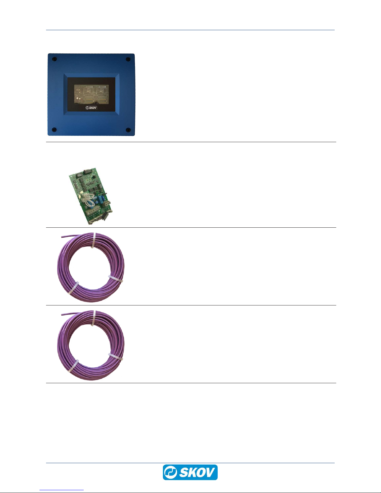
2 Product survey ...............................................................................................................................................6
2.1 Accessories.................................................................................................................................. 6
3 Mounting guide...............................................................................................................................................7
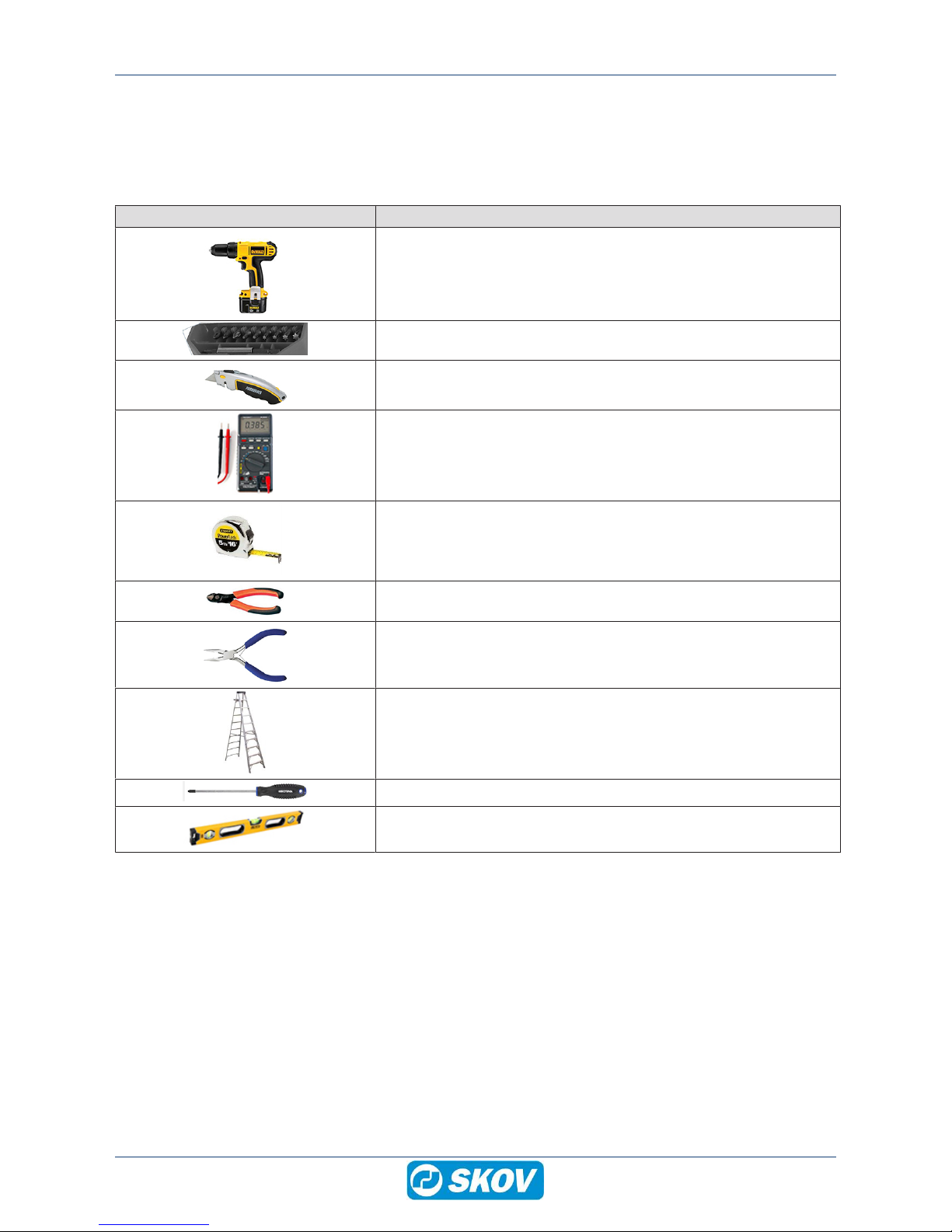
3.1 Recommended tools .................................................................................................................... 7
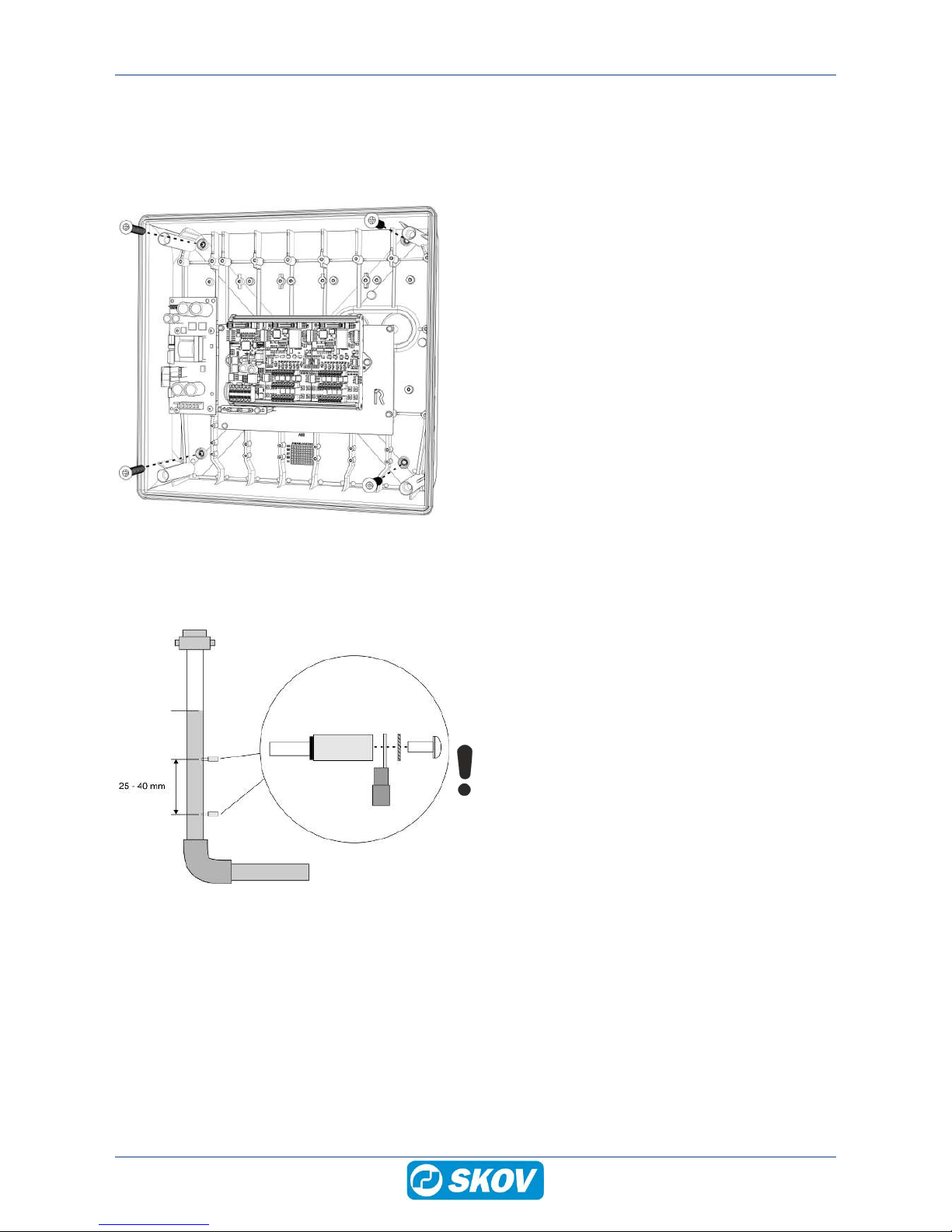
3.2 Assembly ..................................................................................................................................... 8
3.2.1 DOL 100 Water box ..................................................................................................................... 8
3.2.2 Water level sensor ....................................................................................................................... 8
4 Installation guide ............................................................................................................................................9
4.1 Electrical connection .................................................................................................................... 9
4.2 Cable routing................................................................................................................................ 9
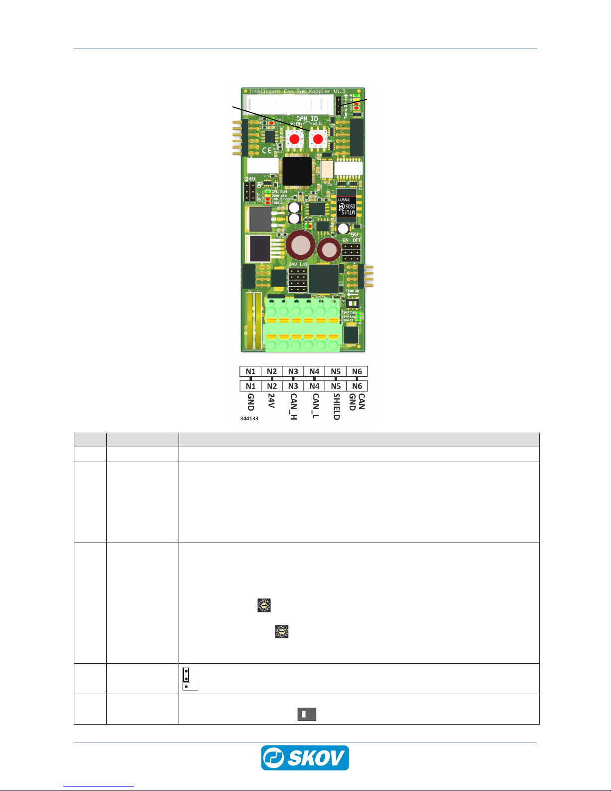
4.3 Nano CAN bus coupler .............................................................................................................. 10
4.3.1 LED indication on the CAN bus coupler..................................................................................... 11
4.4 Nano I/O module water 8l .......................................................................................................... 12
4.5 Connection in DOL 100.............................................................................................................. 13
4.6 Setting up the DOL 100 in the controller.................................................................................... 14
4.7 Cable plan.................................................................................................................................. 15
4.7.1 Water level sensor connected in series ..................................................................................... 15
4.8 Circuit diagram........................................................................................................................... 16
4.8.1 Water level sensor connected in series ..................................................................................... 16
5 Cleaning ........................................................................................................................................................17
6 Troubleshooting Guide ................................................................................................................................18
7 Technical data...............................................................................................................................................19

DOL 100 Water 8l/16l Box
Technical User Guide 5
1 Product description
The DOL 100 Water 8l/16l box is used for measuring the water level to ensure that the water pressure is in or-
der. The DOL 100 will promptly show faults in the water supply, e.g. clogged or broken water pipes or lacking
water supply.
DOL 100 transforms a signal from the water level sensor into digital signals and transmits them to the controller
using CAN bus communication.
• DA 100 Water is available in two variants:
• Connect up to 8 water level sensors to the DOL 100 Water 8I box.
• Connect up to 16 water level sensors to the DOL 100 Water 16I box.
(A)
(B)
(C)
(A) Controller
(B) Connect up to 16 water level sensors to
the DOL 100 Water 8I/16l box.
(C) Water level sensor

DOL 100 Water 8l/16l Box
6 Technical User Guide
2 Product survey
130181 DOL 100 Water 81 box
130182 DOL 100 Water 16l box
External I/O box for connection of water level sensors.
The DOL 100 converts the signal from the water level sensor into digital sig-
nals and transmits them to the controller using CAN bus communication.
Standard software / hardware of the DOL 530 series supports 13 I/O mod-
ules in total. DOL 100 is counted in as one module.
Water input terminals: 8 or 16
Is used with the data network module (132244) and a CAN bus cable
(130121-130128).
2.1 Accessories
132244 Data network module w. CAN bus
Always use the data network module when using external CAN bus com-
munication.
One for each controller.
130121 CAN bus cable 50 m
130125 CAN bus cable 100 m
130126 CAN bus cable 250 m
130122 CAN bus cable 500 m
For indoor use.
Use these cables in connection with external units using the CAN bus com-
munication.
130123 CAN bus cable UV 50 m
130127 CAN bus cable UV 100 m
130128 CAN bus cable UV 250 m
130124 CAN bus cable UV 500 m
For outdoor use.
Use these cables for external units that apply CAN bus communication and
for extending silo load cell cables.

DOL 100 Water 8l/16l Box
Technical User Guide 7
3 Mounting guide
3.1 Recommended tools
Below follows a list of tools recommended for installation of the DOL 100.
Item Description
Cordless drill
Screwdriver bits
Utility knife
Multimeter
Tape measure
Side cutter
Needle nose pliers
Ladder
Screwdriver
Spirit level

DOL 100 Water 8l/16l Box
8 Technical User Guide
3.2 Assembly
3.2.1 DOL 100 Water box
Mount DOL 100 Water box on the wall using four screws.
3.2.2 Water level sensor
Normal
water level
Drill two holes in the water pipe with a 2.4 mm drill when
the water level is normal.
The distance between the holes should be 20–40 mm.
Unscrew the two studs in the water pipe.
Make sure not to tear the thread.
Install the wire including cable clips on the stud with screw
and star washer; retain the pole when you tighten the
screw.

DOL 100 Water 8l/16l Box
Technical User Guide 9
4 Installation guide
4.1 Electrical connection
Installation, servicing and troubleshooting of all electrical equipment must be carried out by quali-
fied personnel in compliance with the applicable national and international standard EN 60204-1
and any other EU standards that are applicable in Europe.
The installation of a power supply isolator is required for each motor and power supply to facilitate
voltage-free work on the electrical equipment. SKOV does not supply the power supply isolator.
4.2 Cable routing
To prevent water from running into the DOL 100 via cables
and screwed connections, run the cables so that water does
not gather around the cable in the gasket of the screwed
connection.

DOL 100 Water 8l/16l Box
10 Technical User Guide
4.3 Nano CAN bus coupler
(A)
(A) (A)
(A)
(B)
(D)
(C)
(E)
Item Function Description
(A) Terminals Terminals to I/O modules
(B) N1 GND
N2 +24V
N3 CAN_H
N4 CAN_L
N5 SHIELD
N6 CAN GND
0 V
Power supply +24 VDC (max. 2.1 A)
CAN high (brown CAN bus)
CAN low (white CAN bus)
Shield (braided shield CAN bus)
(green CAN bus)
The terminal can also be used as a looped terminal strip to the next box.
(C) CAN ID CAN bus address (CAN ID). The address switches are used for setting the CAN ID.
The DOL 100 must have a specific CAN ID for the controller to communicate with it.
The address of the individual DOL 100 corresponds to the address in the controller in
the menu Technical | Setup | Installation | I/O Modules | Additional I/O Modules
Address switches X10 is set to 5 in connection with DOL 100 water and 3 in con-
nection with DOL 100 digital.
The address switches X01 are set to the displayed number or letter after the fig-
ure 5 or 3 in the controller.
If change of address, restart DOL 100 for the change to take effect.
(D) TERM ON
Jumper is set to (ON).
(E) TERM ON CAN bus termination. If DOL 100 is the last node in the CAN bus communication, the
jumper must be set to (ON) .

DOL 100 Water 8l/16l Box
Technical User Guide 11
4.3.1 LED indication on the CAN bus coupler
(A)
(B) (D)
(C)
(D)
Item Function LED col-
our
Description
(A)
24 V IN
Green
ON: 24 V DC power supply OK.
24 V Log ON: 24 V DC Internal OK.
24 V I/O ON: 24 V DC I/O fuse F1 OK.
(B)
Internal CAN bus RX Green ON: receiving data
Internal CAN bus TX Red ON: transmitting data
(C)
External CAN bus
RX
Green ON: receiving data
External CAN bus
TX
Red ON: transmitting data
(D)
CPU RUN Green FLASHES: OK.
OFF: not ready for operation
Operate Yellow States the CAN bus status
ON: operate
OFF: pre-operate
CAN ERROR Red OFF: CAN bus OK.
FLASHES: CAN bus error.
ERROR Red General error
Boot mode All LED ON (CPU RUN, Operate, CAN ER-
ROR and ERROR

DOL 100 Water 8l/16l Box
12 Technical User Guide
4.4 Nano I/O module water 8l
(A)
(A)
(B)
(B)
(E) (E)
(E)
(C)
(D) (D)
(C)
(F)
Nano I/O module # 1 Nano I/O module # 2
Item Function Description
(A) CAN ID
Jumper setting on I/O module # 1.
Jumper setting on I/O module # 2.
(B) TERM CAN bus termination.
The jumper is mounted on the I/O module furthest away from the CAN bus coupler.
(C) Terminals Water input terminal N11 -N28
Input terminals
(D) Terminals Water input terminal N11 -N28
GND
(E) DIP switch
DIP switch = WATER
(F) LED 1-8 Green = Water level OK

DOL 100 Water 8l/16l Box
Technical User Guide 13
4.5 Connection in DOL 100
24 V DC power supply
CAN bus connection, see dimensions below.
CAN_H = brown
CAN_L = white
CAN GND = green.
Strip the cable so the shield can be connected to the DOL
100 when mounting in the connection terminal.
As illustrated by the picture, the connection terminal can
also be used as a looped terminal strip to the next box.

DOL 100 Water 8l/16l Box
14 Technical User Guide
4.6 Setting up the DOL 100 in the controller
Make sure the CAN protocol is set to CANopen.
Technical | Setup | Installation | I/O Modules | CAN protocol
Select number of DOL 100.
The DOL 100 8I box supports up to 8 water level sensors.
The DOL 100 16I box supports up to 16 water level sensors.
The software supports up to 13 I/O modules and up to 64 water level
sensors. DOL 100 is counted in as one module.
Technical | Setup | Installation | I/O Modules | Extra I/O modules
Here you see the CAN bus address (CAN ID) and if it is connected.
Select number of water level sensors
Technical | Setup | Installation | Production | Water | Water level
The DOL 539/535 installation menu specifies which connection ter-
minal numbers and in which DOL 100 box the water level sensors must
be connected.
For correct connection of the water level sensors, see the menu Tech-
nical | Setup | Show connections
I/O#1 N11 = DOL 100 box no. 1, connection terminal N11.

DOL 100 Water 8l/16l Box
Technical User Guide 15
4.7 Cable plan
Power supply
Power supply
CAN bus cable max. 400 m (A)
(B)
(C)
(D)
(A) Power supply to the controller two-wire cable including earthing contact.
(B) Max. 400 m CAN bus communication cable between the DOL 100 Water 8l/16l box and the controller. The
CAN bus cable connecting all units of the system may not exceed 400 m.
(C) Max. 15 m 0.75 mm2 two-wire control cable between water level sensor and the DOL 100.
(D) Power supply to the DOL 100 Water 8I/16I box two-wire + earthing contact.
(E) Max. 15 m 0.75 mm2 one-wire control cable between water level sensor connected in series.
4.7.1 Water level sensor connected in series
Power supply
Power supply
CAN bus cable
max. 400 m
(A)
(B)
(E)
(D)
(E)
(E)

DOL 100 Water 8l/16l Box
16 Technical User Guide
4.8 Circuit diagram
4.8.1 Water level sensor connected in series

DOL 100 Water 8l/16l Box
Technical User Guide 17
5 Cleaning
The DOL 100 box is maintenance-free but should be kept free of litter and dirt.
Clean the product with a cloth that has been wrung out almost dry in water and avoid using:
• high-pressure cleaner
• solvents
• corrosive/caustic agents

DOL 100 Water 8l/16l Box
18 Technical User Guide
6 Troubleshooting Guide
Error
No light LED on the CAN bus
coupler.
Check the 24 V DC power supply to the DOL 100.
Check that you have installed the DOL 100 water 8I/16I box and water
level sensor in the controller, see section Setting up the DOL 100 in the
controller [}14]
No CAN bus communication con-
nectivity with the DOL 100 water
8l/16l box.
Check resistance between CAN H and CAN L; the resistance must be
approximately 60 ohms.
If the resistance is > 100 ohms, a termination is missing.
If the resistance is < 45 ohms, there are too many terminations.

DOL 100 Water 8l/16l Box
Technical User Guide 19
7 Technical data
Electrical
Operating voltage V AC 90 – 264
Max. power W 75
Max. power consumption A 0.7
CAN bus
Protocol CANopen in accordance with CiA301 and CiA401
Baud rate (fast) Kbd 125
Max. cable length m 400
Input terminals 8 Water
High KΩ < 10
Low KΩ > 25
Max. cable length m 15
Cross section mm20.75
Mechanical
Material ABS
Cable knock-out holes 20 x M25 for metrical cable glands
Environment
Temperature, operation °C 0 – 50
Protection class IP 54
It is assumed that the base surface is flat, i.e. difference of height is ≤
1.5 mm, and that the front panel screws are tightened to a minimum of
1.5 Nm.
Shipment
Dimensions (H x W x D) mm 381x400x170
Dimensions crated H x W x
D
mm 395x415x206
Weight g 3520
Shipping weight g 4560

604329 • 2018-08-07 • en • Made in Denmark
SKOV A/S • Hedelund 4 • Glyngøre • DK-7870 Roslev
Tel. +45 72 17 55 55 • www.skov.com • E-mail: [email protected]
This manual suits for next models
1
Table of contents