Microm TX3 Series User manual

Version 3.4 TX3 Touch Screen Installation Manual 1 (93)
LT-996 Copyright 2015
TX3 Series
Touch Screen
Installation Manual
All manuals and user guides at all-guides.com
all-guides.com

2 (93) TX3 Touch Screen Installation Manual Version 3.4
Copyright 2015 LT-996
All manuals and user guides at all-guides.com

Version 3.4 TX3 Touch Screen Installation Manual 3 (93)
LT-996 Copyright 2015
Contents
1 Introduction 7
1.1 TX3 Systems 8
1.2 Features 12
1.3 Touch Screen Sizes and Enclosures 12
1.4 Touch Screen Accessories 13
1.5 Warranty and Special Notices 14
1.6 About This Manual 14
1.7 Contact Us 15
2 Enclosure Installation 17
2.1 Installing the Enclosures and Touch Screen 18
2.2 Installing the 15” Kiosk 19
2.3 Installing the 15” Touch Screen Surface Mount Enclosure 25
2.4 Installing the 15” Touch Screen Flush Mount Enclosure 28
2.5 Installing the 22” Touch Screens 32
2.6 Assembling the TX3-T-KIOSK Stand 38
2.7 Installing the Power Supply Enclosure 46
3 Touch Screen System and Setup 51
3.1 Touch Screen System 52
3.2 Touch Screen Panels 55
3.3 Controller Boards 58
3.4 Grounding the 15” Touch Screen 61
3.5 Grounding the 22” Touch Screen 61
3.6 Connecting to the External Power Supply 62
3.7 Installing the Postal Lock 64
3.8 Installing the Telephone Lines 64
3.9 Installing Optional Components 64
3.10 Verifying Installed Components 66
3.11 Beginning Configuration 67
3.12 Shutting Down the Touch Screen 68
3.13 Installing a Logitech c615 HD Webcam on the 22” Touch Screen 69
3.14 Replacing the 3M™ Multi-Touch Display C2167PW on the 22” Touch
Screen 70
3.15 Installing the TX3-P300-HA Card Reader in the 22” Touch Screen 74
3.16 Installing a RB-MD-1093 Two Door Controller Network Board 76
4 Adding Controllers 77
4.1 Adding a Controller 78
5 Appendix 79
5.1 Specifications 80
6 Resident Operating Instructions 83
6.1 NSL Resident Operating Instructions 84
6.2 ADC Resident Operating Instructions 86
Warranty & Warning Information 87
Special Notices 90
All manuals and user guides at all-guides.com

4 (93) TX3 Touch Screen Installation Manual Version 3.4
Copyright 2015 LT-996
All manuals and user guides at all-guides.com

Version 3.4 TX3 Touch Screen Installation Manual 5 (93)
LT-996 Copyright 2015
List of Figures
Figure 1 TX3 devices on an RS-485 network. 9
Figure 2 TX3 devices connected to an ethernet TCP/IP network. Devices connected to
an ethernet network are Master Nodes. 10
Figure 3 TX3 devices connected to a combination ethernet TCP/IP network with RS-485
subnetworks. 11
Figure 4 Kiosk Dimensions (inches) 19
Figure 5 Reinforcement Bracket with bolts 20
Figure 6 Reinforcement Bracket with nuts 21
Figure 7 Kiosk Base Plate with bolts 21
Figure 8 Kiosk Mounting Holes 21
Figure 9 Base Plate Mounting Holes 22
Figure 10 Base Plate Dimensions (inches) 22
Figure 11 Fitting the Kiosk on the Base Plate 23
Figure 12 Fitting the Kiosk on the Base Plate (from below) 23
Figure 13 Attach the Kiosk to the base plate 24
Figure 14 15” Touch Screen Surface Mount Back Dimensions (inches) 25
Figure 15 15” Touch Screen Surface Mount Front Dimensions (inches) 26
Figure 16 Touch Screen Surface Mount 27
Figure 17 15” Touch Screen Flush Mount Back Dimensions (inches) 28
Figure 18 15” Touch Screen Flush Mount Front Dimensions (inches) 29
Figure 19 Flush Mount Enclosure 30
Figure 20 Surface mounting the enclosure 33
Figure 21 Flush mounting the enclosure 34
Figure 22 22” Touch Screen Flush Mount Dimensions (inches) 36
Figure 23 22” Touch Screen Surface Mount Dimensions (inches) 37
Figure 24 22” Touch Screen Dimensions (inches) 38
Figure 25 15” Touch Screen Dimensions (inches) 39
Figure 26 Components of TX3-T-KIOSK 40
Figure 27 Base Plate Mounting Holes 41
Figure 28 Base Plate Dimensions (inches) 41
Figure 29 Fit the stand on the Base Plate 42
Figure 30 Fit the stand on the Base Plate (from below) 42
Figure 31 Attach the stand to the base plate 43
All manuals and user guides at all-guides.com

6 (93) TX3 Touch Screen Installation Manual Version 3.4
Copyright 2015 LT-996
Figure 32 Attach the 22” Touch Screen to the stand 44
Figure 33 Attach the 22” Touch Screen to the stand 45
Figure 34 Inside the Switching Power Supply Box 46
Figure 35 Power Supply Voltage Selection Switch 47
Figure 36 Touch Screen Power Supply Enclosure 48
Figure 37 Single Touch Screen 53
Figure 38 Single Touch Screen with ADC and NSL Lines 54
Figure 39 15” Touch Screen Panel Components 55
Figure 40 22” Touch Screen Inside Door 57
Figure 41 Controller Board Panel for 15” Touch Screens 58
Figure 42 Controller Board Panel for 22” Touch Screens 59
Figure 43 Controller Board Connectors - Top 60
Figure 44 Controller Board Connectors - Bottom 61
Figure 45 Grounding the 22” Touch Screen 62
Figure 46 MD-990 Terminal Block Wiring 63
Figure 47 Connecting additional RS-485 Terminal Connector to the First or Last Node of
Network 66
Figure 48 Position of the camera on the 22” Touch Screen door 69
Figure 49 Inside of door showing position of the four #6-32 nuts 71
Figure 50 The two brackets (CH-1165) holding the display 72
Figure 51 Power button 73
Figure 52 Position of the TX3-P300-HA Card Reader 74
Figure 53 The TX3-P300-HA Card Reader 75
Figure 54 TX3-P300-HA and Bracket 75
All manuals and user guides at all-guides.com
all-guides.com

Introduction
Version 3.4 TX3 Touch Screen Installation Manual 7 (93)
LT-996 Copyright 2015
1
Introduction
This manual provides information about the installation and operation of the
Touch Screen, and must be read in its entirety before beginning any installation
work.
Installation must be performed by a qualified technician and must adhere to the
standards and special notices set by the local regulatory bodies.
Note: Mircom periodically updates panel firmware and Configurator
Software to add features and correct any minor inconsistencies.
For information about the latest firmware or software visit the
Mircom website at www.mircom.com.
For warranty and special notices information see the Warranty and Special
Notices chapter on page 87.
Warning: The Touch Screen assembly must be grounded by a qualified
electrician. An improperly grounded unit can result in
equipment malfunction and electrical shock.
This manual explains
• Touch Screen System
• Installation and Setup
• TX3 Integration
• Resident Operating Instructions
All manuals and user guides at all-guides.com

8 (93) TX3 Touch Screen Installation Manual Version 3.4
Copyright 2015 LT-996
Introduction
1.1 TX3 Systems
The Mircom's TX3 series of Touch Screens provide high quality two-way
communication between residents and their visitors in a multi-unit dwelling
establishment.
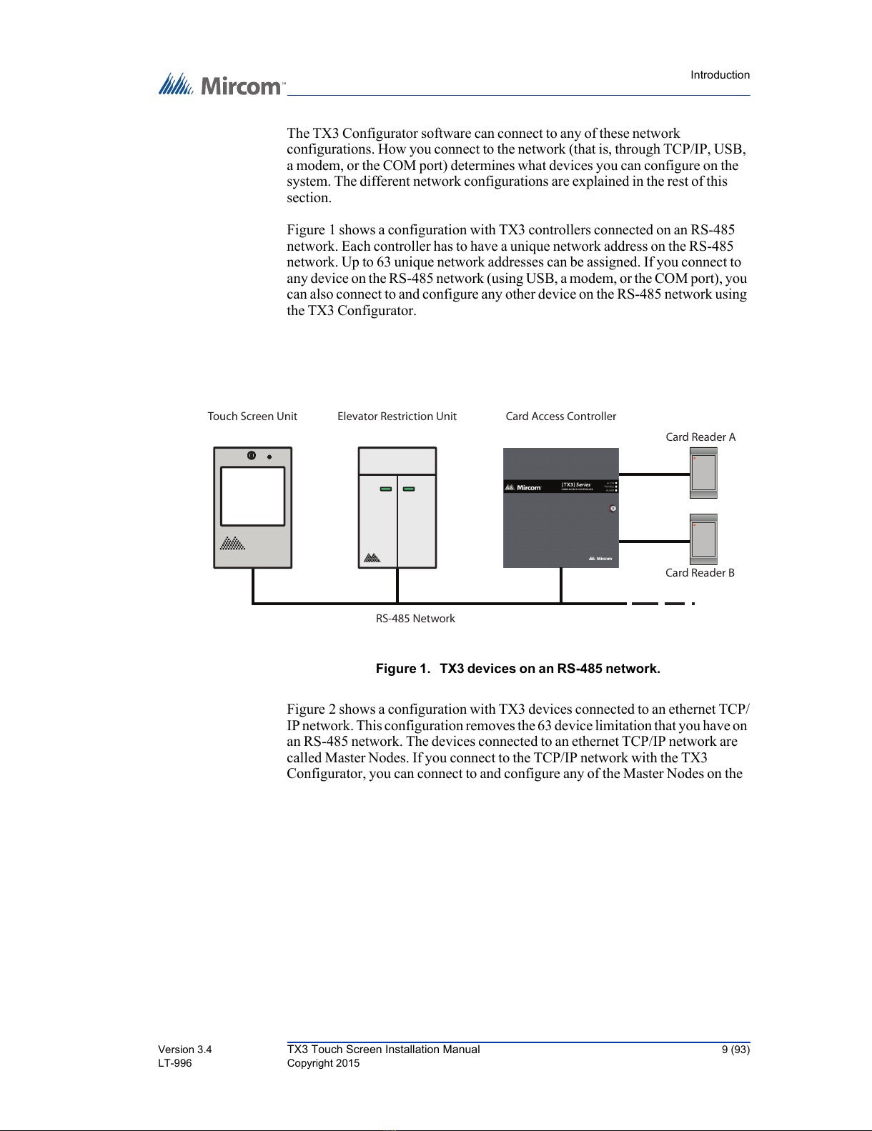
The basic TX3 system consists of the TX3 Touch Screen and depending on the
application, may be integrated with a combination of Mircom Telephone Access,
Card Access, and Elevator Restriction Units. All access systems may be
networked together using a peer-to-peer RS-485 network, an ethernet TCP/IP
network, or a combination of a TCP/IP network with RS-485 subnetworks.
A maximum of 63 units are supported on an RS-485 network or subnetwork.
Valid network addresses range from 1 to 63. Units with a real time clock, such as
Touch Screens and Card Access Units, require the address node to be 1. If you are
using an ethernet TCP/IP network or a combination of a TCP/IP network with
RS-485 subnetworks you can add much more than 63 devices to your system. For
more information, see section 1.1.3, Other Controllers in this chapter.
The TX3 system is capable of providing ADC or NSL type telephone access
control from a single panel or from a networked system.
The access system can be configured as an autodialer controller (ADC) or as a no
subscriber line (NSL) system. Both system setups can be configured for multiple
entrances with independent doors and control devices such as electric door locks,
cameras, and garage doors.
1.1.1 ADC and NSL Capability
TX3 supports full ADC and NSL telephone connectivity from a single Touch
Screen panel or from a networked system. A single panel supports up to five
ADC and/or NSL telephone lines.
1.1.2 Elevator Restriction Units
The TX3-ER-8 Elevator Restriction Unit limits building accessibility by
granting visitor access only to the destination floor.
1.1.3 Other Controllers
Mircom devices, such as the Touch Screen and the Lobby Control Unit, can be
networked with the TX3 system through a peer-to-peer RS-485 network, an
ethernet TCP/IP network, or a combination of an ethernet network with RS-485
subnetworks.
All manuals and user guides at all-guides.com

Introduction
Version 3.4 TX3 Touch Screen Installation Manual 9 (93)
LT-996 Copyright 2015
The TX3 Configurator software can connect to any of these network
configurations. How you connect to the network (that is, through TCP/IP, USB,
a modem, or the COM port) determines what devices you can configure on the
system. The different network configurations are explained in the rest of this
section.
Figure 1 shows a configuration with TX3 controllers connected on an RS-485
network. Each controller has to have a unique network address on the RS-485
network. Up to 63 unique network addresses can be assigned. If you connect to
any device on the RS-485 network (using USB, a modem, or the COM port), you
can also connect to and configure any other device on the RS-485 network using
the TX3 Configurator.
Figure 1. TX3 devices on an RS-485 network.
Figure 2 shows a configuration with TX3 devices connected to an ethernet TCP/
IP network. This configuration removes the 63 device limitation that you have on
an RS-485 network. The devices connected to an ethernet TCP/IP network are
called Master Nodes. If you connect to the TCP/IP network with the TX3
Configurator, you can connect to and configure any of the Master Nodes on the
RS-485 Network
Card Reader B
Card Reader A
Card Access Controller
T
ouch Screen Unit Elevator Restriction Unit
All manuals and user guides at all-guides.com

10 (93) TX3 Touch Screen Installation Manual Version 3.4
Copyright 2015 LT-996
Introduction
ethernet TCP/IP network. If you connect directly to one of the Master Nodes
using USB, a modem, or a COM port, you will be able to configure that device but
not any other device.
Figure 2. TX3 devices connected to an ethernet TCP/IP network. Devices
connected to an ethernet network are Master Nodes.
Notes: In order for a panel to be a Master Node it must satisfy the following
conditions.
•It must be IP capable. Panels that are IP capable are usually
denoted by a “-A” at the end of their model names.
•If the panel is not a Touch Screen, it must have a TX3-IP IP
Module installed.
Card Reader B
Card Reader A
Card Access Controller
(Master Node)
Ethernet Network
Elevator Restriction Unit
(Master Node)
Touch Screen Unit
(Master Node)
All manuals and user guides at all-guides.com

Introduction
Version 3.4 TX3 Touch Screen Installation Manual 11 (93)
LT-996 Copyright 2015
Figure 3 shows a configuration with TX3 devices connected on both an ethernet
TCP/IP network and on RS-485 subnetworks. Devices connected to a Master
Node’s RS-485 subnetwork are Slave Nodes to the Master Node. Each RS-485
subnetwork can have up to 63 devices connected to it; you can still have more
than 63 Master Nodes connected to the ethernet network.
Figure 3. TX3 devices connected to a combination ethernet TCP/IP
network with RS-485 subnetworks.
If you connect to the ethernet TCP/IP network with the TX3 Configurator, you
can configure any of the nodes in this configuration. If you connect directly to a
device using USB, a modem, or a COM port, you will only be able to configure
devices that are on the same RS-485 subnetwork as that device.
Note: Normally, there can only be one Master Node on an RS-485
subnetwork. That is, you cannot connect one RS-485 subnetwork to
another RS-485 subnetwork. However, if you want to connect to a
Touch Screen panel remotely over the Internet (for instance, to
RS-485 Subnetwork
Touch Screen
(Slave Node)
Card Reader B
Card Reader A
Card Access Controller
(Slave Node)
Card Reader B
Card Reader A
Card Access Controller
(Slave Node)
RS-485 Subnetwork
Ethernet Network
Lobby Control Unit
(Master Node)
2
ABC
3
DEF
1
5
JKL
6
MNO
4
GHI
8
TUV
9
WXYZ
7
PQRS
0
*#
Lobby Control Unit
(Master Node)
2
ABC
3
DEF
1
5
JKL
6
MNO
4
GHI
8
TUV
9
WXYZ
7
PQRS
0
*#
Elevator Restriction Unit
(Slave Node)
All manuals and user guides at all-guides.com
all-guides.com

12 (93) TX3 Touch Screen Installation Manual Version 3.4
Copyright 2015 LT-996
Introduction
configure Touch Screen options such as color and themes), the
Touch Screen panel must be set as an Master Node even if there is
no slave panel connected to it.
1.2 Features
Features of the TX3 series include:
• Stainless steel front panel
• Large touch screen display that eliminates the need for an external
directory
• Provisions for postal lock and camera
• Multilingual Display and Voice Greeting (English, French-Canadian and
Spanish) that provides instructions on how to use the Touch Screen
• Concierge/Security Desk/Guard Phone capability
• Card Access Interface
• Supports both Auto Dialer (ADC) and NSL (no phone bill)
• Ability to network panels together (peer-to-peer)
• Hands free, full duplex communication
• Flexible one to four digit resident dial codes
• Dials up to 18-digit telephone numbers
• System can be configured locally using the touchscreen or a computer with
the TX3 configuration software
• Upload/download configuration files without taking the whole system off-
line
• Programming from one location
• Records a maximum of 5000 event logs
• Elevator restriction capability
• Schedule-based call restrictions provide more security and flexibility
• Capability of one person testing the NSL controller without using the
Touch Screen
• Industry Canada and F.C.C. approved
1.3 Touch Screen Sizes and Enclosures
There are three types of enclosures for the 15 inch Touch Screen: kiosk, surface
mount, and flush mount.
All manuals and user guides at all-guides.com

Introduction
Version 3.4 TX3 Touch Screen Installation Manual 13 (93)
LT-996 Copyright 2015
1.3.1 15 Inch Models
The 15 inch Touch Screen models are stand alone, surface or flush mounted.
TX3-TOUCH-K15-A. 15” Touch Screen kiosk, stainless steel finish Touch
Screen with speaker, microswitch for postal lock and a PS-4P transformer plug.
Designed for indoor use. The TX3-TOUCH-K15-A can be configured as a
Master Node on an ethernet network.
TX3-TOUCH-F15-A. 15” Touch Screen flush mount, stainless steel finish
Touch Screen with speaker, microswitch for postal lock, flush mounting back
box and a PS-4P transformer plug. Designed for indoor use. Can be configured as
a Master Node on an ethernet network.
TX3-TOUCH-S15-A. 15” Touch Screen surface mount, stainless steel finish
Touch Screen with speaker, microswitch for postal lock, flush mounting back
box and a PS-4P transformer plug. Designed for indoor use. Can be configured as
a Master Node on an ethernet network.
1.3.2 22 Inch Models
The 22 inch Touch Screen models are surface or flush mounted.
TX3-TOUCH-S22. 22” Touch Screen surface mount, stainless steel finish
Touch Screen with speaker, microswitch for postal lock, surface mounting back
box and a PS-4P transformer plug. Designed for indoor use. The TX3-TOUCH-
S22 can be configured as a Master Node on an ethernet network.
TX3-TOUCH-F22. 22” Touch Screen flush mount, stainless steel finish Touch
Screen with speaker, microswitch for postal lock, flush mounting back box and a
PS-4P transformer plug. Designed for indoor use. The TX3-TOUCH-F22 can be
configured as a Master Node on an ethernet network.
1.4 Touch Screen Accessories
The Touch Screen accessories consist of the following items:
• TX3-T-KIOSK: Black free standing mount for TOUCH Series
•CAM-2TX3Camera
• TX3-GPM Guard Phone Module
•PostalLock
• TX3-USB-AD Kit
All manuals and user guides at all-guides.com

14 (93) TX3 Touch Screen Installation Manual Version 3.4
Copyright 2015 LT-996
Introduction
1.5 Warranty and Special Notices
Mircom values your business and always attempts to provide you with the very
best service.
Please see the Warranty and Special Notices chapter on page 87 for information
about the warranty and special notices about equipment use.
1.6 About This Manual
This manual provides comprehensive information on the installation and
configuration of the TX3 Series Touch Screen by the installation technician.
Tasks are described in the order that they are likely to be performed.
This manual applies to the following models:
• TX3-TOUCH-K15-A
• TX3-TOUCH-F15-A
• TX3-TOUCH-S15-A
•TX3-TOUCH-S22
•TX3-TOUCH-F22
• TX3-T-KIOSK
1.6.1 Version Control
The version number appears on the front cover and changes whenever there is a
major or minor update to any part of the system regarding operation or
configuration.
The following convention indicates major or minor changes:
Initial release. Version 1.00.0
Major change. Version 2.00.0
Minor change. Version 2.01.0
Pre-release changes. Version 2.01.1
1.6.2 Additional Documentation
For additional documentation, see the following Mircom literature:
• TX3 Configuration and Administrator Manual LT-995
All manuals and user guides at all-guides.com

Introduction
Version 3.4 TX3 Touch Screen Installation Manual 15 (93)
LT-996 Copyright 2015
• TX3-Telephone Access System Installation and Operation Manual LT-
969
• TX3-CX Card Access System Installation and Operation Manual LT-980
• TX3-CX-A8 Aperio Interface Panel Installation and Operation Manual
LT-1160
• TX3 Two Door Card Access System Kit Catalogue Number 6531
• TX3 Series Elevator Restriction Accessories Catalogue Number 6532
1.7 Contact Us
Mircom fosters a collaborative support process and environment in providing
early feedback to meet your specific needs.
You can contact us from Monday to Friday 8:00 A.M. to 5:00 P.M. E.S.T.
1.7.1 General Inquiries
For general inquiries call us at the following numbers:
Toll Free: 1-888-660-4655
Local: 905-660-4655
1.7.2 Customer Service
Customer service is available at the following numbers:
Toll Free: 1-888-MIRCOM5
Local: 905-695-3535
Local Fax: 905-660-4113
Toll-Free Fax: 1-888-660-4113
All manuals and user guides at all-guides.com

16 (93) TX3 Touch Screen Installation Manual Version 3.4
Copyright 2015 LT-996
Introduction
1.7.3 Website
Visit the Mircom website, at www.mircom.com, to find the product information
you are looking for and to learn about troubleshooting, training and technical
support options.
The website provides avenues for customers to ask questions about new and
existing technologies, and receive expert technical support about software and
products. Visit www.mircom.com/chat.
1.7.4 Email
As a customer you quickly become informed on how we can help with new
1.7.5 Technical Support
For technical support contact Mircom’s Technical Support Department between
8 A.M. and 5 P.M. (EST) Monday through Friday, excluding holidays.
Toll Free: 1-888-MIRCOM5
Local: 905-695-3535
Local Phone: 905-660-4655
Toll Free Phone: 1-888-660-4655
Email: techsupport@mircom.com
All manuals and user guides at all-guides.com
all-guides.com

Enclosure Installation
Version 3.4 TX3 Touch Screen Installation Manual 17 (93)
LT-996 Copyright 2015
2
Enclosure Installation
This chapter provides information on how to install the various enclosures and
pre-assembled components.
This chapter explains
• Installing the 15” Kiosk - page 19
• Installing the 15” Touch Screen Surface Mount Enclosure - page 25
• Installing the 15” Touch Screen Flush Mount Enclosure - page 28
• Installing the 22” Touch Screens - page 32
• Assembling the TX3-T-KIOSK Stand - page 38
• Installing the Power Supply Enclosure - page 46
All manuals and user guides at all-guides.com

18 (93) TX3 Touch Screen Installation Manual Version 3.4
Copyright 2015 LT-996
Enclosure Installation
2.1 Installing the Enclosures and Touch Screen
The Touch Screen Kiosk, Surface Mount and Flush Mounts units consist of the
following pre-assembled components:
Kiosk. The kiosk is a pedestal mounted Touch Screen TX3-TOUCH-K15-A unit
and consists of the following components:
• Touch Screen Base Plate
• Touch Screen Kiosk
• Touch Screen Panel
• Touch Screen Speakers
• Touch Screen Frame
• Touch Screen Door
Surface Mount. The surface mount unit is a TX3-TOUCH-S15-A or TX3-
TOUCH-S22 unit and consists of the following components:
• Touch Screen Enclosure
• Touch Screen Panel
• Touch Screen Speakers
• Touch Screen Frame
• Touch Screen Door
Flush Mount. The surface mount unit is a TX3-TOUCH-F15-A or TX3-
TOUCH-F22 unit and consists of the following components:
• Touch Screen Enclosure
• Touch Screen Panel
• Touch Screen Speakers
• Touch Screen Frame
• Touch Screen Door
All manuals and user guides at all-guides.com

Enclosure Installation
Version 3.4 TX3 Touch Screen Installation Manual 19 (93)
LT-996 Copyright 2015
2.2 Installing the 15” Kiosk
Figure 4. Kiosk Dimensions (inches)
The Kiosk mounts to the floor inside the building near the entrance, close to the
power source and telephone infrastructure. Access for the power and
communication cables is provided through a cutout in the base plate.
To install the Kiosk you must:
• Remove the reinforcement bracket and the base plate.
• Attach the base plate to the floor, and run the wiring through the base plate
opening.
• Attach the Kiosk to the base plate.
• Attach the reinforcement bracket to the Kiosk.
Follow the instructions below to complete these steps.
You will need:
4 bolts to attach the base plate to the floor. The holes in the base plate are 0.406”
in diameter.
17.950
50.0
14.187
All manuals and user guides at all-guides.com

20 (93) TX3 Touch Screen Installation Manual Version 3.4
Copyright 2015 LT-996
Enclosure Installation
To install the Touch Screen Kiosk base plate
1. Find a suitable location for the Kiosk next to the building entrance and
above the building electrical and communications conduit.
2. Remove the door from the Kiosk.
3. Remove the 4 bolts from the reinforcement bracket, as shown in Figure 5.
Figure 5. Reinforcement Bracket with bolts
4. Remove the 6 nuts on the reinforcement bracket, as show in Figure 6, and
then remove the bracket.
All manuals and user guides at all-guides.com
Other manuals for TX3 Series
1
This manual suits for next models
3
Table of contents