Micromark MM23207 Manual

INSTALLATION & OPERATING INSTRUCTIONS
IIMMPPOORRTTAANNTT::PPLLEEAASSEERREEAADDTTHHEESSEEIINNSSTTRRUUCCTTIIOONNSSCCAARREEFFUULLLLYYBBEEFFOORREEAATTTTEEMMPPTTIINNGGTTOOIINNSSTTAALLLLTTHHIISSAALLAARRMMSSYYSSTTEEMM..
IIFFTTHHEESSYYSSTTEEMMIISSBBEEIINNGGIINNSSTTAALLLLEEDDBBYYAASSEECCUURRIITTYYIINNSSTTAALLLLEERROORREELLEECCTTRRIICCAALLEENNGGIINNEEEERR,,PPLLEEAASSEEEENNSSUURREETTHHAATTAA
CCOOPPYYOOFFTTHHEESSEEIINNSSTTRRUUCCTTIIOONNSSIISSGGIIVVEENNTTOOTTHHEECCUUSSTTOOMMEERRFFOORRRREETTEENNTTIIOONNAANNDDFFUUTTUURREERREEFFEERREENNCCEE..
This alarm system can provide valuable protection for your home and property if used properly. However, the system cannot
guarantee complete protection against burglary or robbery. Therefore, the manufacturer, distributor or supplier will not be
held responsible for any loss or damage which may occur.
6-ZONE EASYFIT INTRUDER ALARM
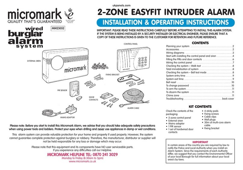
Check the contents of the
packaging:
• 1x6 zone control panel
• External siren
• 9V PP3 alkaline back up
system battery
• Mains adaptor
• 4 PIR sensors
• 2 sets of hardwired door
contacts
• 8 sticky pads
• Fixing screws
• Cable clips
• Wall plugs
• Screwdriver (fits PIR cover
screws)
• 50m of multi-core alarm
cable
• Fixing bracket
IMPORTANT
In certain areas of the country you are required by law to
notify the Police and Local Authority when you install an
Alarm System. Since the requirements of each Authority
differ, we suggest that you contact the Environmental Officer
of your local Borough for full information about your local
area‘s by-laws.
Please note that this equipment and its components have NO user serviceable parts.
If you experience any difficulties call our Helpline.
MMIICCRROOMMAARRKKHHEELLPPLLIINNEETTEELL::0088770022441133002299
Monday to Friday (8.30am to 5pm)
www.micromark.co.uk
CCOONNTTEENNTTSS
Planning your system . . . . . . . . . . . . . . . . . . . . . . . . . . . . . . . . .2
Wiring diagrams . . . . . . . . . . . . . . . . . . . . . . . . . . . . . . . . . . . . .3
Start with installing the control panel and siren . . . . . . . . . . . .4
Fitting PIRs and door contacts . . . . . . . . . . . . . . . . . . . . . . . . . .6
Wiring the control panel . . . . . . . . . . . . . . . . . . . . . . . . . . . . . . .7
Control panel status . . . . . . . . . . . . . . . . . . . . . . . . . . . . . . . . . .8
Total immobilisation of system . . . . . . . . . . . . . . . . . . . . . . . . . .8
Checking the system – Walk test . . . . . . . . . . . . . . . . . . . . . . . .8
Checking the system – Bell test mode . . . . . . . . . . . . . . . . . . . .8
System entry time . . . . . . . . . . . . . . . . . . . . . . . . . . . . . . . . . . . .9
System exit time . . . . . . . . . . . . . . . . . . . . . . . . . . . . . . . . . . . . .9
Bell reset . . . . . . . . . . . . . . . . . . . . . . . . . . . . . . . . . . . . . . . . . .10
To change password . . . . . . . . . . . . . . . . . . . . . . . . . . . . . . . .10
To arm the system . . . . . . . . . . . . . . . . . . . . . . . . . . . . . . . . . . .11
To disarm the system . . . . . . . . . . . . . . . . . . . . . . . . . . . . . . . . .11
Panic alarm . . . . . . . . . . . . . . . . . . . . . . . . . . . . . . . . . . . . . . . .11
Chime zone . . . . . . . . . . . . . . . . . . . . . . . . . . . . . . . . . . . . . . . .11
Part Guard . . . . . . . . . . . . . . . . . . . . . . . . . . . . . . . . .Back cover
Troubleshooting . . . . . . . . . . . . . . . . . . . . . . . . . . . . .Back cover
KKIITTCCOONNTTEENNTTSS
PPlleeaasseennoottee::BBeeffoorreeyyoouussttaarrttttooiinnssttaalllltthhiissMMiiccrroommaarrkkAAllaarrmm,,wweeaaddvviisseetthhaattyyoouusshhoouullddttaakkeeaaddeeqquuaatteessaaffeettyypprreeccaauuttiioonnss
wwhheennuussiinnggppoowweerrttoooollssaannddllaaddddeerrss..PPrrootteeccttyyoouurreeyyeesswwhheennddrriilllliinnggaanndd
nneevveerr
uusseeaapppplliiaanncceessiinnddaammppoorrwweettccoonnddiittiioonnss..
PIR SENSORS
MAINS ADAPTOR
DOOR
CONTACTS
ALARM CABLE
FIXING BRACKET
CONTROL PANEL
SIREN
www.ukpanels.com

WWHHAATTIISSAAZZOONNEE??
Throughout these instructions the term ZONE is used, meaning a defined area of protection. A zone can be one room, or any number of rooms, connected to the same
connection on the control panel. With this system there are 4 areas you can guard, and with the Panic alarm and 24-hour anti-tamper guard, the system gives 6-zone
protection.
The anti-tamper guard, protects against cutting through the cable to the outside siren box or removal of internal control panel. The alarm will activate instantly if any tampering
of the system occurs.
ZZoonnee11is a time delay zone to allow you time after you have armed the system to exit or enter the property before the siren activates.
ZZoonnee22is an intermediate zone. On arming the system it allows you to pass through for the exit and entry times, providing the sensor on zone 1 has been tripped. At all other
times the zone is instant.
ZZoonnee33can be armed as Full Guard (Instant) or Part Guard (non-armed).
ZZoonnee44is an instant zone.
ZZoonnee5524-hour anti-tamper guard. Protects the system 24 hours a day.
ZZoonnee66Panic Alarm. Sets off the internal and external alarms on pressing the two keypad buttons (P E) at the same time.
IIMMPPOORRTTAANNTTPPOOIINNTTSSTTOO
CCOONNSSIIDDEERR
When planning your system and before installation
consider the following points:
• The PIR units detect body movement of persons or
animals in the detection zone*. Door contacts are
used to detect if a door or window has been
opened.
See the diagram to help you plan your system.
*• OOnnllyyoonneePPIIRRccaannbbeeiinnssttaalllleeddiinnaannyyoonneezzoonnee..
• Zone 1 is the Entry/Exit zone.
• Never place a PIR in zone 3 or 4 where the control
panel is in view of the PIR, otherwise it will be
impossible to arm the system.
• Use zone 3 for Part Guard (refer to page 11).
• Do not position PIRs facing windows, in direct
sunlight, above a heat source such as radiator, or in
conservatories or draughty areas.
• When this system is armed, keep pets out of
areas protected by PIR sensors.
• Position control panel near a power socket.
Now start by planning layout for your home.
2
PLANNING YOUR SYSTEM ACCESSORIES
MMMM99445522
SSuurrffaacceemmaaggnneettiiccddoooorr
ccoonnttaaccttss..
2 terminal single reed.
White high impact
plastic. 4 fixing screws
and 2 adhesive pads
included.
SSiirreennccoovveerrss
MMMM99445555
’C’ type. White
polypropylene
MMMM99446611
’C’ type. Yellow
polypropylene
MMMM99445533--44ccoorreeaallaarrmmccaabbllee
30m low voltage alarm cable. NNoottffoorr
uusseewwiitthhmmaaiinnssvvoollttaaggee..White sheath,
4 core (red/black/blue/yellow). NNoottee::
ddiissrreeggaarrddtthheebblluueewwiirreeoonntthhiisskkiitt..
MMMM99445544--3300ccaabbllee
cclliippss
35mm flat. White
These accessories are available direct
from your retailer, or from the customer
helpline 0870 241 3029.
ZZOONNEE44––Instant zone
Door contacts can be added to any zone and
are available as an accessory.
ZZOONNEE11– Use this as your
entry/exit timed zone. PIR or door
contacts.
WWEEAATTHHEERRPPRROOOOFF
SSIIRREENN
We suggest that outside
doors are protected by a
door contact, as 71% of
reported burglary entries
are made through a front
or back door.
Home Office statistics,
Jan. 2001
ZZOONNEE44--
Instant
zone.
PIR or door
contacts.
ZZOONNEE33
Use this as an instant
or part guard zone.
Door contacts can be
added as an accessory.
CCOONNTTRROOLL
PPAANNEELL
ZZOONNEE22--
Intermediate
zone
NNoottee::This alarm must only be used when
powered by the mains adaptor, the internal battery
operates as a stabilizing back up supply in the
event of short periods of power loss, and will not
run the system over a long period.
In the event of an activation during a power loss
period all of the zone LEDs will illuminate when you
disarm the system. You will have to reset the
system using your personal security code.
www.ukpanels.com

3
+ - 1 2 3 4
ZONES
CONTROL
PANEL
ANTI-TAMPER
SWITCH
TERMINAL
BLOCK
SNAP CONNECTOR
TO MAINS POWER
ADAPTOR
SIREN/BELL BOX
JACK
PLUG
BATTERY
COMPARTMENT
3-WAY TERMINAL
BLOCK
PIR
PIR
PIR
PIR
DOOR CONTACT DOOR CONTACT
ZONE 1
Use this as your entry/exit.
The door contacts share the
cable run with the PIR.
ZONE 2
The door contacts share the
cable run with the PIR.
ZONE 3
This is used for the Part
Guard Zone. Door contacts
can also be fitted and are
available as optional extras.
ZONE 4
Door contacts can also be
fitted and are available as
optional extras.
WIRING DIAGRAM SHOWING PIR AND DOOR CONTACTS
WIRED SEPARATELY TO CONTROL PANEL IN THE SAME ZONE
WIRING DIAGRAM SHOWING ADDING AN EXTRA CONTACT
TO AN EXISTING DOOR CONTACT
TYPICAL WIRING DIAGRAM SHOWING PIR AND DOOR CONTACTS
WITHIN ZONE 1 THE ENTRY/EXIT ZONE
BLACK WIRES TWISTED AND
TAPED TOGETHER
TRIM RED WIRES BACK TO INSULATION
AND COVER WITH TAPE
TRIM AND TAPE RED
WIRE BACK TO
INSULATION AND
COVER WITH TAPE
IIffyyoouuddoonnoottuusseeaa
zzoonnee,,yyoouummuussttlleeaavveeaa
lliinnkkiinnggwwiirreeccoonnnneeccttiioonn
ffrroommtthheezzoonnee
ccoonnnneeccttiioonnssttootthhee
nneeggaattiivvee((bbllaacckk))
tteerrmmiinnaall..
TRIM AND TAPE RED
WIRE BACK TO
INSULATION
BLACK &
YELLOW
WIRES
TWISTED
& TAPED
FROM PANEL ZONE CONNECTOR
AA
B
When wiring PIR and door contacts to same zone, wiring can be as diagrams or
AB***
**
**
**
Note: Only 1 PIR can be fitted to a zone. You can fit up to 6 door contacts per zone
WIRING DIAGRAMS
www.ukpanels.com

4
START WITH INSTALLING THE CONTROL PANEL AND SIREN
Position the control panel near a mains socket and
within easy reach of the entry/exit door.
Before drilling holes, ensure that they are not near
hidden mains wiring and pipework.
When planning the wiring, avoid awkward cable runs
to the control panel, siren box, PIRs and door
contacts.
1
Install the control panel out of reach of young
children.
Mark for two vertical holes 60mm apart. Use a power drill with a no. 6 masonry drill bit, and
drill two holes 25mm deep. Insert the masonry plugs.
Mount the fixing bracket and secure with the fixing
screws.
456
2 3
60mm
www.ukpanels.com

5
Connect the snap connector from the control panel to
the connector on the end of the cable. Temporarily
hang the control panel on the bracket. Warning: Do
not power up the control panel yet.
7
Run the cable inside the property to the point of exit
where the the outside siren is to be installed. Drill a
hole through the inside wall to the outside and thread
through the cable to the outside. Use cable clips to
hold the cable near the exit hole.
8
Use a suitable platform to work from and use the
siren box as a template to mark the position for the
fixing screws. Drill holes 25mm deep and insert
masonry plugs.
9
Bring the cable to the positon of the siren box and cut
the cable, allowing enough surplus for wiring into the
siren terminal block. Strip the wires and connect them
to the teminal block as shown.
Fix the siren to the wall with the fixing screws. Start at
the control panel and secure the cable run with cable
clips. Reserve some clips for wiring the PIR and door
contacts.
CHECK LIST
Have you planned the layout?
Is the control panel near a power socket?
Have you temporarily placed the control
panel on the fixing bracket?
Are the snap connectors connected?
Is the wiring to siren box completed?
Has the wiring been secured with cable clips?
11
wall
plugs
10
FFoolllloowwssaaffeettyypprreeccaauuttiioonnss
wwhheennuussiinnggllaaddddeerrss..
www.ukpanels.com

6
FITTING PIRs AND DOOR CONTACTS
Walk to the proposed position of the PIR sensor.
Allow enough cable to reach the control panel.
Unscrew the fixing screw at the base of the PIR and
remove the front cover. Remove the knockout at the
base of the back casing. Strip the wires to bare the
ends.
1
Fit the door contact with the screws
supplied, and leave a gap of 5mm
between the leading edges Fix the
wireable contact to the frame.
4
Follow the same procedure for each of
the zones. At the control panel mmaarrkk
tthheewwiirreesswwiitthhtthheezzoonneessffrroommwwhhiicchh
tthheeyyaarreeffrroomm..
6
Thread the stripped cable through and connect the
wires to the terminal block observing the colours.
Replace the cover and screw.
Use a sticky pad and secure the PIR to the mounting
surface. Run the cable back to the control panel
taking the shortest route and secure it with cable
clips. Repeat for the next PIR.
2
CHECK LIST
Are PIRs wired correctly?
Are the PIRs securely mounted?
Is the gap between door contacts correct?
Are the door contacts wired correctly?
Are the wires marked with their zones?
Run the wiring to the door contacts
(see wiring diagrams page 3). The
picture shows door contacts wired
directly to the control panel. Cut back
the red wire to the insulation and tape
the end. Repeat for next door contact.
5
PIRs
DOOR CONTACTS AT THE CONTROL PANEL
3
If additional cable is
required, use 4-core
alarm cable (see
accessories) and cut
short the blue wire.
www.ukpanels.com

CHECK LIST
Is mains adaptor unplugged at wall socket?
Have you plugged mains jack plug into
control panel?
Are red, black and yellow wires connected
to the correct terminals in control panel?
Is battery back-up in control panel?
Is control panel firmly attached to the bracket?
Is anti-tamper spring fully compressed?
7
WIRING THE CONTROL PANEL
Ensure that the mains adaptor from the control panel
is unplugged. During all wiring, panel must be
switched off.
1
Plug the mains adaptor jack plug into the socket on
the back of the control panel.
2
Twist all red wires together from the PIRs and the
door contacts and connect them to the terminal block
on the control panel using the following colour code
for the wiring: (See wiring diagrams on page 3.)
• Connect all red wires into the + terminal.
• Twist all black wires together and connect them to
the – terminal.
• Connect the yellow wire from zone 1 into the
terminal block marked zone 1. Repeat for each zone.
• The control panel is fitted with zone linking wires.
These are used if you do not use a zone to link the
unused terminal into the 24-hr zone.
3
45
If additional cable is
required, use 4-core
alarm cable (see
accessories) and cut
short the blue wire.
Anti-tamper spring
Tape down the anti-tamper spring (Figure 5) before
connecting the back-up battery, otherwise as soon as
the back-up battery is connected in the control panel,
the anti-tamper alarm will sound.
If the siren does sound, pprreessss11112222to disarm.
Open the battery compartment cover and fit the PP3
9 volt alkaline battery supplied. Replacement
batteries must be of a Duracell alkaline type. Make
sure that terminals on the connector are connected to
the correct terminals on the battery. NNeevveerruussee
rreecchhaarrggeeaabblleebbaatttteerriieess..
Check all wiring connections are tight in the terminal
block. Remove the tape from the anti-tamper spring
and place the control panel on the mounting bracket.
TThheeaallaarrmmwwiillllssoouunnddwwhheenntthheesspprriinnggiissrreelleeaasseedd,,
uunnttiilltthheeccoonnttrroollppaanneellmmaakkeessaaffiirrmmffiittaaggaaiinnsstttthhee
bbrraacckkeettddeepprreessssiinnggtthheeaannttii--ttaammppeerrsspprriinngg..
The anti-tamper spring will ‘click’ when it is fully
depressed.
PPrreessss11112222to disarm and silence the alarm.
www.ukpanels.com

8
CHECKING THE SYSTEM – BELL TEST MODE
CHECKING THE SYSTEM – WALK TEST
Plug the adaptor from the control panel
into the mains socket and switch on.
The RED power LED on the control panel
will light showing that programming
can begin.
In this mode you can test each zone without
the alarm sounding. The zones that you
enter or open will show on the control panel
by a flashing LED and a bleep sound.
PPrreessssPP11112222EEttooeenntteerrpprrooggrraammiinngg..
PPrreessssPP77EE
Open a door with a door contact fitted, or
enter an area where a PIR is fitted. The
control panel will bleep twice and the
Zone LED will illuminate.
Repeat the procedure for each sensor
zone to check correct operation.
In this mode you can test the control panel
siren and the outside siren to hear them
working.
PPrreessssPP11112222EEttooeenntteerrpprrooggrraammiinngg..
If a sensor does not trigger the control
panel, check wiring is correct and retry.
Once you are happy that the system is
functioning properly, pprreessssPP00EEttooeenndd
wwaallkktteesstt..
The control panel returns to programming
mode with flashing status LED.
PPrreessssPP00EEaaggaaiinnttooeexxiittpprrooggrraammmmiinngg..
PPrreessssPP66EE
All zones LEDs will flash with the control
panel siren and the outside siren sounding
for 15 seconds.
PPrreessssPP00EEttooeennddbbeelllltteesstt
The internal buzzer will temporarily sound a
constant tone.
The control panel returns to programming
mode with flashing status LED.
PPrreessssPP00EEaaggaaiinnttooeexxiittpprrooggrraammmmiinngg..
12
123
3
TThheessttaattuussoofftthheerreeddPPOOWWEERRLLEEDDoonntthhee
ccoonnttrroollppaanneelliissaassffoolllloowwss::
ON Power on
FLASHING Low charge in back-up
battery
OOFFFFNo transformer supply
TThheemmeeaanniinnggoofftthheerreeddSSTTAATTUUSSLLEEDDoonn
tthheeccoonnttrroollppaanneelliissaassffoolllloowwss::
ON 24-hr fault, Panic Alarm
activation or reset
required
OFF Normal
FLASHING Program mode
CONTROL PANEL STATUS
TOTAL IMMOBILISATION
OF SYSTEM
If for any reason the sirens sound,
pprreessss11112222to disarm.
Should it be necessary to totally
immobilise the system in the alarmed
state (e.g. forgotten your password):
aa..Unplug from mains.
bb..Remove control panel from fixing
bracket, and remove the back-up battery.
If you are unable to get the system to
reset, contact the Micromark Helpline.
. . .
continued
Red
Red
Green
5
www.ukpanels.com

9
SYSTEM ENTRY TIME
Entry time is the period
of time allowed for you
to enter and disarm
the system with the
password (factory set
to 1122), before the
sirens sound.
The entry time is set by
the factory to 20
seconds but this can
be changed to a
choice of 7 other entry
times to suit you.
If for any reason the
sirens sound, pprreessss
11112222to disarm.
Then PPrreessssPP22EEand within 5
seconds your choice.
((IIffyyoouuddoonnoottddeecciiddeewwiitthhiinn55
sseeccoonnddss,,tthhrreeeesshhoorrttbblleeeeppss
wwiillllbbeehheeaarrdd,,aannddyyoouuwwiillll
hhaavveettooeenntteerrPP22EEaannddssttaarrtt
aaggaaiinn..))
Then PPrreessssPP00EEto exit
programming.
123 4
PPrreessss33EEwhich is the
program for 40 seconds.
If entered correctly, a
continuous bleep will be
heard for 2 seconds.
For example, to change the
entry time to 40 seconds (see
choices in Table):
PPrreessssPP11112222EEttooeenntteerr
pprrooggrraammmmiinngg..
Example:
Exit time is the period
of time allowed for you
to exit after arming the
system with the
password, before the
sirens sound.
The exit time is set by
the factory to 15
seconds but this can
be changed to a
choice of 7 other exit
times to suit you.
If for any reason the
sirens sound, pprreessss
11112222to disarm.
SYSTEM EXIT TIME
1
For example, to change the
exit time to 60 seconds (see
choices in Table):
PPrreessssPP11112222EEttooeenntteerr
pprrooggrraammmmiinngg..
Then PPrreessssPP33EEand within 5
seconds your choice.
((IIffyyoouuddoonnoottddeecciiddeewwiitthhiinn55
sseeccoonnddss,,tthhrreeeesshhoorrttbblleeeeppss
wwiillllbbeehheeaarrdd,,aannddyyoouuwwiillll
hhaavveettooeenntteerrPP33EEaaggaaiinn..))
23
PPrreessss44EEwhich is the
program for 60 seconds.
If entered correctly, a
continuous bleep will be
heard for 2 seconds.
Then PPrreessssPP00EEto exit
programming.
4
Example:
Choices are:
11EE10 seconds
00EE15 seconds
22EE20 seconds
33EE40 seconds
44EE60 seconds
55EE90 seconds
66EE120 seconds
77EE240 seconds
To choose other exit times:
11EE10 seconds
00EE15 seconds
22EE20 seconds
33EE40 seconds
44EE60 seconds
55EE90 seconds
66EE120 seconds
77EE240 seconds
www.ukpanels.com

10
The bell reset time mode enables you to
re-program the length of time you wish
the siren to sound after it has been
activated.
The bell reset time is set by the factory to
10 minutes but this can be changed to a
choice of 7 other times to suit you.
The legal maximum time under current
legislation is 20 minutes, please confirm
with your local authority for local by-laws.
BELL RESET
Then PPrreessssPP44EEand within 5
seconds your choice.
((IIffyyoouuddoonnoottddeecciiddeewwiitthhiinn55
sseeccoonnddss,,tthhrreeeesshhoorrttbblleeeeppss
wwiillllbbeehheeaarrddaannddyyoouuwwiillll
hhaavveettooeenntteerrPP44EEaannddssttaarrtt
aaggaaiinn..))
Then PPrreessssPP00EEttooeexxiitt
pprrooggrraammmmiinngg..
1
4
3
2
TO CHANGE PASSWORD
The panel comes factory set to a standard 4-digit password 11112222. This password code is the signal by
which the panel recognises a legitimate user. We recommend that you change this code to a 4-digit
password code of your own choosing. Each member of your family or household will have to know this
code and how to use it.
To change the factory set code:
PPrreessssPP11112222EEttoo
eenntteerrpprrooggrraammmmiinngg..
Status LED flashes.
3
1
EE
????
????
SETTING UP CHECK LIST
Have you done the walk test
Have you done the bell test?
Have you set your preferred entry time?
Have you set your preferred exit time?
Have you set your preferred bell reset time?
Have you changed your password?
2
After activation of the alarm system, the
external siren will stop after the
programmed time, but the internal siren
will bleep slowly until the password has
been entered.
If for any reason the sirens sound,
pprreessss11112222to disarm.
For example, to change the
bell reset to 15 minutes (see
choices in Table):
PPrreessssPP11112222EEttooeenntteerr
pprrooggrraammmmiinngg..
PPrreessss33EEwhich is the
program for 15 minutes.
If entered correctly, a
continuous bleep will be
heard for 2 seconds.
PPrreessssPP11EE
YYOOUUMMUUSSTTNNOOWWUUSSEETTHHEENNEEWWPPAASSSSWWOORRDDFFOORRAALLLLAACCTTIIOONNSS..
You have 10 seconds
to enter the new 4-
digit password plus EE.
After the keys are
pressed an
acceptance tone of 2
seconds duration will
be heard.
PPrreessssPP00EEttooeexxiitt
pprrooggrraammmmiinngg..
4
Example:
Choices are:
11EE5 minutes
22EE10 minutes
33EE15 minutes
44EE20 minutes
55EE1 minute
66EE2 minutes
77EE3 minutes
88EE4 minutes
www.ukpanels.com

TO ARM THE SYSTEM
TO DISARM THE SYSTEM CHIME ZONE
PANIC ALARM
Full Guard means that you have placed
all of the zones covered by sensors into
the armed mode. Should you or an
intruder enter a zone covered by these
sensors the sirens will sound.
BBeeffoorreeyyoouuccaannaarrmmtthheessyysstteemm,,eennssuurree
tthhaattddoooorrssoorrwwiinnddoowwssccoovveerreeddbbyyddoooorr
ccoonnttaaccttssaarreecclloosseedd,,aannddtthhaattnnoozzoonnee
LLEEDDssoonntthheeccoonnttrroollppaanneellaarreeiilllluummiinnaatteedd..
Enter your password
(e.g. PP11112222EE) to go into
programming mode.
EEnntteerryyoouurrPPaasssswwoorrdd..
Exit the premises.
A continuous tone will
be heard from the
control panel followed
by 4 bleeps.
1
????
????
NNOOTTAACCTTIIVVAATTEEDD
KKeeyyiinnppaasssswwoorrdd. Bleeps will stop with
Power LED on.
AACCTTIIVVAATTEEDD
KKeeyyiinnppaasssswwoorrdd. Siren will stop (internal
and external). Zone LED will flash indicating
the triggered zone.
EEnntteerrppaasssswwoorrddagain to reset.
To operate the Panic alarm
pprreessssPPaannddEEtogether until
alarm sounds (status LED on).
EEnntteerrppaasssswwoorrddto stop alarm.
EEnntteerrppaasssswwoorrddagain to reset
system.
1
????
????
2
????
????
Should you want to cancel arming, enter your
password again while the system is sounding the
exit time.
Note that each zone activated during the armed
period will be indicated by a corresponding LED on
the control panel when disarmed.
You can arm a zone to activate the internal siren only. This is useful if the system is not fully armed, but you need to know
of unauthorised entry in a particular zone. All zones can run concurrently as chime zones.
IIfftthheessyysstteemmwwiillllnnoottaarrmm
a) Tamper switch on the control panel is not fully
depressed.
b) Bell box is not connected correctly
c) A zone has been activated.
Check above and reset system pressing 11112222or your
password. The LED should extinguish.
1
11
1
1
EE
????
????
EE
PP
PP
????
????
2
To cancel a chime zone
enter the factory pre-set
code or your password.
Then press PP55EE00EE.
To exit programming
press PP00EE.
3
To exit programming
press PP00EE.
2
TTOOCCAANNCCEELLAACCHHIIMMEEZZOONNEETTOOSSEETTAACCHHIIMMEEZZOONNEE
PP55EE11EEfor zone 1
PP55EE22EEfor zone 2
PP55EE33EEfor zone 3
PP55EE44EEfor zone 4
You have 5 seconds to
enter the relevant code.
www.ukpanels.com

If you have any difficulty with this Alarm System, please check the following before telephoning the Helpline.
PPRROOBBLLEEMMSSOOLLUUTTIIOONN
When finishing programming and pressing PP00EEinternal
alarm sounds.
Alarm activates on entry giving no time to switch off.
Unable to set system. Zone LED illuminated.
Panel showing fault. LED on.
• Tamper spring on panel not depressed.
• Bad connections at terminal block.
• Tighten wall screw and refit.
• Check terminal block connections.
• Zone 3 or 4 PIR can detect you on entry, or you have an
intruder.
• Move PIR if possible. Deal with problem.
• Door open or PIR is getting tripped by someone
moving.
• Close doors and keep still while entering password.
• Door contacts not close enough – 5mm. • Move contact magnet closer.
TROUBLESHOOTING
PPOOSSSSIIBBLLEECCAAUUSSEE
**PPLLEEAASSEENNOOTTEE::TToommaaiinnttaaiinnooppttiimmuummsseeccuurriittyy,,tthheebbaatttteerryysshhoouullddbbeecchheecckkeeddrreegguullaarrllyyaannddrreenneewweeddeevveerryyyyeeaarr..
MMiiccrroommaarrkk
DDeevvoonnsshhiirreeHHoouussee,,555500WWhhiitteeHHaarrttLLaannee,,LLoonnddoonnNN117777RRQQ
Micromark continuously tries to improve its products for the benefit of its customers. For this reason we reserve the right to make changes to any product at any time, without notice.
MICROMARK INSTRUCTIONS MMMM25153/171103
© Micromark 2003
System will not arm. • Red STATUS LED is on continually. • Check anti-tamper spring is fully depressed.
• Check Red and Yellow connections at siren terminals.
NNOOTTEESS::On power up the panel may bleep. Press any button to stop bleep and continue installation.
The system has a non-volatile memory so will retain the programmed settings if the power adpator and battery are disconnected.
SShhoouullddyyoouueexxppeerriieenncceeddiiffffiiccuullttiieesstthheennpplleeaasseetteelleepphhoonneetthheeHHeellpplliinneeoonn0088770022441133002299
PART GUARD
Part Guard enables you to fully arm the system but to
leave zone 3 unarmed. This is useful for instance if you
arm the downstairs zones but need the upstairs
unarmed.
Press EE00PP
EEnntteerriinnyyoouurrppaasssswwoorrdd(e.g. 1122) plus E.
A continuous tone will sound from the control panel followed
by 2 bleeps.
Zone 3 will be inactive but the other zones will be armed.
To completely disarm, eenntteerryyoouurrppaasssswwoorrdd.
2
????
????EE
1
www.ukpanels.com
Table of contents
Other Micromark Security System manuals
Popular Security System manuals by other brands

Commax
Commax DR-nKM user manual

WiebeTech
WiebeTech Encryptor quick start guide

Moore Industries
Moore Industries CPA user manual

Interactive Technologies
Interactive Technologies ITI Simon owner's manual

Upgrading everyday security
Upgrading everyday security SecuPlace WiFi quick start guide

INIM Electronics
INIM Electronics Prime Programming manual