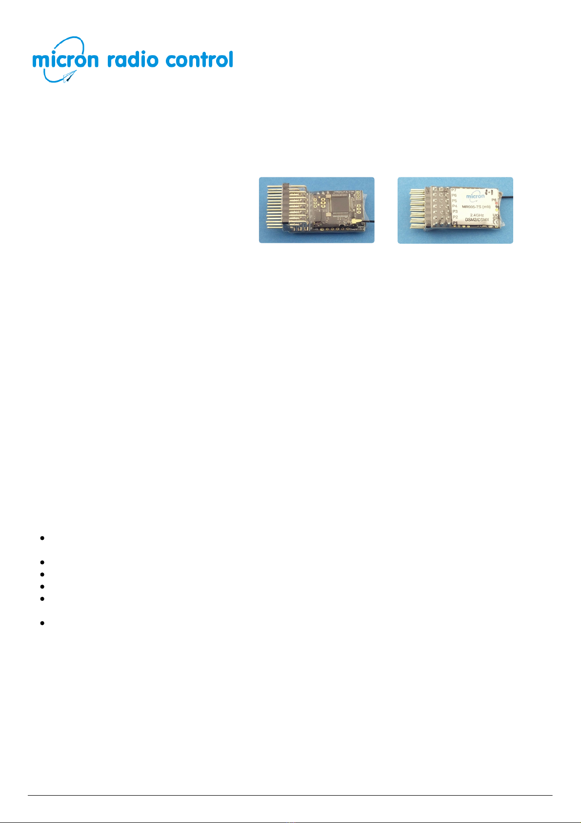
Micron MR005 User manual

MR005 Bottom
MR005 Top
Uplands House, Castle Howard Road, Malton YO17 6NJ
www.micronradiocontrol.co.uk
+44 (0)1653 696008
Micron MR005 2.4GHz DSM2/DSMX Receiver
This document is regularly updated and the most recent version may be found online at
http://micronrc.uk/mr005 where you will be able to view larger versions of the images.
MR005 is a 7 channel DSM2/DSMX
compatible receiver designed for model
railway layout control. It has 7 JR/Futaba
style pin sets to which servos or LEDs may be
connected. MR005-7S has 7 servo outputs,
MR005-7X has 7 on/off outputs (0V / 3.3V)
to which LEDs may be directly connected as
there is a 220 ohm series resistor on the receiver board. MR005 with a combination of servo and on/off
outputs, or different R/C channel to receiver output mappings, is available to special order. MR005 is
small (30x18x11mm) and it weighs 4.5g.
Each MR005 output is controlled by one R/C channel (e.g one switch on Tx27v2). Receiver state (servo
position or on/off setting) is saved once a minute and restored when the receiver is switched on. This
allows MR005 to be switched on without the transmitter being switched on.
MR005 requires binding with your transmitter before use. All versions of MR005 are manual bind so will
not go into bind mode if the transmitter is not switched on. Once bound, the transmitter should normally
be switched on before the MR005.
The MR005 free-air range, when used with a Micron low-power transmitter, is 50m-60m and
approximately 200m when used with a full-power (100mW) transmitter. This range will be reduced
indoors due to absorption by furniture / fittings and reflections from metal surfaces. Range is also
reduced if the receiver aerial is in a metal enclosure. Ideally, the aerial should be placed outside an
enclosing box and clear of any metal. The active part of the aerial is the last 30mm and this needs to
'see' the transmitter. The MR005 aerial should not be cut short or made longer as this will affect
operation of the receiver. It is important to perform a range check after installation to ensure you have
full control at all positions around the layout.
Features
Compatible with all DSM2 and DSMX transmitters with up to 10 R/C channels (only 7 used in the
standard MR005 versions, both Micron model rail and aero model stick type transmitters.
3.45V to 8.4V working voltage range - 5 NiMH cells is ideal.
All outputs have a 220 ohm series resistor which allows direct connection of a low-current LED.
Servo outputs are reversible and end-points may be adjusted.
Outputs maintain current setting on signal loss and are saved every minute so that they can be
restored next time the receiver is switched on.
The CPU LED is repeated to P8 (rear JST-ZH socket or solder pads, depending on the MR005
version).
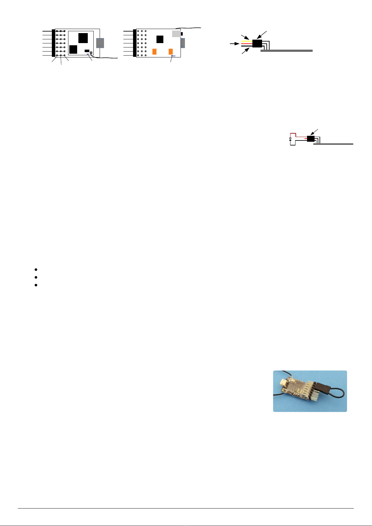
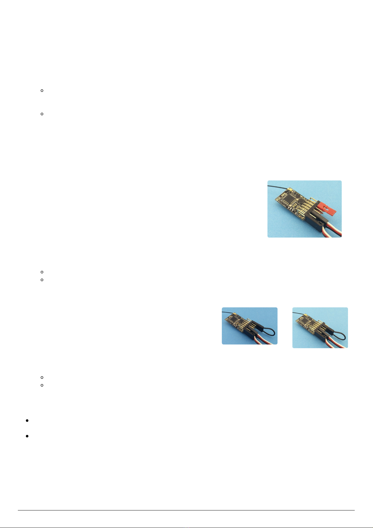
Connections and Indicators
MR005 has 7 sets of output pins which can be used for servos (MR005-7S) or LEDs for colour light
signals or trackside lighting (MR005-7X). The pin sets, numbered from the top of the diagram below, are
0.1" pitch to take standard R/C plugs.
Micron R/C, www.micronradiocontrol.co.uk, +44 (0)1653 696008 Micron MR005 2.4GHz DSM2/DSMX Receiver : 1 of 5

Manual Bind
CPU LED
Bottom
Pos
Top
P1
SigGnd RF LED
P2
P3
P4
P5
P6
P7
P8
Servo Plug
Yellow or White (Signal)
Red (Positive)
Black or Brown (Negative) Side View of MR005
MR005 can be powered from a battery of 3.45V up to 8V; use of a 4 or 5 cell NiMH rechargeable battery
or a 5V regulated power supply for permanent trackside installation. for permanent trackside installation.
The 2 standard configuration have servo or on/off switched outputs on P1 to P7:
MR005-7S: servo on P1..P7 = R/C chan 1..7
MR005-7X: on/off (0V/3.3V) on P1..7 = R/C chan 1..7
A LED is connected to the signal (top row) and negative (bottom
row) pins. There is a series 220 ohm resistor on the receiver board
so the LED may be connected directly to the receiver.
Servo Plug
LED
Side View of MR005
All have LED2 on P8, but not all receivers have a socket. Connect to the solder pads or request a socket to be
fitted. LED2 repeats the CPU LED for binding and servo adjustment feedback.
Other output configurations can be supplied to special order at no additional cost.
MR005 has 2 LED indicators, one on the top near the aerials and another on the bottom, these are labeled 'RF
LED' and 'CPU LED' on the diagram below. There are actually 2 LEDs on the bottom, but only one of them is
used.
RF LED:
indicates when a good signal is received, flashes rapidly when the rx is in bind mode and flashes slowly if
the receiver power was interrupted
CPU LED:
indicates the receiver status:
flashes slowly after switch on and waiting for a good transmitter signal
lights continously when a good R/C signal is being decoded
used for feedback when setting servo travel end points or reversing servo direction
Binding
MR005 must be bound to a transmitter before use. Once bound, MR005 remembers the transmitter identity
and searches for this when it is switched on. When binding, we recommend that servo connecting rods are
disconnected in case they are incorrectly set.
To bind a receiver, the large jumper plug supplied with the receiver is connected across the signal pins (top
row) for P5 and P7 and then the receiver is switched on with the transmitter switched off. If fitted, P5, P6 and
P7 plugs must be removed when binding.
MR005 does not support auto-bind.
Bind mode is indicated by a rapid flashing of the receiver RF LED and the
following steps should be followed to bind with your transmitter:
1. transmitter switched off
2. switch the receiver on in bind mode
3. only when the RF LED is flashing rapidly, hold down the transmitter bind button and switch on
4. wait for the transmitter to indicate that it is in bind mode and then release its bind button (the power LED
on Micron model rail transmitters will flash when binding)
5. after a short delay, the RF LED should stop flashing and go dark and, after another 4-5 seconds, both RF
and CPU LEDs will light and stay on
6. the receiver is now bound to the transmitter
If the receiver RF and CPU LEDs do not come on solid (no flash) within 10-15 seconds, the bind process has
failed. This can happen for several reasons and does not normally indicate a fault. During binding, the receiver
searches for the transmitter's signal and this can be distorted by holding the transmitter and receiver to close.
So, if you get a bind fail, try again after moving them slightly further apart or changing the relative orientation
Micron R/C, www.micronradiocontrol.co.uk, +44 (0)1653 696008 Micron MR005 2.4GHz DSM2/DSMX Receiver : 2 of 5

Select P1 to adjust
of the aerials. Binding is most reliable when no other 2.4GHz transmitters are turned on.
Reset
The receiver settings can be reset back to the as-supplied configuration using the large jumper across signal
pins P1 and P3. This removes any servo adjustment changes that have been made. To reset:
1. turn off the receiver
2. put the large jumper plug across signal pins (top row) P1 and P3
3. the CPU LED will flash once per second
4. remove the jumper plug
5. the receiver will reset and the CPU LED will flash rapidly until the receiver is switched off
Jumper Changes
This is a summary of the configuration changes that can be made using a large jumper across the signal pins:
Reset to factory setup P1 & P3
Manual bind P5 & P7
Other jumper settings are used to change servo direction and alter the servo travel end points (see below).
Servo Adjustment
Note: this section applies only to MR005-7S
Servo direction and throws (low and high end points) can be changed using the supplied small and large (bind)
jumper plugs. The method is simple and comprises 2 steps:
1. select the servo output to be adjusted using the small jumper
2. reverse the servo using the small jumper, or increase or decrease the servo throw using the large jumper
Servo reversing or end point adjustment can be performed as many times as required on the selected servo.
When complete, remove power from the receiver to stop, all changes are stored to the CPU memory. The next
time power is applied, the receiver will operate normally.
Only one servo output can be changed at a time, the method must be repeated for each servo that requires
adjustment.`
WARNING: never place the small jumper across the positive (middle row) and negative (bottom row) pins.
This will short the battery.
Step 1 - select servo output to adjust
The small jumper plug is used to select one of the outputs for adjustment; it is
placed across the wanted signal pin (top row) and the adjacent next higher
signal pin. To select P7, the small jumper is placed across signal pins P1 and P2
plus the large jumper is placed across signal pins P5 and P7. The battery plug is
then connected to a spare pin set leaving P6 and P7 free (if adjusting P1 to P5)
or P1 and P2 free (if adjusting P6 or P7). The table at the end of this section
shows which pins are to be used for adjusting the servo on a particular output
pin.
When the battery is connected, the CPU LED will show a flash count equal to the servo pin selected. If you are
attempting to select and output that is not configured as a servo, the CPU LED will show a continuous rapid
flash.
Micron R/C, www.micronradiocontrol.co.uk, +44 (0)1653 696008 Micron MR005 2.4GHz DSM2/DSMX Receiver : 3 of 5

Reverse direction of P1 servo
Decrease throw
Increase throw
Steps:
1. receiver must be bound to transmitter
2. receiver power off
3. transmitter on
4. place the small jumper (and large jumper if adjusting P7) as shown in the table at the end of this section
5. plug the battery into a free pin set (as shown in the table)
6. the CPU LED will flash a sequence to indicate the selected pin set - e.g. flash pause flash pause ... for P1,
flash flash pause flash flash pause ... for P2, and so on
if the selected output is not a servo, the LED will flash rapidly
7. remove the small jumper plug (and large jumper plug if adjusting P7) do not remove the battery
8. connect a servo, this will respond to the transmitter control
no other output pin is active
The servo output is now selected. Jumper plugs are used on P6 and P7 (or P1 and P2 if adjusting P6 or P7) to
reverse the servo or adjust the travel end points. Reversing or end point adjustment can be repeated as often
as desired while the servo is selected. To stop the process, remove power from the receiver.
Step 2 - adjust selected servo output
The selected servo may now have its direction reversed or have the travel end points adjusted:
Reverse servo direction
The small jumper plug is placed across signal pins (top row) for P6 and P7 to
reverse the servo direction or P1 and P2 to reverse a P6 or P7 servo . The
image shows a servo plugged into P1, a battery plugged into P3 and the small
jumper across P6/P7.
Steps:
1. select servo output to adjust (see above) and plug servo in
2. place the small jumper across signal pins P6 and P7
3. the CPU LED will flash rapidly
4. remove the jumper
the CPU LED will stop flashing
the servo will respond to transmitter controls in the opposite direction to previous
The servo direction will reverse each time the procedure is executed.
Adjust servo travel
The servo travel end points can be increased or decreased using
the large jumper plug on P6 (decrease) or P7 (increase). The
adjustment is done in small steps every ½ second and the CPU
LED flashes for each step. To make an adjustment:
1. move the servo to the low or high end using the
transmitter control
2. use the large jumper to make changes:
on P6 to decrease the throw
on P7 to increase the throw
3. either remove the jumper or move the servo away from the end to stop the adjustment
The CPU LED will stop flashing and the servo will stop moving when the adjustment limit is reached.
The limit for decrement is the mid point of travel so, if an end point is decreased to the maximum
amount, there will be no servo travel in that direction when the transmitter control is moved.
The limit for increment is the minimum or maximum signal value. Take care: not all servos will respond
to the maximum range of servo signal values; stop decrementing when the servo stops moving even
though the CPU LED is still flashing.
Micron R/C, www.micronradiocontrol.co.uk, +44 (0)1653 696008 Micron MR005 2.4GHz DSM2/DSMX Receiver : 4 of 5

Jumper connections for selecting a servo, reversing and adjusting travel
Servo Pin Jumper to
Select Battery Pin Reverse Inc Throw Dec Throw
P1 Small on P1/P2 P3 P6/P7 P6 P7
P2 Small on P2/P3 P4 P6/P7 P6 P7
P3 Small on P3/P4 P1 P6/P7 P6 P7
P4 Small on P4/P5 P1 P6/P7 P6 P7
P5 Small on P5/P6 P1 P6/P7 P6 P7
P6 Small on P6/P7 P4 P1/P2 P1 P2
P7 Small on P1/P2
Large on P5/P7
P4 P1/P2 P1 P2
© Micron Radio Control
Micron R/C, www.micronradiocontrol.co.uk, +44 (0)1653 696008 Micron MR005 2.4GHz DSM2/DSMX Receiver : 5 of 5
Table of contents
Other Micron Receiver manuals