micronAir MICROMISER 12 Service manual

MICROMISER 12 & 16
ATOMISERS
FOR USE ON UAVs
Operator's Handbook
and
Parts Catalogue
Micron Sprayers Limited
Bromyard Industrial Estate
Bromyard
Herefordshire HR7 4HS
United Kingdom
Telephone: +44 (0) 1885 482397
Fax: +44 (0) 1885 483043
Web site: www.micron.co.uk
Iss 1W
04/2021

TABLE OF CONTENTS
1. INTRODUCTION...........................................................................................1
2. SPECIFICATION...........................................................................................2
3. INSTALLATION.............................................................................................4
3.1. Atomiser........................................................................................4
3.2. Liquid Feed ...................................................................................4
3.3. Motor Venting................................................................................6
3.4. Electrical Connections...................................................................7
3.4.1. Power Supply........................................................................7
3.4.2. Atomiser Speed Control (Micromiser 12 Only)......................9
3.4.3. Atomiser Speed Output.......................................................10
3.4.4 Interface with Flight Control System....................................11
4. OPERATION ...............................................................................................12
5. HEALTH & SAFETY....................................................................................12
6. CALIBRATION ............................................................................................13
6.1. Flow Rate....................................................................................13
6.2. Spray Droplet Size ......................................................................14
7. MAINTENANCE ..........................................................................................15
7.1. Fault Finding ...............................................................................17
8. PARTS LISTS .............................................................................................19
8.1. Micromiser Atomiser ...................................................................19
8.2. Cable Assembly ..........................................................................19
9. CONVERSION FACTORS ..........................................................................20
APPENDIX I – Interface with Flight Control System....................................21

MICRONAIR MICROMISER 12 & 16 ATOMISERS FOR USE ON UAVs
1. INTRODUCTION
Micronair Micromiser atomisers can be installed on Unmanned Aerial Vehicles
(UAVs) to spray a wide range of liquids in droplets of precisely controlled size.
Applications include spraying of agricultural crops, migrant pests (locusts etc) and
mosquito control using adulticides or liquid larvicides.
Micromiser atomisers are intended for Ultra Low Volume (ULV) and Low Volume
(LV) applications.
Spray droplets are produced by a rotating toothed disc. Droplet size is determined
by the rotational speed of the disc, which is driven by a 24 V DC brushless motor for
maximum reliability.
Unlike hydraulic spray nozzles, the atomiser does not require a high liquid pressure
to operate and there are no small internal orifices to block. This allows the atomiser
to handle viscous materials and liquids with a high solids content.
Each atomiser can operate at flow rates of up to 300 ml/min, with the minimum flow
rate determined only by the liquid delivery system used.
The brushless motor has integrated drive electronics and requires only a 24 V DC
supply to operate. A pulse output is provided for the measurement of disc speed or
for monitoring of atomiser performance.
The atomiser is available in two versions:
Micromiser 12 with rotational speed variable over the range of 1,500 – 12,000 RPM
to produce spray droplets of 60 – 300 µm VMD. This atomiser should be used for
application on crops and ground targets. The atomiser motor incorporates closed-
loop speed control to ensure constant rotational speed regardless of liquid flow rate.
The rotational speed is set by means of an external potentiometer or voltage input.
This allows the spray droplet size to be pre-set or varied by a customer provided
control system.
Micromiser 16 with a fixed rotational speed of 15,000 – 16,000 RPM to produce
small spray droplets of 45 – 60 µm VMD. This atomiser should be used for space
spraying application of insecticides to control flying insects such as mosquitoes

2
MICRONAIR MICROMISER 12 & 16 ATOMISERS FOR USE ON UAVs
2. SPECIFICATION
Dimensions: Length 105 mm (including atomiser disc but excluding
connector), diameter 58 mm (max), 32 mm (motor
housing)
Weight: 240 g
Mounting: By two M4 tapped holes
Liquid feed connection: Push-in fitting for 6 mm O/D rigid plastic tube
Vent connection: Push-in fitting for 3 mm O/D rigid plastic tube
Electrical connection: 4 pin M12 sealed connector (A-coding)
Environmental protection: IP65 (with motor vent tube connected)
Ambient temperature: -10 – +40 ºC nominal (minimum temperature must not
be below freezing point of liquid being sprayed)
Input voltage: 24 V DC
Power consumption: 1.5 – 10 W (dependant upon disc speed and liquid flow
rate)
Motor rating: Continuous
Disc speed: Micromiser 12: adjustable 1,500 – 12,000 RPM
Micromiser 16: fixed 15,000 – 16,000 RPM
Speed output: 5 V pulse output (one pulse/disc revolution)
Spray droplet size: Micromiser 12: 60 – 300 µm VMD
Micromiser 16: 45 – 60 μm VMD
(dependant upon disc speed & liquid properties)
Liquid flow rate: 0 – 300 ml/minute

3
MICRONAIR MICROMISER 12 & 16 ATOMISERS FOR USE ON UAVs
Fig 1. – Micromiser Atomiser
Fig 2. – Micromiser Atomisers on Multi-rotor UAV

4
MICRONAIR MICROMISER 12 & 16 ATOMISERS FOR USE ON UAVs
3. INSTALLATION
3.1. Atomiser
Many different configurations of UAV (multi-rotor, fixed-wing etc) can be used for
aerial spraying. The following points provide general guidance on the installation of
Micromiser atomisers but are not intended to make specific recommendations. It is
the responsibility of the installer to establish the optimum placement of atomisers
and to carry out trials to assess the spray distribution on the target.
Atomisers are normally mounted on booms extending laterally from the structure
of a multi-rotor UAV or below and slightly behind the trailing edge of a fixed-wing
UAV.
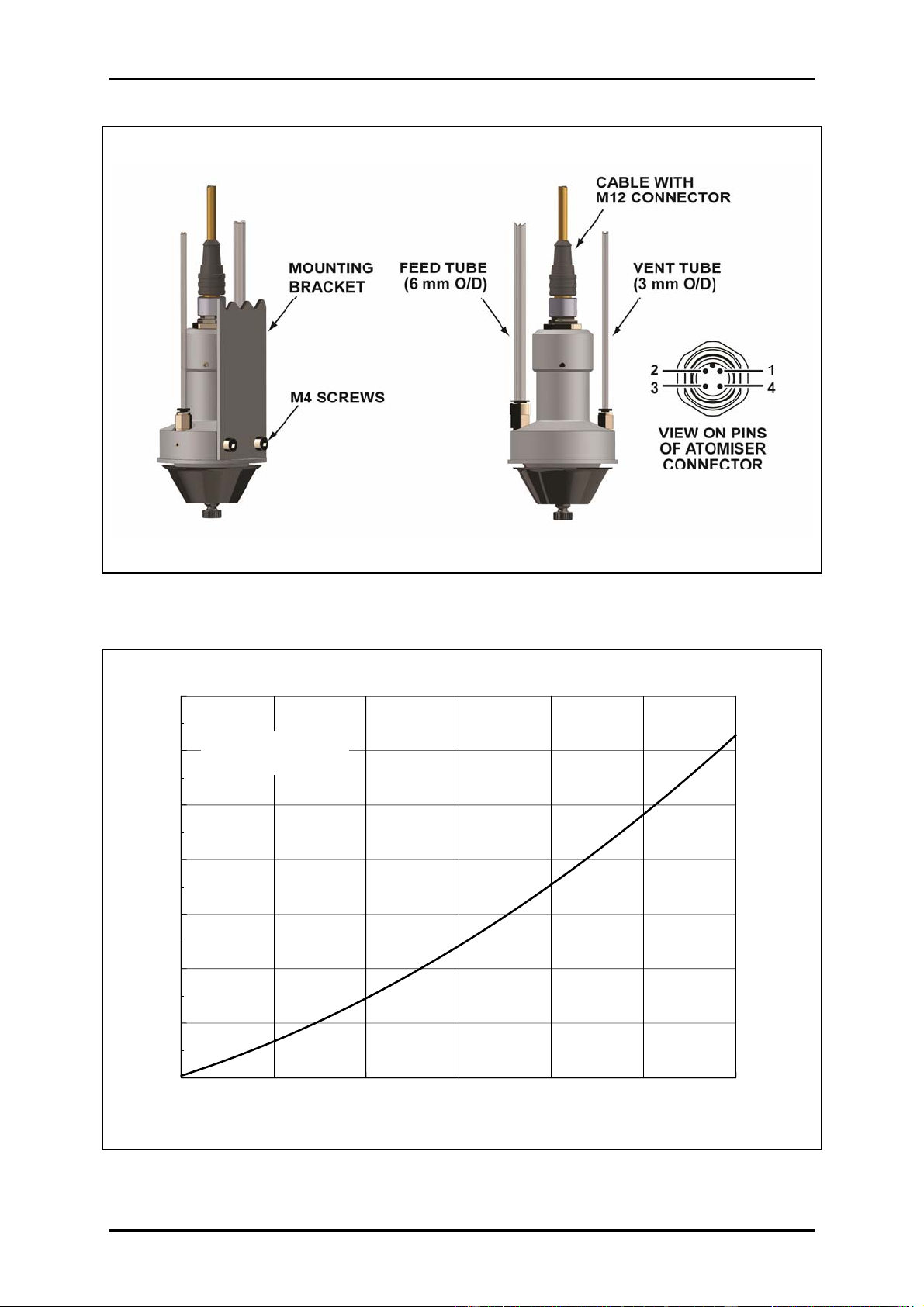
Each atomiser should be attached to a mounting bracket on the boom with two
M4 screws in the tapped holes in the side of the atomiser housing (25 mm
between hole centres) as shown in Fig. 3. M4 x 12 mm stainless steel cap head
screws are supplied with the atomiser and these are suitable for a bracket with a
thickness of 2 – 6 mm. If alternative screws are used these should also be
stainless steel.
The boom structure and bracket must be sufficiently rigid to avoid excessive
vibration in flight.
The booms must be positioned to provide adequate clearance under the
atomisers whilst the UAV is resting on the ground or manoeuvring during take-off
or landing. If necessary, the booms should have sufficient dihedral angle to
maintain ground clearance.
The orientation of the atomisers depends upon the direction and speed of flight of
the UAV. In the case of a fixed-wing UAV or a multi-rotor UAV that flies in only
one direction and sprays at a relatively high airspeed (>10 km/hr) the atomisers
should be mounted with the axis of the motor horizontal with the disc at the rear.
This is similar to the installation of rotary atomisers on conventional agricultural
aircraft and helicopters. In the case of a UAV that reverses its direction of flight
(relative to the airframe) at the end of each spray run or a UAV that will spray at
low airspeeds the atomisers should be mounted with the axis of the motor vertical
with the disc downwards.
3.2. Liquid Feed
The liquid feed to the atomiser is by a tube connected to the inlet fitting on the face
of the housing as shown in Fig. 3. The standard fitting supplied with the atomiser is
a push-fit type that accepts a 6 mm outside diameter flexible tube. If required, this
fitting can be replaced with an alternative type with a M5 male thread to screw into
the atomiser housing.
Spray liquid is fed to the atomiser by means of a pump provided by the installer.
This can either be a positive displacement type (eg a gear pump) with a speed
controller to adjust the output to provide the required total flow rate or a centrifugal or
diaphragm type with a flow control valve. It is recommended that the flow control
valve should be fitted in a by-pass line to return excess flow from the pump to the
tank.

5
MICRONAIR MICROMISER 12 & 16 ATOMISERS FOR USE ON UAVs
Fig. 3 – Mounting of Atomiser and Connections
0 100 200 300
FLOW (ml/MIN)
0
50
100
150
200
250
300
350
INLET PRESSURE (mm HEAD OF WATER)
PRESSURE MEASURED
AT INLET WITH WATER
Graph 1 – Inlet Pressure vs Flow Rate

6
MICRONAIR MICROMISER 12 & 16 ATOMISERS FOR USE ON UAVs
As there are no small orifices in the atomiser, the liquid pressure required at the
atomiser inlet is very low – see Graph 1. If multiple atomisers are installed It is
recommended that a restrictor orifice should be fitted in the feed line to each to
create some back-pressure and to balance the flow between atomisers.
The system should incorporate a filter before the inlet to the pump to reduce the risk
of blockages, particularly if restrictor orifices are installed.
3.3. Motor Venting
In order to avoid condensation inside the motor, the atomiser is fitted with a vent port
that must be connected to a tube that can supply air from an area away from spray
droplets – see Fig. 3. The standard vent fitting supplied with the atomiser is a push-
fit type that accepts a 3 mm outside diameter flexible tube. If required, this fitting can
be replaced with an alternative type with a M5 male thread to screw into the atomiser
housing.
The rotation of the atomiser disc creates a small negative pressure inside the motor
housing and this is sufficient to draw air into the vent port. The tube must run
upwards throughout its length so as to avoid any loops that could trap moisture – see
Fig. 4. On a multi-rotor UAV the vent tubes should be run to a point towards the top
of the airframe. On a fixed-wing UAV the tubes should run forwards to a point clear
of the spray boom. If necessary, the open ends of the tubes should be under a
cover to prevent ingress of water from rain or washing.
Fig. 4 – Orientation of Atomiser Vent Tube

7
MICRONAIR MICROMISER 12 & 16 ATOMISERS FOR USE ON UAVs
3.4. Electrical Connections
The atomiser is fitted with a sealed 4 pin male M12 connector (A-coding). Pin
numbers are as shown in Fig. 3 and pin assignments are as follows:
Pin Number Wire Colour* Function
1 Brown +24 V DC supply
2 White Tacho (RPM) pulse output
3 Blue Ground
4 Black Speed control input (Micromiser 12 only)
*When using standard moulded cable
It is recommended that the cable with moulded connector supplied with the atomiser
should be used to prevent moisture ingress. If an alternative re-wireable connector
is used it must be filled with non-corrosive silicone rubber compound.
The cable used to connect the atomiser to the power supply or controller should
have a minimum conductor size of 0.33 mm2(22 AWG).
3.4.1. Power Supply
Both the Micromiser 12 and Micromiser 16 atomisers require a 24 V DC power
supply. This will normally be provided by the main battery of an electrically powered
UAV. If the available supply is greater than 24 V it will be necessary to install a step-
down (buck) voltage converter. If the available supply is less than 24 V it will be
necessary to install a step-up (boost) voltage converter. One converter can be used
to supply several atomisers connected in parallel provided that its output current
rating is at least 0.5 A per atomiser. Small buck and boost converter modules are
readily available from electronic equipment suppliers and internet sellers.
IMPORTANT: Micromiser atomisers must be operated with a smooth DC power
supply. Under no circumstances should a pulsed (PWM) power supply or voltage
converter (eg a PWM motor speed controller) be used. A pulsed power supply will
damage the internal motor controller and its use will void all warranties.
The supply to the voltage converter (if fitted) or atomisers must be protected by a
fuse or circuit breaker. The recommended rating is 1 A per atomiser. Each atomiser
motor incorporates a controller with a slow-start ramp, so there is no significant
current surge when the motor starts.
Graph 2 shows the relationship between current consumption, atomiser rotational
speed and liquid flow rate for the Micromiser 12. Graph 3 shows the relationship
between current consumption and liquid flow rate for the Micromiser 16 when
operated from a 24 V supply.

8
MICRONAIR MICROMISER 12 & 16 ATOMISERS FOR USE ON UAVs
1000 2000 3000 4000 5000 6000 7000 8000 9000 10000 11000 12000
ATOMISER RPM
0
50
100
150
200
250
300
350
400
450
500
MOTOR CURRENT (mA)
200 ml/min
300 ml/min
100 ml/min
Dry
Graph 2 – Current Consumption of Micromiser 12 vs Atomiser RPM and Flow Rate
0 100 200 300
FLOW (ml/MIN)
0
100
200
300
400
500
MOTOR CURRENT (mA)
Graph 3 – Current Consumption of Micromiser 16 vs Flow Rate at 24 V Input

9
MICRONAIR MICROMISER 12 & 16 ATOMISERS FOR USE ON UAVs
3.4.2. Atomiser Speed Control (Micromiser 12 Only)
The speed of the Micromiser 12 atomiser is determined by the voltage on pin 4 of the
motor connector. This pin is pulled up to the internal +5 V supply of the motor
controller by a 1 K Ohm resistor and an external resistor between pin 4 and ground
forms a potential divider to set the control voltage. Fig. 5 shows a simplified
schematic of the control input.
The external speed control resistor can be either an adjustable potentiometer or a
fixed resistor if the atomiser is always to operate at a set speed. Graph 4 shows the
relationship between atomiser RPM and the external speed control resistor value. It
is recommended that a 10 K Ohm potentiometer is used if the atomiser is to be
operated over its entire speed range.
The minimum speed of the Micromiser 12 is 1,500 RPM. This will be achieved with
a control resistor value of 47 Ohms. The atomiser will not rotate if the control
resistor is below 47 Ohms. It is recommended that a 47 Ohm resistor should be
fitted between the lower side of the potentiometer and ground – see Fig. 5. This
ensures that the atomiser runs at its minimum speed with the potentiometer set fully
anti-clockwise.
The internal motor controller of the Micromiser 12 atomiser operates in closed loop
mode and compensates automatically for the load of liquid on the disc. The disc
speed therefore remains constant over the full range of flow rates. The disc speed
can be adjusted with the atomiser running dry and will not change under load.
0 2000 4000 6000 8000 10000 12000 14000
ATOMISER RPM
0
1
2
3
4
5
6
7
8
9
10
CONTROL RESISTOR (K OHM)
Graph 4 – Micromiser 12 Atomiser RPM vs Control Resistor Value

10
MICRONAIR MICROMISER 12 & 16 ATOMISERS FOR USE ON UAVs
Fig. 5 – Schematic of Speed Control for Micromiser 12
3.4.3. Atomiser Speed Output
A pulse output is provided to enable the rotational speed of the atomiser to be
measured without the use of an external tachometer or stroboscope on the disc.
The atomiser speed can be measured either with a portable instrument (eg a
laboratory frequency counter or multimeter with a frequency function) or by a
permanently installed indicator calibrated to read RPM directly.
The speed output is provided on pin 2 of the atomiser connector (white wire in
standard moulded M12 connector). The specification of this output is:
Scaling: One pulse per revolution
Pulse amplitude: +5 V relative to ground (pin 3)
Minimum load impedance: 50 K ohm
Maximum load capacitance: 0.01 μF
IMPORTANT: connecting an instrument with a lower impedance or higher
capacitance loading will impair the efficiency of the integrated motor drive circuit and
could cause permanent damage.
If a multimeter or other frequency measuring instrument is used to measure the
motor speed in Hz the atomiser speed (RPM) is given by:
Motor speed (RPM) = Frequency (Hz) x 60

11
MICRONAIR MICROMISER 12 & 16 ATOMISERS FOR USE ON UAVs
3.4.4. Interface with Flight Control System
It is possible to interface Micromiser atomisers with a suitable UAV flight control
system so that the atomiser motors can be started and stopped in flight and (if
required) the atomiser rotational speed can be changed to produce the required
spray droplet size. The control of the atomisers will normally be in conjunction with
switching of the pump or flow to the atomisers.
The configuration of the interface will depend upon the flight control system and
operational requirements. The following points are provided for general guidance
only:
The atomiser motors can be turned on and off by switching the 24 V DC power
supply with a relay or semiconductor device (eg a suitably rated MOSFET).
The atomiser motors must be turned on at least 2 seconds before starting the
pump and turned off after the pump has been stopped and liquid flow has ceased
– see Section 4.
It is not normally necessary to stop the rotation of the atomisers during turns
within the spray area.
When possible, it is recommended that the atomisers are not rotating during take-
off or landing to minimise the risk of damage to the discs from contact with foliage
on the ground etc.
In normal operation there should be an interlock to ensure that there cannot be
flow to the atomisers unless they are rotating. However, the control system
should incorporate a function or switch to enable the pump whilst the atomisers
are not rotating for calibration on the ground – see Section 5.1.
If using a Micromiser 12 atomiser its rotational speed can be set by varying the
voltage on the control input (pin 4). This can be achieved by means of a
transistor and voltage feedback as shown in the example schematic in Appendix
I. Note that this arrangement requires a DC control voltage from the flight control
system (typically provided by a D/A converter). Under no circumstances should
the control voltage be provided directly from a pulsed output (eg a PWM motor
controller). Should the control system provide a pulsed output this must be
filtered to provide a DC voltage with a maximum of 10 mV P/P ripple.
If required, the atomiser speed output (pin 2) can be fed to the flight control
system. This can be used either for closed-loop speed control or as an indication
that the atomiser is rotating. The absence of pulses on this output whilst the
atomiser is powered can be used to indicate a fault. The input to the flight control
system must have a high impedance and low capacitance – see Section 3.4.3. If
necessary, a buffer or level converter must be used between the atomiser output
and the control system input as shown in Appendix I.

12
MICRONAIR MICROMISER 12 & 16 ATOMISERS FOR USE ON UAVs
4. OPERATION
The atomiser is provided with a clip-on plastic protective cap. This must be removed
before operation and should be re-fitted if the atomiser is not to be used for a
prolonged time or before the UAV is transported.
The atomiser disc must be running at its required speed before the liquid flow
commences. The atomiser motor can take up to two seconds to reach its final speed
so there should be a delay of a minimum of two seconds between starting the motor
and starting the liquid feed to the atomiser.
The liquid flow to the atomiser must be stopped before the motor is stopped. The
time for the liquid flow to cease will depend upon the diameter, length and orientation
of the feed tube. There must be a sufficient delay between stopping the liquid flow
and stopping the atomiser to allow the feed tube to empty completely.
IMPORTANT: the liquid flow to each atomiser must not exceed 300 ml/min.
Operation at a higher flow rate could result in damage to the atomiser motor.
5. HEALTH & SAFETY
Legislation regarding the application of chemicals which are potentially harmful to
individuals or the environment varies considerably between countries. Operators
using chemicals and equipment must ensure they are working within the regulations
applicable to their area.
Irrespective of legislation, Micronair advise the users of their equipment that all
possible care must be taken to ensure the health and safety of the user and
personnel in the vicinity of the spraying operation.
The following recommendations are for guidance only and do not exclude any
statutory requirement:
1. The application of each chemical should follow the recommendations of the
manufacturer. Extreme care should be taken to prevent chemical reaching
the operator or any other people, animals or neighbouring crops where
contamination could have an adverse effect.
2. Ensure that the equipment is correctly calibrated for the chemical being used.
3. Suitable clothing, gloves, eye protection and masks must be worn when
working with or near toxic chemicals and operators must adhere to all relevant
handling precautions and regulations.
4. The entire spray system and all ancillary equipment must be thoroughly
washed out after use or before maintenance.
5. All chemical residues must be safely stored or disposed of.
6. All used chemical containers must be safely disposed of in accordance with
local regulations and requirements.
7. First aid and washing facilities must always be available and personnel must
be trained in their use.

13
MICRONAIR MICROMISER 12 & 16 ATOMISERS FOR USE ON UAVs
6. CALIBRATION
For correct operation, both the liquid flow rate and the spray droplet size must be
adjusted according the requirements of the application.
6.1. Flow rate
The flow of liquid to the atomisers is controlled by a valve, metering pump etc
provided by the installer. See Section 3.2 for further details.
The total flow rate (l/minute) from the UAV is determined by the area treated per
minute (ha/min) and the required application rate of the product (l/ha).
The area treated per minute depends upon the spraying speed (km/hr) and the
distance between successive spray tracks (track spacing in m):
Area treated/min (ha/min) = spraying speed (km/hr) x track spacing (m)
600
The total flow from the UAV is given by the area treated/minute (ha/min) multiplied
by the application rate on each hectare (l/ha), so:
Flow (l/min) = spraying speed (km/hr) x track spacing (m) x application rate (l/ha)
600
Example:
A UAV fitted with four Micromiser 12 atomisers is to apply 10 l/ha using a spraying
speed of 12 km/hr and a track spacing of 5 m, so:
Total flow from UAV = 12 km/hr x 5 m x 10 l/ha = 1.0 l/min
600
Flow per atomiser = total flow ÷number of atomisers = 1.0 ÷4 = 0.25 l/min
The flow rate from each atomiser can be measured as follows:
1. Remove the discs from all atomisers as described in Section 6.
2. Place a bucket or other suitable receptacle under each atomiser.
3. Fill the spray tank with the actual product to be sprayed (note that the flow rate
may change according to the viscosity of the product).
4. Turn on the pump and wait for a steady stream of liquid to flow from each
atomiser.
5. Place an empty container under each atomiser to collect liquid for a measured
time (typically 1 minute, but two minutes can be used for low flow rates).
6. Turn off the pump.

14
MICRONAIR MICROMISER 12 & 16 ATOMISERS FOR USE ON UAVs
7. Measure the volume collected from each atomiser by pouring the liquid into a
calibrated measuring cylinder or jug.
8. Calculate the flow rate from each atomiser (l/min) by dividing the volume
collected (l) by the time (min).
9. Add the flow rates (l/min) from all atomisers together to obtain the total flow rate
from the UAV.
10. Adjust the flow rate as necessary and repeat steps 4 – 9 to obtain the required
total flow rate as calculated above.
6.2. Spray Droplet Size
The diameter of the spray droplets produced by the atomiser disc is determined by
the rotational speed of the disc, the liquid flow rate and the physical properties of the
spray liquid.
Graph 5 shows the measured VMD (Volume Median Diameter) of spray droplets
from the Micromiser 12 at rotational speeds of 1,500 – 16,000 RPM when spraying
plain water. Graph 5 shows the relationship between measured VMD (Volume
Median Diameter) of spray droplets and liquid flow rate from the Micromiser 16 when
operated from a 24 V supply. These graphs are intended as a guide only as the
droplet size is influenced by the physical properties of the liquid being sprayed. In
general the addition of a surfactant to reduce surface tension will reduce droplet size
by up to 15%. The droplet size when spraying formulations based on light oils will be
about 15 – 20% smaller than shown.
1000 2000 3000 4000 5000 6000 7000 8000 9000 10000 11000 12000
ATOMISER RPM
0
100
200
300
400
SPRAY DROPLET SIZE (µm VMD)
300 ml/min
100 ml/min
Graph 5 – Spray Droplet Size vs Atomiser RPM for Micromiser 12

15
MICRONAIR MICROMISER 12 & 16 ATOMISERS FOR USE ON UAVs
0 100 200 300
FLOW RATE (ml/MIN)
0
10
20
30
40
50
60
70
SPRAY DROPLET SIZE (µm VMD)
Graph 6 – Spray Droplet Size vs Flow Rate for Micromiser 16 with 24 V Supply
When using a Micromiser 12 atomiser the atomiser speed must be set either by an
external control resistor or a potentiometer as described in Section 3.4.2 or by the
UAV flight control system as described in Section 3.4.4.
The Micromiser 16 atomiser is intended to operate only at its maximum speed to
produce the smallest possible spray droplets. It must be used with a 24 V DC power
supply and the droplet size will be as shown in Graph 6.
7. MAINTENANCE
The rotating disc of the atomiser must be kept clean at all times. Contamination of
the grooves on the inner surface of the disc or of the teeth on the periphery will result
in poorly controlled spray droplet size and can cause vibration.
The procedure to clean the atomiser disc is as follows:
1. Disconnect power from the atomiser.
2. Whilst holding the disc with one hand, use the other to unscrew the knurled
knob of the locking collet at the bottom of the disc by about four turns.
3. Pull on the knurled knob to slide the disc off the motor shaft.
4. Immerse the disc in water or a suitable solvent for the liquid that had been
sprayed and remove any residue by brushing along the grooves and between
the teeth with a soft brush. Do not use a metal or other hard brush as this could
damage the disc.

16
MICRONAIR MICROMISER 12 & 16 ATOMISERS FOR USE ON UAVs
5. Dry the disc with a soft lint-free cloth or compressed air.
6. Inspect the teeth of the disc. If these are worn or damaged the disc should be
replaced. The disc is a consumable item and replacements are available from
Micron Sprayers Ltd, part number CBP3324.
7. Replace the disc on the motor shaft and slide it on as far as possible.
8. Hold the disc in one hand whilst simultaneously pushing it towards the atomiser
body and tightening the knurled knob with the other. The knob should be finger
tight, but do not over-tighten with pliers etc.
9. If the atomiser is not to be used immediately, fit the plastic protective cap over
the disc.
Liquid is fed to the atomiser disc through a feed nozzle. If this nozzle should
become blocked, the procedure to clean it is as follows:
1. Disconnect power from the atomiser.
2. Remove the atomiser disc as described above.
3. Using a 5 mm A/F socket or box spanner (wrench), unscrew the feed nozzle
from the housing.
4. Immerse the nozzle in water or a suitable solvent for the liquid that had been
sprayed and remove any blockage or residue by inserting a piece of wire into
the bore of the nozzle
5. Dry the nozzle with a soft cloth or compressed air.
6. If necessary, remove the liquid feed tube from the atomiser and remove any
residue or blockage from the inside of the tube and the hole through the
housing.
7. Replace the feed nozzle in the housing.
8. Replace the atomiser disc as described above
The outside surfaces of the atomiser can be cleaned with a cloth moistened with
water or a suitable solvent for the liquid that had been sprayed.

17
MICRONAIR MICROMISER 12 & 16 ATOMISERS FOR USE ON UAVs
7.1. Fault Finding
Problem Possible Cause Action
Blocked feed nozzle Remove feed nozzle and
clean
No liquid flow from
atomiser
Blocked or defective flow
control valve or pump
Remove feed tube from
fitting on atomiser and
check flow rate; clean or
repair valve or pump
Excessive flow rate Reduce the liquid flow rate
to 300 ml/min or less
Liquid drips from flange of
atomiser feed body
Contaminated or damaged
disc
Clean disc or replace if
damaged
Faulty power supply, cable
or connector
Remove connector from
atomiser and check
voltage between pins 1 &
3 of cable connector;
locate external fault and
repair
Disc does not rotate
Debris between edge of
disc and feed body or
alongside feed nozzle
Check disc for free
rotation, remove disc and
clean as necessary
Low voltage on speed
control input
Check voltage between
pins 3 & 4 of cable
connector (atomiser will
not rotate when <0.25 V),
locate external fault and
repair
Defective atomiser motor Replace motor assembly
or return atomiser to
Micron Sprayers Ltd for
repair
Atomiser vibrates whilst
operating
Contaminated or damaged
atomiser disc
Clean disc or replace if
damaged

18
MICRONAIR MICROMISER 12 & 16 ATOMISERS FOR USE ON UAVs
Fig. 6 – Components of Micromiser Atomiser
Other manuals for MICROMISER 12
1
This manual suits for next models
1
Table of contents