6.1.4 PPS-20 Linear Motor MII 6000 Digital Encoder 18
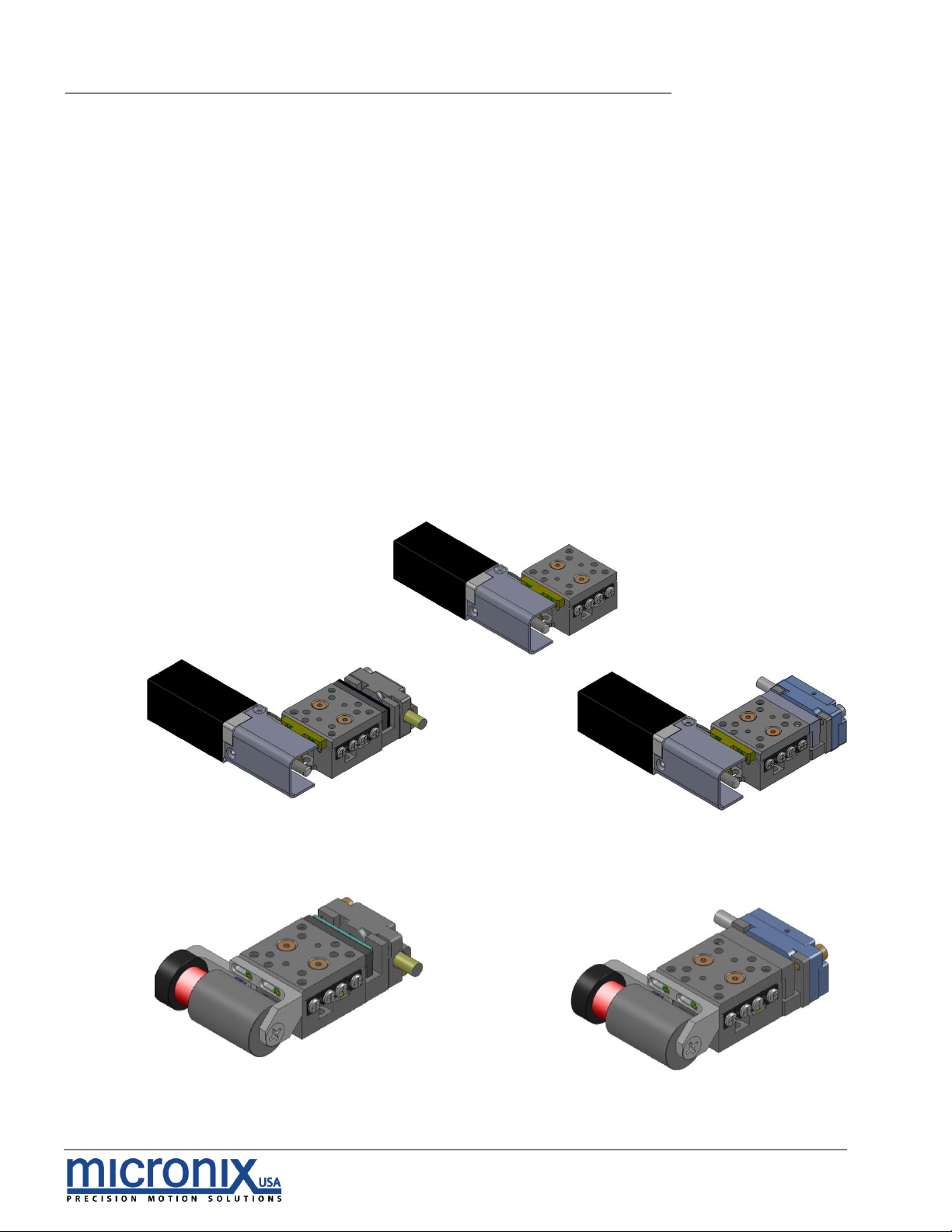
7. Stacking Configurations
19
7.1 Configuration Examples 19
8. Supplementary Information
20
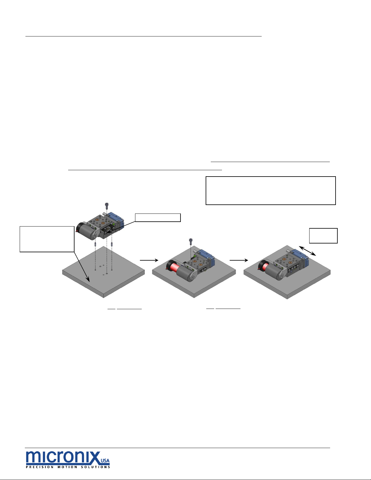
8.1 Maintenance 20
8.2 Units and Conventions 20
8.3 Accessories 20
A. Appendix
21
A.1 Stepper Motor 21
A.1.1 Standard Atmospheric DB-9 Male Motor Connector 21
A.1.2 Stepper Motor Specifications 21
A.2 Linear Voice-Coil Motor 22
A.2.1 Standard Atmospheric DB-9 Male Motor Connector 22
A.2.2 Linear Motor Specifications 22
A.3 Magnetic (Hall Effect) Limit Switches 24
A.4 Open Loop Vacuum Wiring Diagram 25
A.4.1 Straight Through 9-Pin Feed Through 25
A.5 Using an Analog Encoder 26
A.5.1 Analog Encoder Overview 26
A.5.2 Encoder Pin-Out 26
A.5.3 Operating and Electrical Specifications 26
A.5.4 Analog Output (Pins 1,2,6 and 7) 26
A.5.5 Index Window (Pins 3) 27
A.5.6 Resolution 27
A.5.7 Analog Encoder Wiring Diagram 27
A.6 Using the Digital Encoder Module 28
A.6.1 Encoder Module Pin-out 28
A.6.2 Operating and Electrical Specifications 29
A.6.3 Output Signals & Signal Termination for A quad B, Index and limits 29
A.6.4 Resolution 29
A.6.5 MII 6000 Digital Encoder Wiring Diagram 31
A.6.6 Straight Through 25-Pin Feed Through 32