Newport TSP Series User manual

1
Newport Corporation TSP Stage Series
TSP Series
Precision Linear Stages
Newport Corporation
1791Deere
P.O. Box 19607
Irvine, CA 92606-92623
Tel: 949-863-3144
Fax: 949-253-1800
www.newport.com

2
Newport Corporation TSP Stage Series
Warranty
Newport Corporation warrants its product to be free of defects in material and workman-
ship for a period of twelve (12) months from the date of shipment. During the warranty
period, Newport will repair or replace (at Newport’s discretion) any component within its
product that fails to adhere to published specifications (for standard product) or specifi-
cations in the quotation (for custom/special product).
For warranty service requiring return of a product to Newport, the item(s) must be re-
turned to our Service Center, with all shipping, taxes, or duty charges prepaid unless
special arrangements have been approved beforehand by Newport. The location of
services performed under warranty will be determined by Newport.
If using controller electronics other than Newport’s, the liability of the product rests with
the customer if upon performance evaluation of the stage there are no anomalies exhib-
ited with Newport’s electronics.
Warranty Limitations
The foregoing warranty shall not apply to defects resulting from:
a. Components and accessories manufactured by companies other than Newport,
which causes damage to Newport’s products, nor does Newport’s warranty cover
the cost of the customer’s time and expenses incurred in diagnosing, repairing
and handling Newport’s warranty related issues.
b. Improper or inadequate maintenance by the buyer not in adherence with
Newport’s guidelines.
c. Customer-supplied interfacing.
d. Operation outside the environmental specifications of the product.
e. System malfunctions that are related to or caused by software misuse.
f. Improper site preparation and mainenance of unauthorized product modification
or misuse.
g. Warranty void if not delivered by an authorized Newport Corp distributor.
Newport assumes no liability for customer-supplied material. The obligations of
Newport are limited to repairing or replacing, without charge, equipment which
proves to be defective during the warranty period only. The warranty on parts
purchased after the expiration of the original warranty is ninety (90) days. Our
warranty does not cover damages due to misuse, negligence or accidents, or
damages due to installation, repairs or adjustments not specifically authorized
by Newport Corp.

3
Newport Corporation TSP Stage Series
STATEMENT OF CALIBRATION
This instrument has been inspected and tested in accordance with specifications published by
Newport Corp.
The accuracy and calibration of this instrument (where applicable) is traceable to the National
Institute for Standards and Technology through equipment which is calibrated at planned inter-
vals by comparison to the certified standards maintained at Newport Corp.
ACCURACY AND REVISIONS
The information in this document has been checked and is believed to be entirely reliable.
However, no responsibility is assumed for inaccuracies or inadvertent omissions. Furthermore,
Newport Corp. reserves the right to make changes to any product herin to improve reliability,
function or design.
USE OF THIS MANUAL
Please read through this manual carefully before using the equipment provided. It should be
noted that if the equipment is used in a manner other than that specified by this manual, per-
sonal injury or damage to the equipment may be incurred.
SAFETY CONSIDERATIONS
Hazard Warning Labels
The hazard warning labels pictured below are affixed to some Newport equipment. In Figure 1
below, is a Pinch Point warning label. This indicates that injury could occur if extremities are
placed between moving components.
Figure 1

4
Newport Corporation TSP Stage Series
Abbildung 1. Quetschgefahr
Figura 1. Riesgo de Aplastamiento
Figue 1. Risque d’écrasement
In Figure 2 below, is the Electrical Hazard warning label. This is to indicate that injury, such as
electric shock, burns or permanent damage to the equipment could occur if the component
comes into contact with other objects or with the user.
Figure 2
General Safety Precautions
Abbildung 2. Elektroshockgefahr
Figura 2. Riesgo Eléctrico
Figue 2. Risque électrique
Disconnect power to motorized equipment under the following circumstances:
If the unit has been exposed to rain or excessive moisture, or if liquids are spilled on it.
If the unit has been dropped or the case is damaged.
If you suspect service or repair is required.
Whenever you clean the case.

5
Newport Corporation TSP Stage Series
Achtung
Die Stromversorgung motorbetriebener Geräte is in folgenden Situationen zu
unterbrechen:
· Wenn das Gerät Regen oder übermäßigerFeuchtigkeit ausgesetzt ist,
oder wenn Flüssigkeiten in das Gerät geraten sind.
· Wenn das Gerät fallengelassen wurde oder das Gehäuse beschädigt ist.
· Wenn dasangenommen wird, daß Service - oder Reparaturarbeiten
erforderlich sind
· Wenn das Gerät gereinigt wird.
Advertencia
Desconecte el equipo motorizado de la alimentación CC bajo las siguientes
circunstancias:
· Si se expone la unidad alluvia, humedad excesiva o si le cae encim algún
líquido.
· Si la unidad se ha caído o se ha dañado su alojamiento.
· Si se sospecha que requiere mantenimiento o reparción.
· Cada vez que se limpie el alojamiento.
Attention
Débranchez l'alimentation secteur de l'appareil de pilotage dans les cas
suivants:
· Si l'équipement a été exposé à la pluie, à une humidité excessive ou à des
projections de liquide.
· Si l'équipement a subit un dommage durant le transport
(chute ou emballage abîmé).
· Si vous estimez que l'équipement a besoin d'une réparation.
· Chaque fois que vous nettoyez l’équipement.

6
Newport Corporation TSP Stage Series
To avoid hazardous situations and to protect the equipment from danger, observe
the following recommendations:
Do not make any modifications or parts substitutions to the units.
Do not touch, directly or with other objects, live circuits inside motorized units.
Do not operate the units in an explosive atmosphere.
Do not expose the units to excessive moisture (>75% relative humidity).
UNPACKING AND INSPECTION
All Newport products are carefully assembled, tested and inspected before shipment.
Upon receiving this product, please check for any obvious signs of physical damage
that might have occurred during shipment. Report any such damage to the shipping
agent immediately. Retain the original packaging materials in case reshipment
becomes necessary.
If a Newport product must be returned, the following information is needed for proper shipment
back to Newport:
a. Unit Model Number
b. Unit Serial Number
c. Reason for return.
A Return Material Authorization number (RMA) will be issued, which should be referenced on
your shipping documents. Please fill out the included service form and return it with the unit.
Use the proper precautions when shipping the unit. Damage incurred during shipping may
invalidate your warranty. Please contact our technical support or returns group at 800-222-6440
for more information.
SET UP
Removing Shipping Tabs (Figure 3)
To prevent damage during shipping, the top plate of the stage has been locked with red anod-
ized tabs. Orange warning tags indicate the position of each tab. To remove the tabs, undertake
the following steps:
1. Use 5mm hex wrench to remove socket head cap screws (M6X1) from each lock tab for
metric stages, or 3/16 hex wrench to remove socket head cap screws (1/4-20) from
each lock tab for english stages.
2. Remove the lock tab and warning tag and retain for future relocation.

7
Newport Corporation TSP Stage Series
Figure 3
Environmental Considerations
Temperature
For optimum performance, the stage should be maintained at a temperature of
20oC (68o F+/- 2oF).
Vibration
The stage should not be set up within the vicinity of vibration or shock. Outside forces, such as
forklifts, compressors and other machinery, can induce unwanted motion in the stages via the
floor on which the whole system is resting. Resulting vibrations can lead to measurement errors.
Surface Plate Flatness
To ensure accuracy, the surface plate on which the stage is mounted should be flat to within
2.5um (0.0001 inch) over all. Granite is the preferred mounting surface.
Fastener Kit
A fastener kit containing screws, and flat washers, are provided for bolting the stage to a sur-
face plate. The kit also contains anti-pinch caps for plugging unused slots.
Table 1
Screw M6-1 x 35mm 1/4-20 x 1 3/8inch
M6
inside diameter
Washer
Metric English
8
Newport Corporation TSP Stage Series
Stage Installation
Allow clearance for the 25 pin connector.
Bolting the Stage to the Surface Plate
1. Clean the surface plate prior to mounting the stage.
2. The stage should be attached at all four corners to the surface plate. To allow access to
the counter bores, move the stage alternately to one end-of-travel limit and then to the
other. Use fastener kit (A00000xxx) provided. The screws should be torqued to between
13-14.7 N-m (115-130 in-lbs).
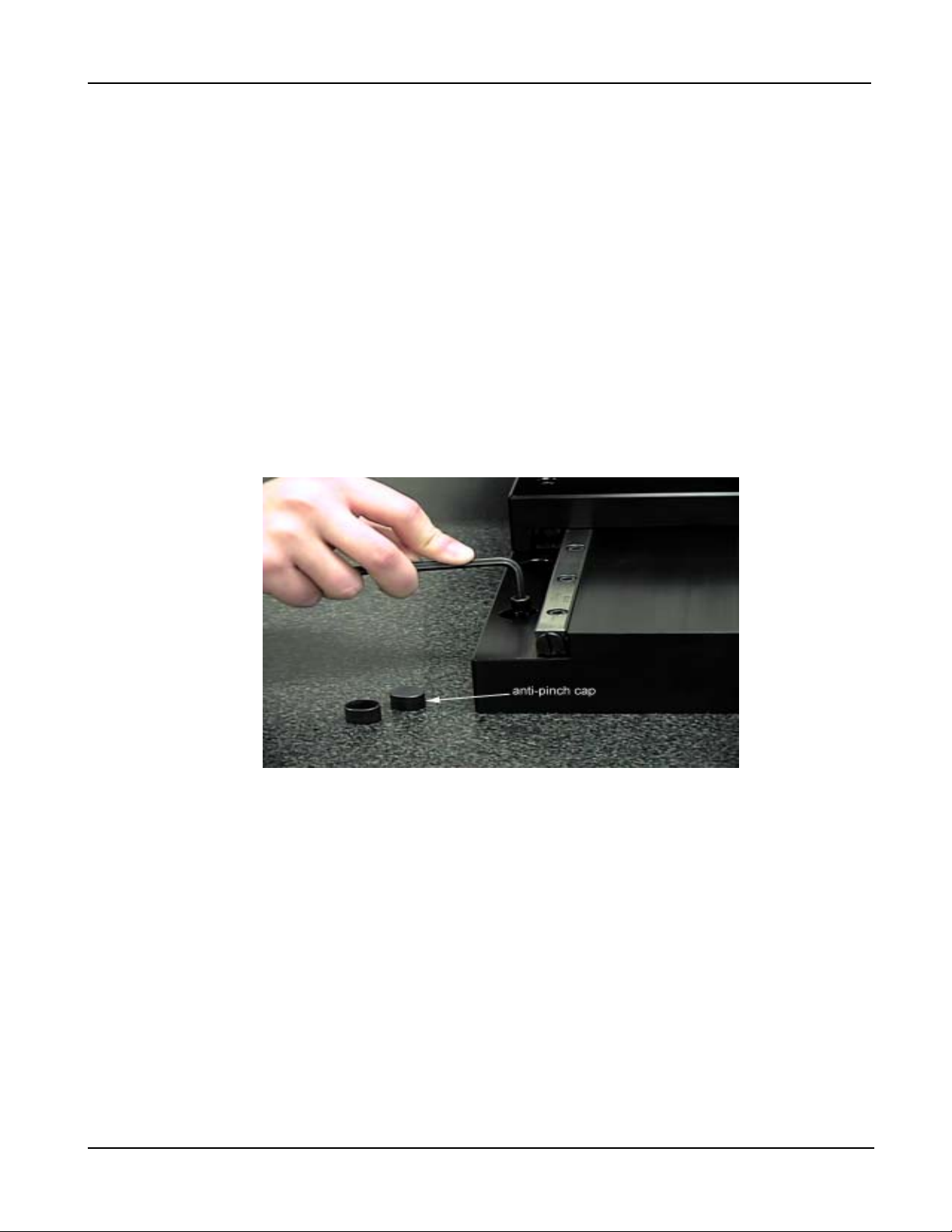
3. After torquing the fasteners, place the supplied anti-pinch caps into the mounting holes.
Ensure that the caps do not protrude above the surface of the bottom stage plate. Use
of these caps is mandatory to ensure CE compliance.
Figure 4
4. Connect the cable from the stage to the motion contoller using the 25 pin interconnect
cable supplied.

9
Newport Corporation TSP Stage Series
Initial Operation
The TSP Stage has been adjusted and calibrated at the factory, prior to shipment. Under normal
circumstances, no calibrations or adjustments are required after the equipment has been set up.
However, it is highly recommended that initial verifications of proper limit switch operation and of
proper configuration of the controller are performed.
Note: If using a controller other than a Newport controller, the stage may not work properly.
Contact Newport technical assistance for modification instructions.
Verification of Proper Limit Switch Operation
The cable needs to be connected and the controller under power to perform this test. When the
controller is referenced below, refer to the manufacturer’s manual for the controller (and control-
ler software, if in use) to find the relevant procedures.
1. Disconnect power to the motor via the controller.
2. Using the manual knob, move the stage to the counterclockwise end-of-travel limit.
3. Check the status of the limit via the controller.
4. If the controller does not indicate arrival at the limit, refer to the Home and Limit
Switches Troubleshooting guide.
5. Repeat steps 3 to 5 for the clockwise end-of-travel limit.

10
Newport Corporation TSP Stage Series
Verification of Proper Controller Configuration
Before using the stage for any application, the controller should be specifically configured and
programmed for operation with the TSP stage. Refer to the manufacturer’s manual for the
controller to find the relevant procedures. Fine tuning of the controller may also be required.
1. Program the controller so that the first move of the stage is a short distance, low velocity
move. The move should be a distance of less than a quarter of full travel at a velocity of
less than 2 mm/sec (.01 in/sec).
2. Perform the first move. Use a suitable indicator to check that the stage has travelled the
required distance.
3. If the stage has not travelled the required distance, refer to the Stage and Controller
Troubleshooting Guide.

11
Newport Corporation TSP Stage Series
Attaching to the Stage
Components’ Surface Flatness
The mating surfaces of components being attached to the stage should be flat to within 2.5um
(0.0001 inch) overall.
Screw Specifications
Use an M6X1 or 1/4-20 screw, depending on whether the mounting holes are metric or english
to attach other components. The length of the screw protruding into the stage should be no
more than 12mm (1/2 inch).
Torque
Components being attached to the stage should be torqued in an alternating pattern. The
maximum torque should not exceed 11.3 N-m (100 in-lbs).
Moment
Components being attached to the stage should not induce a moment of greater than 22.6 N-m
(200 in-lbs).
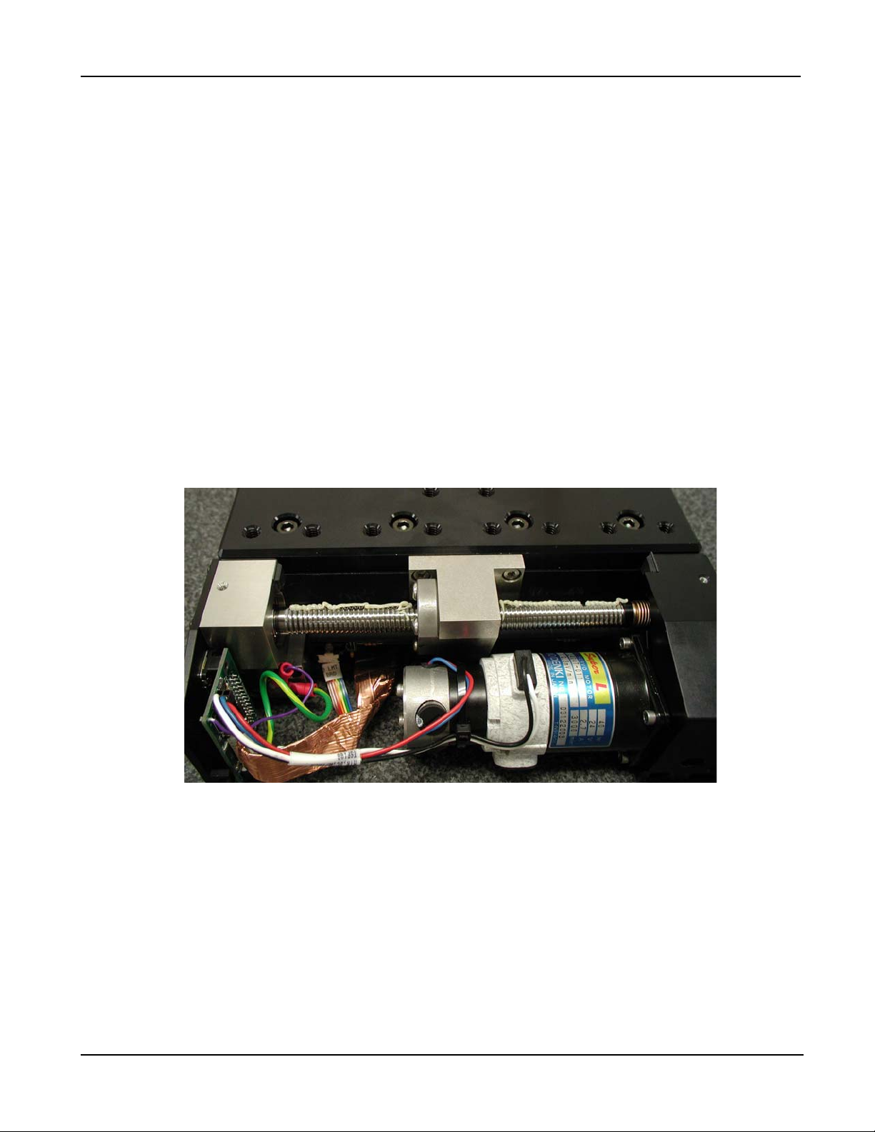
Locations of the connector, end-of-travel (CCW) and (CW), circuit board, home sensor, and ball
screw.
Connector Circuit Board
End Limt
(CW)
Ballscrew
Home Sensor
End Limit
(CCW)
TSP 300 Shown

12
Newport Corporation TSP Stage Series
MAINTENANCE
The frequency of required cleaning, lubrication and testing is highly user dependent. Refer to
Table 2 below to establish a maintenance schedule for your unit.
Table 2

13
Newport Corporation TSP Stage Series
Lubrication
When applying lubricant, do not use either a harsh applicator which may scratch or damage the
stage surfaces, or a fragile applicator, which may generate particles to contaminate the compo-
nent. The recommended lubricant is Lamora® D68 Oil.
Figure 9
14
Newport Corporation TSP Stage Series
1. Inspect the bearing rails for signs of damage or corrosion. Consult Newport’s technical
assistance group if damage or corrosion has occured.
2. Use the manual knob to move the stage to one end-of-travel limit.
3. Clean the exposed bearing rail v-grooves on both upper and lower rails with Isopropyl
alcohol and a lint free cloth.
4. Apply a light film of Lamora® D68 oil to the exposed v-grooves and to the top of the rail
(Figure 9).
5. Move the stage to the other end-of-travel limit and repeat steps 2 and 3.
6. Run the stage from one end-of-travel limit to the other to distribute the lubricant evenly
along the rails.
Ballscrew Lubrication
The recommended lubricant for the ball screw is NBU8 EP grease.
Figure 10
1. Use a 2 mm hex wrench to remove the flat head cap screws from the drive
cover. Remove the drive cover.
2. Inspect the ballscrew for signs of damage or wear.
3. Clean the ballscrew with a lint free cloth, and isopropyl alcohol. Manually move the stage
as required to gain access to all of the ballscrew.

15
Newport Corporation TSP Stage Series
4. Apply light file of the lubricant to the exposed part of the ballscrew (Figure 10).
5. Manually run the stage from one end-of-travel limit to the other to distribute the lubricant
evenly along the ballscrew.
6. Wipe off any access lubricant with a lent free cloth.
7. Replace the drive cover.

16
Newport Corporation TSP Stage Series
17
Newport Corporation TSP Stage Series
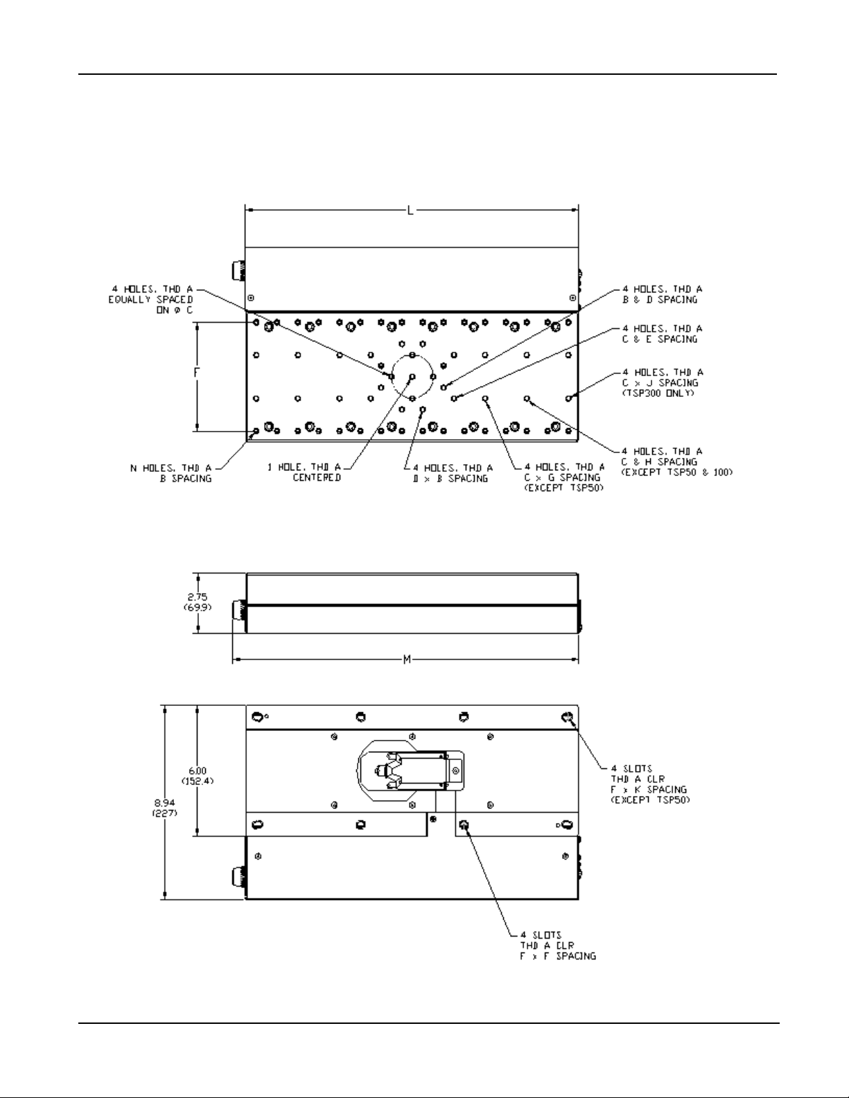
DIMENSIONS
(SEE CHARTS ON NEXT PAGE)

18
Newport Corporation TSP Stage Series
Linear Encoders
Non-Contact Encoder
.1 um Resolution
TTL Quad AB Output (Differential)
4 um Signal Period
Home (Origin) at negative end of travel

19
Newport Corporation TSP Stage Series
STAGE AND CONTROLLER TROUBLESHOOTING GUIDE
provided. The various problems along with the possible causes and corrective actions required are
outlined below.
This section may help you to troubleshoot common problems with operating the equipment
Problem
Stage does not
function
Stage moves a short
distance and stops.
Controller reports
“Following Error” or
other motion error.
Stage motion un-
steady or jerky
Stage travels less
than specifications
Stage does not meet
specifications
Tighten connector.
Check that cables are correctly connected
and wired.
Refer to the manufacturer’s manual for the
controller
Refer to the manufacturer’s manual for the
controller
Check for and remove all obstructions
Tighten coupling
Tighten connector
Motor plus/minus leads reversed and/or
tachometer plus/minus leads reversed
Contact Newport for assistance
Lower velocity and/or acceleration
Check for and remove all obstructions. Clean
rails according to the procedures outlined in
this manual
Tighten connectors. Check cabling and
replace or repair as necessary
Contact Newport for assistance
Refer to the manufacturer’s manual for the
controller
Check for and remove all obstructions
Ensure that all cables are clear of the moving
equipment
If roller creep is suspected, contact Newport
for assistance
Refer to Setup, Environmental consider-
ations in this manual
Refer to Setup, Environmental consider-
ations in this manual
Refer to the specifications in this manual and
consult Newport for assistance
Contact Newport for assistance
Consult Newport for recalibration or certifica-
tion
Loose connector at stage
Stage incorrectly connected to control-
ler
Controller incorrectly programmed.
Limits not enabled via software
Controller not connected to power
source
Obstruction to movement
Loose motor coupling
Loose connectors at stage or controller
Incorrectly wired cabling
Stage incorrectly tuned
Load too large for motion profile used
Obstrucion or foreign object on bearing
rails
Loose connections or faulty cabling
Stage incorrectly tuned
Controller incorrectly programmed
Obstruction to motion
Entangled cables
Roller creep
Improper mounting
Improper attachment
Stage outside of environmental specifi-
cations
Stage incorrectly tuned
Improper handling and/or transport
Cause Corrective Action

20
Newport Corporation TSP Stage Series
Stage makes un-
usual noise
Controller reports
that both end limits
are active
Object contacting the manual operation
knob
Loose covers
Entangled cables
Stage incorrectly tuned
Loose connector
Faulty or miswired cables
Controller incorrectly programmed
Remove object
Tighten screws
Ensure that all cables are clear of the mov-
ing equipment
Contact Newport for assistance
Tighten all connectors
Check cabling and rewire or repair as neces-
sary
Refer to the manufacturer’s manual for the
controller
Problem Cause Corrective Action
This manual suits for next models
5
Table of contents
Other Newport Industrial Equipment manuals

Newport
Newport PM 500 Installation manual

Newport
Newport GTS-V Series User manual

Newport
Newport GTS30V User manual

Newport
Newport New Focus 8892 User manual

Newport
Newport UTM Series User manual

Newport
Newport FMS Series User manual

Newport
Newport ORIEL Instruments Cornerstone 260 User manual

Newport
Newport IDL165-LM Series User manual

Newport
Newport RV User manual


