Micronix PR-32 Series User manual

S e r i e s
Reference Manual
Piezo Rotation Stage
(Open and Closed Loop Versions)
PR-32

MICRONIX USA, LLC
Tel: 949-480-0538
Fax: 949-480-0538
Email: [email protected]
http://micronixusa.com
PR-32
Piezo Rotation Stage
Reference Manual
Rev 3.06

PR-32 Piezo Rotation Stage
1
MICRONIX USA,LLC
www.micronixusa.com
Rev: 3.06
Reference Manual
Contents
1. Introduction ...............................................................................................................................................3
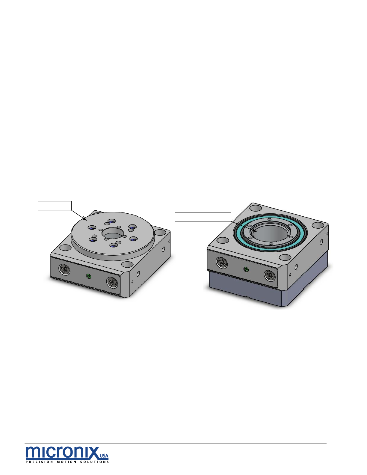
1.1 Product Description ...............................................................................................................................3
1.2 Recommended Controllers ..................................................................................................................4
1.3 Technical Data .......................................................................................................................................4
1.4 Load Characteristics..............................................................................................................................4
2. Model Configurations ...............................................................................................................................5
2.1 PR-32 Order Numbers.............................................................................................................................5
3. Preparing to Install the PR-32 ...................................................................................................................6
3.1 Installation Preparation..........................................................................................................................6
3.2 Package Contents .................................................................................................................................6
4. Installing the PR-32....................................................................................................................................6
4.1 PR-32 Installation.....................................................................................................................................7
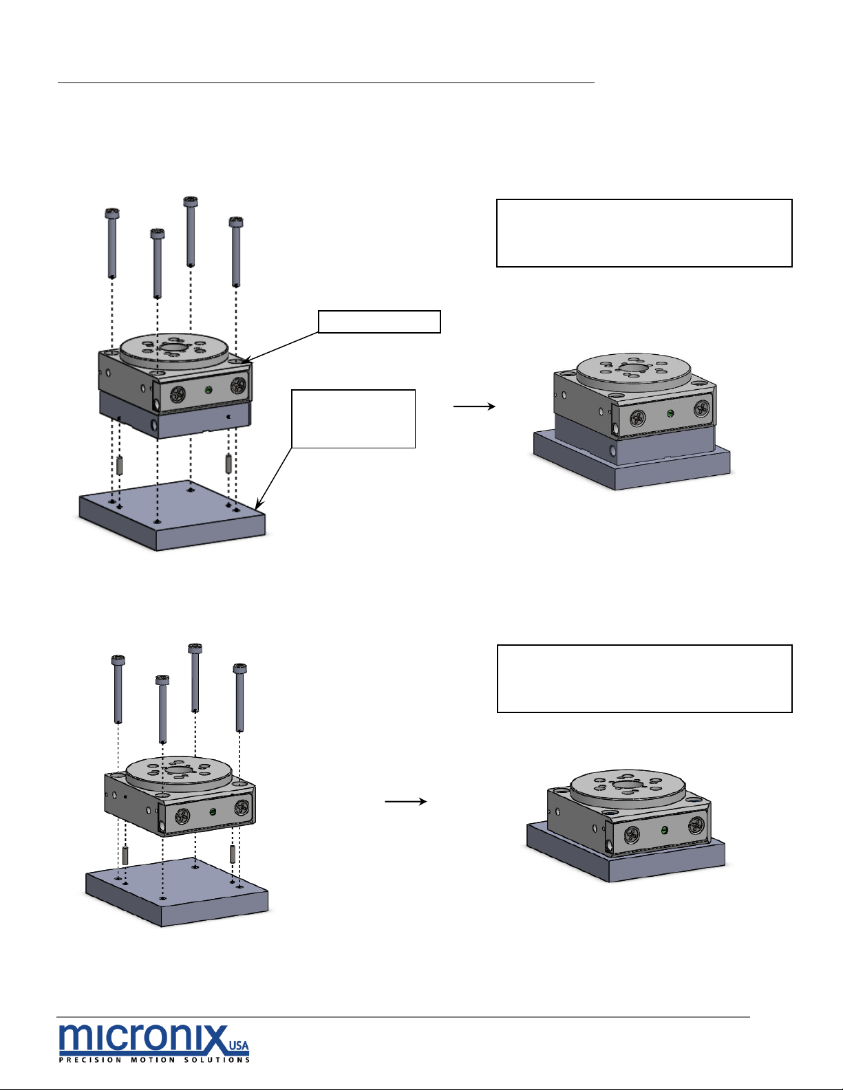
4.1.1 General Mounting...........................................................................................................................7
5. Connecting the PR-32...............................................................................................................................8
5.1 Atmospheric Environments ...................................................................................................................8
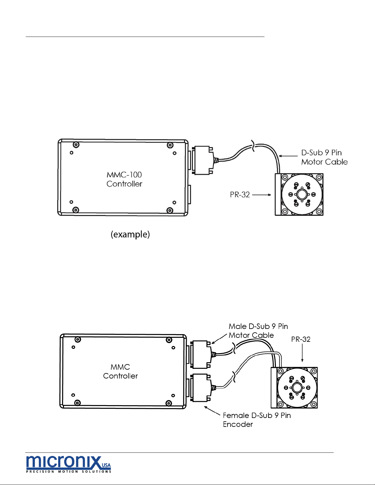
5.1.1 Open Loop Installation & Wiring Diagram...................................................................................8
5.1.2 Closed Loop/Encoder Installation & Wiring Diagram ................................................................8
5.1.3 Wiring Diagram for Atmospheric System with Analog Encoder ...............................................8
5.2 Vacuum Environments...........................................................................................................................9
5.2.1 Handling and Preparation .............................................................................................................9
5.2.2 Open loop Installation & Wiring Diagram....................................................................................9
5.2.3 Closed Loop/Encoder Installation & Wiring Diagram ................................................................9
6. Technical Specifications ........................................................................................................................10
6.1 Dimensions.............................................................................................................................................10
7. Stacking Configurations .........................................................................................................................11
7.1 Configuration Examples (Additional configurations available upon request)............................11
8. Supplementary Information ...................................................................................................................11
8.1 Units and Conventions.........................................................................................................................11
8.2 Maintenance ........................................................................................................................................11
A. Appendix.................................................................................................................................................12
A.1 Electrical Connections.........................................................................................................................12
A.1.1 DB-9 Male Motor Connector .......................................................................................................12
A.1.2 Encoder Pinout ..............................................................................................................................12
A.2 Phase Piezo Motor Wiring Diagram....................................................................................................12
A.3 Open Loop Vacuum Wiring Diagram ...............................................................................................13
A.3.1 Straight Through 9-Pin Feed Through..........................................................................................13

PR-32 Piezo Rotation Stage
2
MICRONIX USA,LLC
www.micronixusa.com
Rev: 3.06
Reference Manual
A.4 Using an Analog Encoder ...................................................................................................................14
A.4.1 Analog Encoder Overview ..........................................................................................................14
A.4.2 Operating and Electrical Specifications....................................................................................14
A.4.3 Analog Output (Pins 1,2,6, and 7)...............................................................................................14
A.4.4 Index Window (Pins 3)...................................................................................................................14
A.4.5 Resolution .......................................................................................................................................15
A.4.6 Analog Encoder Wiring Diagram................................................................................................15
A.4.7 Straight Through 15-Pin Feed Through........................................................................................15

PR-32 Piezo Rotation Stage
3
MICRONIX USA,LLC
www.micronixusa.com
Rev: 3.06
Reference Manual
1. Introduction
1.1 Product Description
The PR-32 is a compact rotation stage with unlimited travel. The use of two mutually
pre-loaded steel ball bearings guarantees smooth motion and high stability. It
utilizes our patent-pending multi-phase piezo motor resulting in high speed (> 30
°/s) and high blocking torque. The PR-32 can be combined with the linear PPX-32
or with the PPS-series stages. Vacuum and Ultra High Vacuum (10-9 mbar)
compatible versions are available.
Features:
▪360° continuous
▪Load capacity up to 1kg
▪10 µ°encoder resolution
▪.5” Clear aperture (open loop)
Carriage
.5” Aperture

PR-32 Piezo Rotation Stage
4
MICRONIX USA,LLC
www.micronixusa.com
Rev: 3.06
Reference Manual
1.2 Recommended Controllers
The following controllers are available from MICRONIX USA:
▪MMC-100
▪MMC-110
1.3 Technical Data
Motor
PM-002R
Speed Max. (°/sec)
6 (MMC-100), 30 (MMC-110)
Resolution Typical (µ°)
3.6 (open loop), 50 (Analog Encoder), 10
(Digital Encoder)
Bi-directional Repeatability (µ°)
N/A (open loop), ± 200 (Analog
Encoder), 200 (Digital Encoder)
Uni-directional Repeatability (µ°)
N/A (open loop), 200(Analog Encoder),
200 (Digital Encoder)
1.4 Load Characteristics
Load Characteristics
Fr(N)
FZ(N)
Mr(Nm)
MZ(Nm)
kar(µrad/Nm)
PM-002R
10
10
0.5
0.025
-

PR-32 Piezo Rotation Stage
5
MICRONIX USA,LLC
www.micronixusa.com
Rev: 3.06
Reference Manual
2. Model Configurations
2.1 PR-32 Order Numbers
Contact MICRONIX USA for custom versions and stacking configurations.
Order No. PR-32-
1
1
Piezo Motor, PM-002R 1
360° Continuous 1
None 0
Analog (1Vpp) 2
Digital (RS-422) 3
None 0
Magnetic 1
Atmospheric 0
High Vacuum, 10-6 mbar 6
Ultra-High Vacuum, 10-9 mbar 9

PR-32 Piezo Rotation Stage
6
MICRONIX USA,LLC
www.micronixusa.com
Rev: 3.06
Reference Manual
3. Preparing to Install the PR-32
3.1 Installation Preparation
When mounting the stage, it is important to consider the flatness of the mounting
surface, as the stage will conform to the shape of that mounting surface. A surface
that is not flat can adversely affect the performance and structural integrity of the
stage.
The stage is calibrated and guaranteed to be within specification at 20°C ±5°C.
Be sure to use the stage under the following conditions:
▪Mount to a clean and flat surface which is free of debris, burrs or dings
▪An indoor atmosphere free of corrosive gasses, and condensation
▪Temperature range of 0-40°C
▪Relative humidity between 20-80%
▪Locate away from water, heat, and electrical noise
3.2 Package Contents
If the product is damaged or there are missing components, contact MICRONIX
USA immediately. Do not discard product packaging in case of return shipment.
Package Should Contain:
▪PR-32 Rotary Stage
▪Reference Manual
▪Any other previously agreed upon components such as a controller
4. Installing the PR-32
All mounting patterns require M2 screws for mounting and M1.5 x 5mm dowel pins
for precision alignment. Additional brackets and screws may be needed for
custom applications.
Top View
Stage Mounting Pattern

PR-32 Piezo Rotation Stage
7
MICRONIX USA,LLC
www.micronixusa.com
Rev: 3.06
Reference Manual
4.1 PR-32 Installation
4.1.1 General Mounting
For general mounting configurations, mount the base to the mounting surface.
Closed Loop System Requires:
2x M1.5 x 5mm Dowel Pins
4x M2 x 25mm Cheese Head Cap Screws
1. Install Dowel Pins and M2
Socket Head Cap Screws
Customer Supplied
Base Plate or
Mounting Surface
Clearance Hole x4
Open Loop System Requires:
2x M1.5 x 5mm Dowel Pins
4x M2 x 12mm Cheese Head Cap Screws
1. Install Dowel Pins and M2
Socket Head Cap Screw
2. Tighten 4x Mounting Screws

PR-32 Piezo Rotation Stage
8
MICRONIX USA,LLC
www.micronixusa.com
Rev: 3.06
Reference Manual
5. Connecting the PR-32
5.1 Atmospheric Environments
For controller information refer to the appropriate MMC controller manual.
5.1.1 Open Loop Installation & Wiring Diagram
Connecting the PR-32 in an open loop configuration only requires that the D-sub
9 Pin Motor Cable be connected to a compatible controller. No other cables or
components are needed.
5.1.2 Closed Loop/Encoder Installation & Wiring Diagram
Using the PR-32 stage with an encoder requires a closed loop compatible
controller that recognizes encoder feedback.
5.1.3 Wiring Diagram for Atmospheric System with Analog Encoder

PR-32 Piezo Rotation Stage
9
MICRONIX USA,LLC
www.micronixusa.com
Rev: 3.06
Reference Manual
5.2 Vacuum Environments
5.2.1 Handling and Preparation
When preparing the stage for vacuum environments, take the necessary
precautions (wearing latex gloves, clean room clothing, etc.) when handling the
stage to avoid any contaminants. Maximum Bake-out temperature 100° C.
MICRONIX USA supplies the stage with vacuum compatible connectors: 9-pin
female PEEK connector for open loop, 15-Pin female PEEK connector for closed
loop.
5.2.2 Open loop Installation & Wiring Diagram
Connecting an open loop PR-32 in a vacuum chamber requires the use of a feed
through connector at the vacuum chamber wall. The vacuum compatible PR-32
will be supplied with wiring for a straight through feed through not a cross over
gender changer. MICRONIX USA supplies test connectors that simulate the
vacuum feed through to allow functionality test prior to installation in a vacuum
chamber. For details regarding the pin-out and feed through specifications see
the Appendix A.3.
5.2.3 Closed Loop/Encoder Installation & Wiring Diagram
Closed loop installation of the PR-32 stage in vacuum environments requires the
use of a feed through connector at the vacuum chamber wall. The vacuum
compatible PR-32 will be supplied with wiring for a straight through feed through
not a cross over gender changer. MICRONIX USA supplies test connectors that
simulate the vacuum feed through to allow functionality test prior to installation in
a vacuum chamber. For details regarding the pin-out and feed through
specifications see the Appendix A.4.

PR-32 Piezo Rotation Stage
10
MICRONIX USA,LLC
www.micronixusa.com
Rev: 3.06
Reference Manual
5.2.3.1 Wiring Diagram for System with Analog Encoder
6. Technical Specifications
6.1 Dimensions

PR-32 Piezo Rotation Stage
11
MICRONIX USA,LLC
www.micronixusa.com
Rev: 3.06
Reference Manual
Stacking Configurations
7.1 Configuration Examples (Additional configurations available upon request)
8Supplementary Information
8.1 Units and Conventions
All measurements in this document are in the metric system of units.
Metric Unit
English Unit
1 millimeter
0.0394 inches
1 micron
0.0000394 inches
1 Newton
0.2248 lbs.
1 Newton-meter
8.85 in-lbs.
8.2 Maintenance
▪The PR-32 series of rotary stages utilizes a maintenance free design. Do not
modify the stage or perform any maintenance unless specifically instructed
to do so by MICRONIX USA personal. If the stage is not performing up to the
original specifications, please contact MICRONIX USA.
▪The PR-32 rotary stage is a precision mechanical device and
should be handled with care. Do not drop or mishandle the
stage.
▪Do not touch the bearings, as this will contaminate the lubrication and
jeopardize the longevity of the stage.
▪Follow the Installation Preparation requirements and use proper cable
management to ensure a clean and safe operating environment.
Using Adapter Plate (P/N: 430517)
PPS-28 & PR-32
PPX-32CR & PR-32

PR-32 Piezo Rotation Stage
12
MICRONIX USA,LLC
www.micronixusa.com
Rev: 3.06
Reference Manual
A.Appendix
A.1 Electrical Connections
A.1.1 DB-9 Male Motor Connector
A.1.2 Encoder Pinout
A.2 Phase Piezo Motor Wiring Diagram
Pin
Description
Color
1
Phase 1
Red
2
Phase 2
Yellow
3
N/C
N/C
4
Not in Use
N/C
5
Ground
Black& Green
6
+5V
N/C
7
+5V
N/C
8
Not in Use
N/C
9
Not in Use
N/C
Pin
Function
Analog
1
A+/Cos+
Brown
2
B+/Sin+
Yellow
3
Index+
Violet
4
GND
Black & Inside shield
5
+5V
Red
6
A-/Cos-
Orange
7
B-/Sin-
Green
8
Index-
Blue
9
N/A
N/A
Shield
GND
Outside Shield

PR-32 Piezo Rotation Stage
13
MICRONIX USA,LLC
www.micronixusa.com
Rev: 3.06
Reference Manual
A.3 Open Loop Vacuum Wiring Diagram
A.3.1 Straight Through 9-Pin Feed Through

PR-32 Piezo Rotation Stage
14
MICRONIX USA,LLC
www.micronixusa.com
Rev: 3.06
Reference Manual
A.4 Using an Analog Encoder
A.4.1 Analog Encoder Overview
A PR-32 with Analog encoder will need to be paired with an appropriate controller. The
MMC-100 has an Analog option. The PR-32 with an analog encoder will be supplied with
a 15-pin connector that incorporates both motor and encoder signals.
A.4.2 Operating and Electrical Specifications
A.4.3 Analog Output (Pins 1,2,6, and 7)
A.4.4 Index Window (Pins 3)
Power Supply
5VDC ±5% @ 330mA (60mA for sensor)
Operating Temperature
0 to 70°C
Humidity
10 - 90% RH non-condensing

PR-32 Piezo Rotation Stage
15
MICRONIX USA,LLC
www.micronixusa.com
Rev: 3.06
Reference Manual
A.4.5 Resolution
Interpolation done in controller to a higher resolution as specified in the
order. With an analog encoder the MMC-110 has an achievable
Resolution down to 10μ°.
A.4.6 Analog Encoder Wiring Diagram
A.4.7 Straight Through 15-Pin Feed Through
AC
D
B
J1 J2 J3 J4
J6J5
Standard Cable Descriptions:
A. PR-32 Motor Cable - Vacuum Side (Female Dsub 15 Pin, 1.5m)
B. PR-32 Encoder Cable - Vacuum Side (Female Dsub 15 Pin, 1.5m)
C. Atmospheric Encoder Cable (Female Dsub 15 Pin to Female Dsub 9 Pin, 1.5m)
D. Atmospheric Motor Cable (Female Dsub 15 Pin to Male Dsub 9 Pin, 1.5m)
Description: Color J1 J2 J3 J4 J5 J6
Phase 1 Red 1 1 8 8 (Red) 1
Phase 2 Yellow 2 2 7 7 (White - Green TP) 2
Ground Black/Green 9 9 15 15 (Black&Green) 5
Shield - 10 10 14 14 (Shield) Casing
GND Black 8 8 1 1 (Black) 4
Cos+ Brown 7 7 2 2 (Brown) 1
+5V Red 6 6 3 3 (Red) 5
Cos- Orange 5 5 4 4 (White - Brown TP) 6
Sin+ Yellow 4 4 5 5 (Yellow) 2
Sin- Green 12 12 12 12 (White - Yellow TP) 7
Index- Blue 13 13 11 11 (White - Violet TP) 8
Index+ Violet 14 14 10 10 (Violet) 3
Shield - 15 15 9 9 (Shield) Casing
Female PEEK Dsub15 Connector - Rear View
87654
151413121110
321
Wiring Diagram:
Female Dsub9 Connector - Rear View
54321
9876
Male Dsub9 Connector - Rear View
12345
6789
Table of contents
Other Micronix Industrial Equipment manuals
Popular Industrial Equipment manuals by other brands

Metso
Metso Nordtrack J90 instructions

ASCO Numatics
ASCO Numatics 453 Installation and maintenance instructions

probst
probst TSV operating instructions

IEMCA
IEMCA MASTER 880-E P/F Manual for use and maintenance

Siemens
Siemens WBMMFM installation instructions

Eaton
Eaton NZM1-XDTV Series Instruction leaflet

AIR2G2
AIR2G2 AIR2G2-336 Owner's/operator's manual

Mirion Technologies
Mirion Technologies CheckPoint:Gate RTM690 Technical handbook

SCHUNK
SCHUNK WSG 25 Assembly and operating manual

Lemmer
Lemmer HVLP T Series owner's manual

GEA
GEA OSD 35-0136-067 Instruction manual and parts list

Winterthur Gas & Diesel Ltd.
Winterthur Gas & Diesel Ltd. X52 Operation manual