Microsensor MFE600C User manual

MFE600C
Operation Manual
V1.0

I
Contents
1 Introduction.......................................................................................................................................... 1
2 Specifications...................................................................................................................................... 1
3 Electrical Connection.......................................................................................................................... 2
3.1 Integrated wiring .......................................................................................................................... 2
3.2 Separated wiring.......................................................................................................................... 3
4 Start up................................................................................................................................................ 4
5 Operation............................................................................................................................................. 6
5.1 Key instruction ............................................................................................................................. 6
5.2 Key operation............................................................................................................................... 7
6 Parameter setting and method............................................................................................................ 7
6.1 Report query................................................................................................................................ 7
6.2 Parameters setting....................................................................................................................... 7
6.3 Level 1 password menu............................................................................................................... 8
6.4 Level 2 menu ............................................................................................................................... 9
7 Installation......................................................................................................................................... 13
8 Modbus RTU communication............................................................................................................ 15
9 Responsibility.................................................................................................................................... 20
Our company reserves the right to modify this manual due to product technology and process updates. If
there are changes, no further notice will be given.
Please note the latest version of this manual.
The company reserves the right of final interpretation of this manual.
1
Thank you very much for choosing our products. In order to better use the product, it is recommended
that you read the instructions carefully before using the product.
1 Introduction
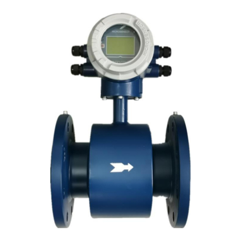
MFE600C Insert electromagnetic flowmeter (hereinafter referred to as plug-in flowmeter is designed and
manufactured with the most advanced domestic and abroad technology. It has the characteristics of high
reliability, good stability, and long service life.
The plug-in electromagnetic flowmeter is a new type of flow measurement instrument developed on the
basis of the pipeline electromagnetic flowmeter. On the basis of retaining the advantages of the pipeline
electromagnetic flowmeter, it avoids the disadvantages of difficult and expensive installation of the
pipeline electromagnetic flowmeter on a large pipeline. In particular, the method of tapping under
pressure and installation under pressure can be adopted, so that the plug-in flowmeter can be
constructed and installed without stopping the water. It provides a new method for liquid flow
measurement and installation. It has been widely used in chemical, water supply and drainage, sewage
treatment and other industries.
2 Specifications
Table1
Diameter
DN150~DN1600
Measurement accuracy
±2.5%
Electrode type
Standard fixed electrode
Pressure port
ANSI 1/2 NPT, JIS G1/2
Structure type
Integrated type, separated type (cable length of separated type≤100m)
Rated pressure
0.6Mpa, 1.0Mpa, 1.6Mpa
Electrode material
316L, Ti
Ball valve material
Stainless steel
Probe
ABS
Flange/body flange
Stainless steel
Converter housing
Aluminum die-casting
Power supply
100 V AC~240V AC
12V DC,24V DC
Battery supply (LCD display, RS485 output, wireless output, frequency/pulse output, and the
frequency/pulse output is used only for calibration purposes.)
Output signal
4mA~20mA DC (load resistance 0Ω~750Ω, active output)
Hart
Frequency, pulse output (Passive, active output optional)
Upper and lower limit alarm output
RS485(Modbus protocol), RS232
Profibus-DP, Profibus-PA
4G wireless transmission
Electrical connection
ISO M20×1.5

2
IP protection
IP65, IP68: submersible, long-term working in water, suitable for instrument installation in
instrument well.
Environmental temp.
Working temp.: -20℃~60℃
Storage temp.
-40℃~60℃
Relative humidity
5%~90%
3 Electrical Connection
The Insert electromagnetic flowmeter converter can be divided into integrated converter and separated
converter, and the wiring diagram is shown in Figure 1 and Figure 2.
When wiring, please note:
a) RS485 communication cable needs to use two-core twisted pair shielded wire;
b) The same cable shall not be used for the power line and 4mA~20mA DC signal line. Two cables
shall be connected separately.
3.1 Integrated wiring
1
2
3
4
5
6
7
8
9
10
11
12
13
14
1
15
T-/B
RS232
T+/A
IOUT
POUT
COM
AH
AL
+3.3V
S1
S0
1
S2
GND
COM
+24V
+IN
0V
1
2
Current
Passive
Active
Pulse
Passive
Active
RS232
1
3
RS485
RS485 RS232
1
2
4-20mA
Pulse
modbus
22
21
20
19
18
220V
220V
PE
-24V
+24V
EX2
EX1
1617
Figure 1 Integrated wiring diagram
When wiring, select the corresponding power terminal to connect to the power line according to the
product specifications, and then connect to the signal line according to the required output signal. See
Table 2 for the specific meaning of the integrated electromagnetic flowmeter wiring terminals.
Table 2
Terminal Symbol
Function
1
T-/B
RS485/RS232 communication output
2
RS232 GND
RS232 grounding wire
3
T+/A
RS485/RS232 communication input
4
IOUT
4mA~20mA DC output;

3
5
+24V DC COM
4mA~20mA DC output grounding wire;
6
POUT
Pulse/frequency output
7
COM
Pulse/frequency output grounding wire
8
AH
Alarm output for Upper Limit of flow
9
AL
Alarm output for Lower Limit of flow
10
+3.3V
Pressure transmitter +IN
11
+IN
Pressure transmitter output terminal
12
0V
Pressure transmitter GND
13
S1
Electrode wire
14
S0
Signal grounding wire
15
S2
Electrode wire
20
PE
Power grounding wire
21
220V
220V AC power supply access
22
220V
19
-24V
24V DC (12V DC) power supply access
18
+24V
16
EX1
Exciting current
17
EX2
Short
Circuit
lugs
Passive
When lugs are connected to Passive, the current①or pulse
②will output an active signal.
Active
When lugs are connected to Active, the current①or pulse②
will output a passive signal.
3.2 Separated wiring
220V
220V
PE
24V
24V
12 3 4 5 6 7 8 910 11 12 16 17 18
T-/A
RS232
T+/B
I.mA
P+
PCOM
ALMH
ALML
+3.3V
S1
S0
S2
GND
ICOM
+24V
+IN 0V
13 14
EX1
EX2
DS1
DS2
interface
Pressure
network
Shielded
network
Shielded
4-20mA
Passive
Active
1
Pulse
2
Active
Passive
Figure 2 Separated wiring diagram
When wiring, select the corresponding power terminal to connect to the power line
according to the product specifications, and then connect to the signal line according to the
required output form. See Table 3 for the specific meaning of the integrated electromagnetic
flowmeter wiring terminals.
Table 3

4
4 Start up
4.1 Switch on
Before turning on the power, please check that the system has been properly installed as required,
including:
a) The instrument shall be mechanically safe and shall be installed in accordance with regulations;
b) The power supply shall be connected according to regulations;
c) The electrical connection wire of the cavity shall be protected, and the cap shall be tightened;
Terminal Symbol
Function
1
T-/A
RS485/RS232 communication output
2
RS232 GND
RS232 grounding wire
3
T+/B
RS485/RS232 communication input
4
I.mA
4mA~20mA DC output;
5
Icom +24V
Current output grounding wire
6
P+
2-way flow pulse output/frequency output
7
Pcom
Pulse output grounding wire
8
ALMH
Alarm output for Upper Limit of flow
9
ALML
Alarm output for Lower Limit of flow
10
+3.3V
Pressure transmitter +IN
11
+IN
Pressure transmitter output terminal
12
0V
Pressure transmitter GND
13
EX1
Exciting current
14
EX2
Shielding network
DS1
16
S1
Electrode wire
17
S0
Signal grounding wire
18
S2
Electrode wire
Shielding network
DS2
220V
220V
220V AC power supply access
220V
220V
24V
24V
24V DC power supply access
24V
24V
Short Circuit lugs
Passive
When lugs are connected to Passive, the current①or pulse②will
output an active signal.
Active
When lugs are connected to Active, the current①or pulse②will
output a passive signal.

5
d) Please check whether the running data of the power supply is correct.
4.2 Converter start-up
The measuring instrument is composed of a sensor and a converter and is ready for immediate use
when it is supplied. All operating data is factory set according to your order, please refer to the provided
inspection report for details.
After turning on the power, the flowmeter performs a self-check first. After the self-check, the flow meter
directly starts flow measurement and displays the current measured value.
Figure 3 Main interface of flow meter
The detailed information of the flowmeter interface status after startup is shown in Table 4.
Table 4
Display
Description
Reuse content
①
Real-time flow value and unit
Null
②
Real-time flow rate and unit
Click down key to switch display: %, resistance value
③
Alarm mark
System alarm, you can check the alarm content by up key
④
Cumulative flow and unit
Positive cumulant, negative cumulant, cumulant algebraic sum, and
check the specific alarm content by up key
The "bell" sign at the upper right of the meter is an alarm sign. You can view the alarm message by the
key. The possible causes for the alarm are shown in Table 5.
Table 5
Item
Alarm content
Possible causes
1
Excitation
impassability
The excitation part is not working normally. The excitation line may be loose or
misconnected
2
Empty pipe
The fluid is not filled with pipe; the media conductivity is less than 5us; the electrode is
misconnected

6
3
Electrode
The fluid is not filled with pipe; the media conductivity is less than 5us; the electrode is
misconnected
4
Upper flow limit
The real-time flow value is higher than the set upper limit of alarm value
5
Lower flow limit
The real-time flow value is lower than the set lower limit of alarm value
5 Operation
5.1 Key instruction
The electromagnetic flowmeter display and operation interface are shown in Figure 4. There is a key on
the left side of the screen and 4 keys on the bottom side of the display screen.
Figure 4 Operation interface
The meaning of the keys and operation methods are shown in Table 6. The composite key needs to
press two keys at the same time. If there is no key operation within 10 minutes, it will automatically return
to the main screen. This version does not provide touch keys or infrared remote-control keys. If you need
to set up, you must open the front cover.
Table 6
Key
Sign
Function
Shift
1. Use in combination with the confirm key to enter the
password interface;
2. Cursor movement during password input
Down
Number minus 1 or page down
Up
Number plus 1 or page up
Enter
Enter or exit

7
Function
Enter key for report, data reset and other functions
5.2 Key operation
The meter can enter the menu setting interface by simultaneously pressing the "shift" and "enter".
Customers can choose the corresponding password to enter the menu for operation according to
different needs. The meter password has two levels: level 1 password is 19818 and the level 2 password
is 29818. The authority of level 1 password is different from that of level 2 password. Level 2 password
has higher authority and more parameters can be changed. If customers need to modify level 1 or 2
password, it can be done in the secondary menu password modification item.
Note: If you modify level 1 or level 2 password, please remember the modified password!
6 Parameter setting and method
6.1 Report query
In the main interface state (Figure 4), press (Function key) to enter the report query interface
(Figure 5), and then select the corresponding function to view the data according to actual needs.
Figure 5 Report query interface
Users can query 4 types of reports: daily, monthly, annual, and power outage reports. The meter can
save up to 90 daily reports, 36 monthly reports, 3 annual reports and 20 power outage reports.
6.2 Parameters setting
In the main interface state (Figure 4), press + ("shift" + "enter”) to enter the password input
interface (Figure 6). The user enters the corresponding password by entering different levels of
passwords. The menu sets the parameters related to the use of the flowmeter.
Special tips: Please operate carefully when setting, so as to avoid the failure of the flowmeter due to the
parameter setting!
Figure 6 Password input interface
Day Report
Month Report
Year Report
Power Report
Pass Word Input
00000

8
6.3 Level 1 password menu
Users enter the menu through level 1 password "19818” and can set the parameters in the menu. The
specific parameter information and data type are shown in Table 6.
Table 6
Items
Functions
Setting/Instructions
Parameter Range
1
Communication
address
Range:0~255
2
Communication
rate
Rate:1200,2400,4800,9600,14400
Check: no check, odd parity Check, even
parity check
3
Range setting
m³/h,L/s,L/m,L/h,Ukg/s,Ukg/m,Ukg/h,Usg/s,U
sg/m,Usg/h,T/s,T/m,T/h,kg/s,kg/m,kg/h,m³/s,
m³/m
4
Damping time
0.5S,0.8S,1.0S,2S,3S,4S,5S,6S,8S,10S,20S
,30S,50S,100S
5
Zero velocity
correction
6
Small signal
excision
Data type: integer
Range:0~100%
7
Remove display
Yes, NO
COM Baud Rate
9600 N
Low Cutoff Mode
Disable
Low Flow Cutoff
0.50 %
Zero Correct Set
V= +0.000m/s
Zero:+0.000m/s
Damp Time Set
1 s
Flow Range Max
282.7439 m³/h
COM Address
001 k

9
8
Flow direction
Positive, reverse
9
Reverse
measurement
Yes, No
10
Empty pipe
alarm
Yes, No
11
Empty pipe
alarm threshold
value
As customers’ request
12
Flow integration
unit
1m³,0.1m³,0.01m³,0.001m³,1L,0.1L,0.01L,0.0
01L,1t,0.1t,0.01t,0.001t,1kg,0.1kg,0.01kg,0.0
01kg,1gal,0.1gal,0.01gal,0.001gal,1ig,0.1ig,0
.01ig,0.001ig,
13
Pulse output
method
Frequency output, pulse output
14
Frequency
output range
1~5000
15
LCD screen
brightness
1~5 adjustable
6.4 Level 2 menu
Users enter the menu through level 2 password "29818” and can set the parameters in the menu. The
LCD Brightness
Frequency Range
1000 HZ
Pulse Output Mode
Frequency
Unit Totalizer
0.001 m³
Empty Threshold
100.0 KΩ
Detect Empty Pipe
Enable
Reverse Measure
Enable
Flow Direction
Forward

10
specific parameter information and data type are shown in Table 7.
Table 7
Items
Functions
Setting/Instructions
Parameter Range
1
Upper limit
alarm
Yes, No
2
Upper limit
alarm value
Full scale percentage setting
3
Lower limit
alarm
Yes, No
4
Lower limit
alarm value
Full scale percentage setting
5
Current zero
point
correction
adjustable
6
Current
full-scale
correction
adjustable
7
Excitation
method
4 types: 50 Hz,25 Hz,12.5 Hz,6.25 Hz
8
Excitation
current test
Excite Test
Disable
Excite Mode
Mode 4
Current Full Adj.
0.9960
Current Zero Adj.
0.9917
Lower Threshold
20.00 %
Lower Limit Alarm
Disable
Upper Threshold
80.00 %
Upper Limit Alarm
Disable

11
9
Current output
0mA~10mA,4mA~20mA
10
Output test
20mA/2000Hz,10mA/1000Hz,4.16mA/
20Hz,4mA/1Hz
11
Density of
measured
fluid
As customers’ request
12
Change rate
limit value
0~100% adjustable
13
Insensitive
time
0~99S adjustable
14
Acquisition
buffer depth
0~199 adjustable
15
Pressure
sensor full
scale
0.6MPa,1.0MPa,1.6MPa
16
Sensor
coefficient
value
Factory set, unchangeable
17
Additional
coefficient
Factory set, unchangeable
Additional Factor
1.0000
Sensor Factor
1.0000
Press Range Max
0.6000 MPa
Buffer Size
004
Slope Limit Time
10 s
Slope Limit
30.0 %
Liquid Density
1.000 t/m³
Output Test
Disable
Current Mode
4-20mA

12
18
Converter
coefficient
Factory set, unchangeable
19
Converter
code value
Factory set, unchangeable
20
Positive total
preset
adjustable
21
Reverse total
preset
adjustable
22
Level 1
password
modification
adjustable
23
Level 2
password
modification
adjustable
24
Date-YY/MM/
DD
adjustable
25
Time-HH/MM/
SS
adjustable
26
System
running time
System Run Time
1 Day 13 Hour
34 Min 43 Sec
Hour-Min.-Sec.
1 1 / 5 7 / 4 9
Year-Month-Day
2 1 / 0 3 / 0 8
Password Level 2
00000
Password Level 1
00000
Set Totalizer R.
000000000000007
698305.887683732 L
Set Totalizer F.
000000000000007
698305.887683732 L
Converter SN.
000018120162
Converter Factor
1.0136

13
7 Installation
The electromagnetic flowmeter must work under the condition of full pipe, and the flowmeter cannot work
normally when the pipe is not full or empty.
During installation, the positive direction of liquid flow should be consistent with the direction of the flow
arrow on the sensor, and there must be enough space for installation and maintenance near the
flowmeter. as shown in Figure 1.
When installing the plug-in electromagnetic flowmeter, in order to eliminate the influence of the gas at the
top of the pipeline, it is generally recommended to install the plug-in electromagnetic flowmeter on a
horizontal line, or at a position of 30°~45°with the horizontal line.
Figure 1
The correct installation method of the plug-in electromagnetic flowmeter must ensure that the pipeline is
filled with liquid, so the electromagnetic flowmeter needs to be installed at the low point of the pipeline
and cannot be installed at the high point of the pipeline, as shown in Figure 2.
27
System time
adjustable
28
LCD screen
brightness
1~5 adjustable
LCD Brightness
System Time
2021/03/08
11:57:54

14
Figure 2
Straight pipes before and after installation
In order to ensure the upstream piping conditions required for high accuracy measurement of the
flowmeter, the piping installation as shown in the figure below is recommended.
According to the position where the electromagnetic flowmeter is installed, when there are valves at the
front and rear, the smallest straight pipe section must meet the installation distance of the first 10D and
the rear 5D, and the valve needs to be fully opened, as shown in Figure 3.
Figure 3
When the plug-in electromagnetic flowmeter is installed at the back end of the T-shaped tube, the
electromagnetic flowmeter and the T-shaped tube need to ensure a straight pipe section of at least 20D
in the front and 10D in the back, as shown in Figure 4.
Figure 4
When the plug-in electromagnetic flowmeter is installed at the near end of the 90° elbow, the
electromagnetic flowmeter and the tail of the elbow need to ensure a straight pipe section of at least the
first 10D and the near 5D, as shown in Figure 5.

15
Figure 5
When the electromagnetic flow is installed at the rear end of the valve and the valve is not fully open, the
plug-in electromagnetic flowmeter and the rear end of the valve must be at least the first 20D straight
pipe section, as shown in Figure 6.
Figure 6
8 Modbus RTU communication
Communication connection RS485 or RS232, Baud rate range 600-9600, communication parameter:
Baud rate, N, 8, 1.
Instrument terminal T+(A), T-(B)and COM.
Communication protocol conforms to MODBUS RTU protocol. In instruction table register number is
register address.
Composition of communication information: Address code - Function code - Data segment - CRC, A
message is sent and received continuously, and the character interval cannot be greater than one
character, otherwise it is regarded as the beginning of a new message or the end of the previous
message. The message body consists of hexadecimal numbers.
Data definition: The cumulative amount is a 16-byte hexadecimal fixed point number, and the
instantaneous amount (including flow, velocity, etc.) is a 4-byte IEEE 754 single-precision floating point
number.
Communication command: Function code 03(or 04)- reading display data
Send
Receive
01
Address
01
Address

16
03
Function code
03
Function code
00
Register address high
04
Byte numbers
00
Register address low (display address)
80
Data 1
00
Register numbers high
04
Data 2
02
Register numbers low
80
Data 3
CRCH
CRC Check code is high
80
Data 4
CRCL
CRC Check code is low
CRCH
CRC Check code is high
CRCL
CRC Check code is low
For a multi-byte number transmission, use the BIG-ENDIAN format, that is, use the format with
high-weight bytes first and low-weight bytes after transmission. For example, a four-byte number
ABCDEF12H, the transfer order is: D0= ABH, D1=CDH, D2=EFH, D3=12H。
For a two-byte number such as 12ABH, then D0=12H, D1=ABH。
For floating-point numbers, the format is IEEE 754 single-precision, and the transmission order is the
high byte first and then the low byte. The high byte is the byte where the sign bit and exponent bit in the
floating-point number are located, and the low byte is the byte where the mantissa is located.
Above D0, D1, D2, and D3 respectively correspond to D0, D1, D2, and D3 in the transmission data
sequence described later.
According to the MODBUS RTU protocol specification, the maximum number of data bytes allowed to be
transmitted in one communication is 250 (125 ×2).
Parameter storage
TPTR
Explanation
Data type
Data length
00
Instantaneous flow information
FLOAT
4
02
Instantaneous flow unit information
SHORT
2
03
Positive total integer low
LONG
4
05
Positive total decimal place
FLOAT
4
07
Positive total unit
SHORT
2
08
Reverse total integer low
LONG
4
0A
Reverse total decimal places
SHORT
4
0C
Reverse total unit
LONG
2
0D
Excitation alarm
FLOAT
2
0E
Electrode alarm
SHORT
2
0F
Empty pipe alarm
SHORT
2
10
Upper limit alarm
SHORT
2
11
Lower limit alarm
SHORT
2

17
12
Flow rate information
FLOAT
4
14
Flow percentage
FLOAT
4
16
Electrode resistance
FLOAT
4
18
Instrument diameter
FLOAT
4
1A
Positive total integer high
LONG
4
1C
Reverse total integer high
LONG
4
1E
Two-way total cumulative algebra and
integers
LONG LONG
8
22
Two-way total cumulative algebra and
decimal numbers
FLOAT
4
24
Two-way cumulative algebra
and symbols
INT
2
For a multi-byte number transmission, use the BIG-ENDIAN format, that is, use the format with
high-weight bytes first and low-weight bytes after transmission. For example, a four-byte number
ABCDEF12H, the transfer order is: D0= ABH, D1=CDH, D2=EFH, D3=12H. Above D0, D1, D2, and D3
respectively correspond to D0, D1, D2, and D3 in the transmission data sequence described later.
For a two-byte number such as 12ABH, then D0=12H, D1=ABH.
For floating-point numbers, the format is IEEE 754 single-precision, and the transmission order is the
high byte first and then the low byte. The high byte is the byte where the sign bit and exponent bit in the
floating-point number are located, and the low byte is the byte where the mantissa is located.
According to the MODBUS protocol specification, the maximum number of data bytes allowed to be
transmitted in one communication is 250 (125 ×2).
For example:
a) Definition of instantaneous flow information(FLOAT)
Host sends: 01 03 00 00 00 02 C4 0B
Slave response: 01 03 04 D0 D1 D2 D3 CRCL CRCH
b) Definition of unit instantaneous flow information (SHORT/ List type)
Host sends: 01 03 00 02 00 01 25 CA
Slave response: 01 03 02 00 D0 CRCL CRCH
D0 Definition:
D0
0
1
2
3
4
5
6
7
unit
m3/s
m3/min
m3/h
L/s
L/min
L/h
g/m
g/h
D0
8
9
10
11
12
13
14
15
unit
ig/m
ig/h
t/s
t/min
t/h
kg/s
kg/min
kg/h
D0
16
17
unit
g/s
ig/s
c) Positive total integer low 4 bit message definition (LONG)

18
Host sends: 01 03 00 03 00 02 34 0B
Slave response: 01 03 04 D0 D1 D2 D3 CRCL CRCH
d) Positive total decimal place message definition (FLOAT)
Host sends: 01 03 00 05 00 02 D4 0A
Slave response: 01 03 04 D0 D1 D2 D3 CRCL CRCH
e) Positive total unit message definition(SHORT/ List type,same as reverse unit message)
Host sends: 01 03 00 07 00 01 35 CB
Slave response: 01 03 04 D0 CRCL CRCH
D0 Definition:
D0
0
1
2
3
4
5
unit
L
m3
gal
igal
kg
t
f) Reverse total integer low 4 bit message definition (LONG)
Host sends: 01 03 00 08 00 02 45 C9
Slave response: 01 03 04 D0 D1 D2 D3 CRCL CRCH
g) Reverse total decimal places message definition (FLOAT)
Host sends: 01 03 00 0A 00 02 E4 09
Slave response: 01 03 04 D0 D1 D2 D3 CRCL CRCH
h) Reverse total unit message definition (SHORT/ List type)
Host sends: 01 03 00 0C 00 01 44 09
Slave response: 01 03 04 D0 CRCL CRCH
D0 Definition:
D0
0
1
2
3
4
5
unit
m3
L
t
kg
gal
igal
i) Excitation alarm (SHORT)
Host sends: 01 03 00 0D 00 01 15 C9
Slave response: 01 03 02 00 T/F CRCL CRCH
j) Electrode alarm (SHORT)
Host sends: 01 03 00 0E 00 01 E5 C9
Slave response: 01 03 02 00 T/F CRCL CRCH
k) Empty pipe alarm (SHORT)
Host sends: 01 03 00 0F 00 01 B4 09
Slave response: 01 03 02 00 T/F CRCL CRCH
l) Upper limit alarm (SHORT)
Host sends: 01 03 00 10 00 01 85 CF
Slave response: 01 03 02 00 T/F CRCL CRCH
m) Lower limit alarm (SHORT)
Table of contents
Other Microsensor Measuring Instrument manuals

Microsensor
Microsensor MDM7000 User manual

Microsensor
Microsensor MPM430 User manual

Microsensor
Microsensor MPM426WS User manual

Microsensor
Microsensor MPM380 User manual

Microsensor
Microsensor MFE600H Series User manual

Microsensor
Microsensor MPM User manual

Microsensor
Microsensor MPM486 User manual

Microsensor
Microsensor MPM480 User manual
Popular Measuring Instrument manuals by other brands

DOD Technologies
DOD Technologies ChemLogic 1 user manual

Dwyer Instruments
Dwyer Instruments 477AV-000 Specifications-installation and operating instructions

Panasonic
Panasonic WJ-NX100/2E installation guide

DeWalt
DeWalt DCE0822R manual

PVR
PVR SZ-7502 operating manual

Anritsu
Anritsu Network Master Series manual