MicroStrain 3DM-GX3 Series User manual

1
Quick Start Guide
MIP Soft & Hard Iron Calibration
3DM-GX3-25 (fw version 2.0.00 and above)
3DM-GX3-35
3DM-GX3-45
Overview
Most models of the 3DM-GX3®series contain a magnetometer. The magnetometer values are
available as fully calibrated outputs and are also used to correct heading drift in the Orientation
Matrix, Euler Angles and Quaternion outputs. The 3DM-GX3®has been carefully designed to
eliminate as many ferro-magnetic components as possible to prevent distortions in the readings
of the earth’s magnetic field which can cause errors in the magnetometer output. In addition, the
magnetometer is factory calibrated on non-magnetic stages in order to compensate for any
remaining internal sources of error. However, these measures can only compensate for error
sources that are internal to the device; they cannot compensate for errors that may be introduced
externally by mounting structures or adjacent devices. Careful mounting of the 3DM-GX3®can
avoid external magnetic anomalies caused by sources such as coils, magnets, and ferrous metal
structures and mounting components (steel nuts and bolts). Often these sources are hard to avoid
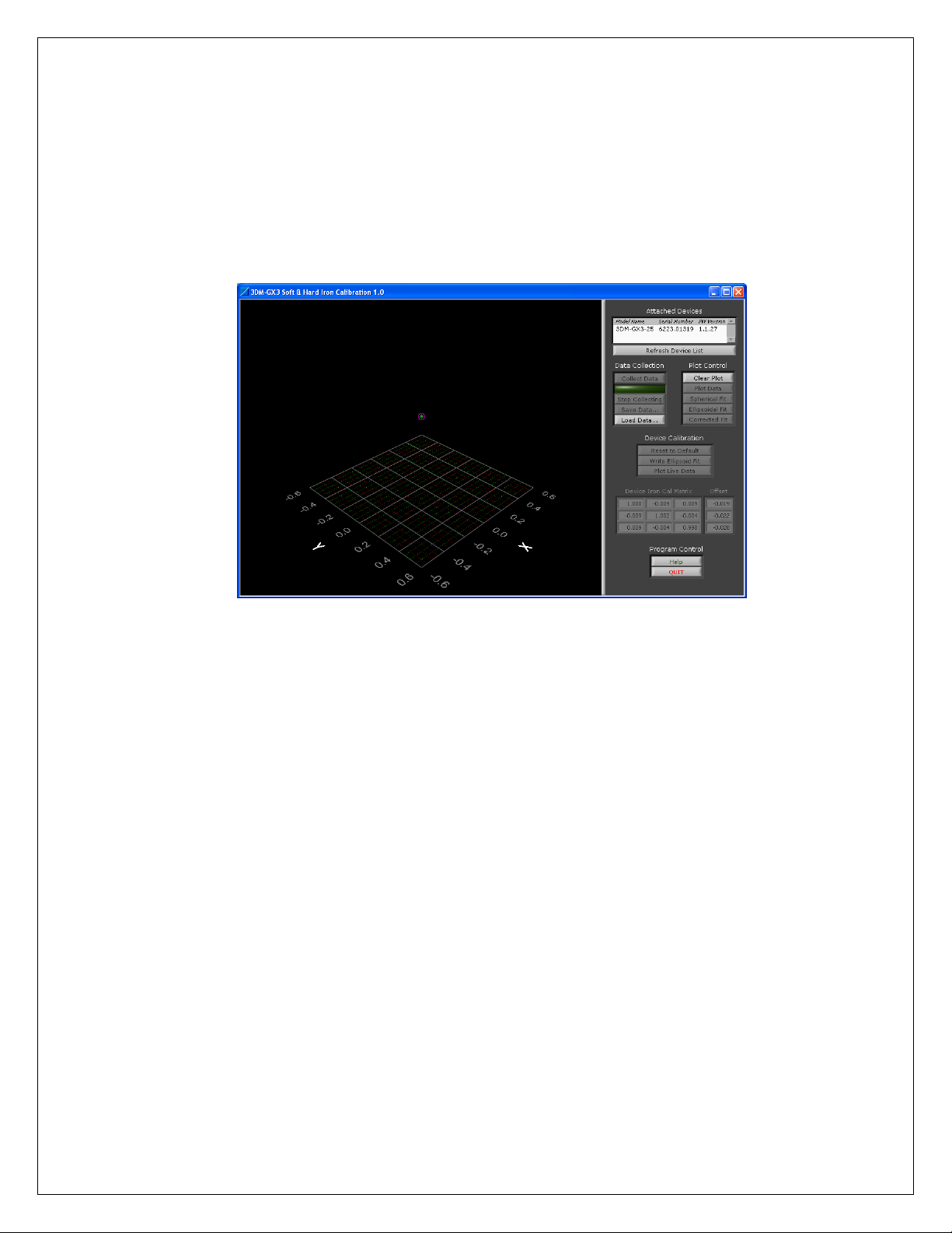
or are hidden and so a field calibration of the magnetometer after final installation is highly
recommended. This can be accomplished using MicroStrain’s MIP Soft & Hard Iron
Calibration software.
Important
If you have a 3DM-GX3®-25 with a firmware version that is lower than 2.0.00, you need to use
the 3DM-GX3®Soft & Hard Iron Calibration. If you have version 2.0.00 or above, you may use
either 3DM-GX3®Soft & Hard Iron Calibration or the MIP Soft & Hard Iron Calibration
software.
Caution
Starting with 3DM-GX3®firmware version 1.1.27, the user has the option of turning off the
heading correction and/or the magnetometer. The default setting is to have both turned on.
Please make sure the magnetometer is turned ON before calibrating.
Instructions
Before starting, make sure you have installed the MIP Soft & Hard Iron Calibration software
from the installation CD or from the installer downloadable at www.microstrain.com.
1) Connect the 3DM-GX3®to your computer using either the RS-232 communication cable
and power supply or the USB communication cable. If you have not already done so,
follow the instructions in the 3DM-GX3®Quick Start Guide on the installation CD to
make sure the device is properly installed and communicating with your computer.

2
2) Launch the MIP Soft & Hard Iron Calibration software.
3) The MIP Soft & Hard Iron Calibration Main window will appear. If you have a 3DM-
GX3®connected, it will appear in the Attached Devices list as shown in Figure 1. If you
add a device after the application has been launched, you must click the Refresh Device
List button for the new device to appear.
.
Figure 1
4) Select the device to calibrate. This enables several of the controls in the screen.
Collecting data is very easy; just follow this basic sequence of calibration steps:
a. Click Collect Data to start collecting data.
b. Move the device in all possible orientations to collect data. As you move the
device, points will appear on the display in 3D.
c. Click Stop Collecting.
d. Click Spherical Fit and/or Ellipsoid Fit to show the calculated calibration result.
e. Click Corrected Fit to show how the corrected data will look.
5) You may repeat this sequence as many times as you wish until you are happy with the
result. Click Write Spherical/Ellipsoid Fit to write the calibration to the device. The
actual calibration values written to the device will be displayed in the Device Iron Cal
Matrix and Offset panels.
6) After writing the calibration, you can view real time calibrated output by clicking Plot
Live Data.
Example
Below is a series of screen shots (Figures 2-7) showing a sample sensor calibration. The sensor
used for this example has a steel nut taped to the housing. As you can see from the screen shots,
this steel nut causes a strong offset and a slight ellipsoid deformation to occur.

3
Figure 2 - Collecting Data
Notice how the purple “star” representing the center of the data sphere is offset from the “circle”
which represents the center of the sensor. Normally, these should be superimposed.
Figure 3 - Spherical Fit
The sphere fits pretty well but some of the points are not on the surface of the sphere.

4
Figure 4 - Ellipsoidal Fit
The ellipsoid fit captures many of the points that were not on the surface of the spherical fit.
Figure 5 - Corrected Fit
The green sphere shows what the calibrated data should look like.

5
Figure 6 - Plot Live Data
The green points represent data taken after the calibration is written to the device. Notice the
values in the Device Iron Cal Matrix and Offset.
Figure 7 - Live Data and Corrected Fit
This shows how the corrected data fits to the ideal sphere.

6
Tips You may interactively rotate the data point display at anytime using the mouse –just
click anywhere in the 3D data display and drag in the direction you would like to rotate.
A context sensitive Help window is available by clicking Help. A window will appear
and the help text will change as you move the mouse over different controls.
The purple “star” represents the center of a sphere that the collected data is creating. This
star changes position often early in the data collection process. If the star stops changing
location as you rotate your sensor about its axis, this indicates that a good estimate of the
magnetic field offset has been determined.
We recommend that you use this tool often during the development of your application.
Mounting changes or changes in surroundings may make a difference in the
magnetometer output and by using this application you can see the magnetic effects and
correct for them as necessary. It will help give you a feel for what effects you need to be
concerned about and which ones are of little concern.
You may save the data collected at any time by clicking Save Data… This will create a
CSV (comma separated records) spreadsheet. You can load saved data using the Load
Data… control to view previously collected and saved data.
For applications that are restricted to 2D motion, the spherical fit is recommended. The
ellipsoid fit requires a greater degree of 3D data.
If your application requires metal mounting hardware or housings, use brass, aluminum,
or 300 series stainless steel. Materials such as steel, iron, ferrite, current carrying
conductors, magnets, etc. should be kept as far as possible from the device.

7
Congratulations!
You are off and running! MicroStrain Support Engineers are always available by phone, email
or SKYPE to assist you in any way we can.
Caution
Do not bring the 3DM-GX3®into contact or close proximity with magnets. Magnets will at a
minimum disrupt the sensor’s operation and can cause permanent damage to its components.
Many GPS antennas have a magnetic base; the antenna we provide does not. If you substitute a
GPS antenna and its base is magnetic, please keep it away from the 3DM-GX3®(and don’t pack
them together).
MicroStrain, Inc.
459 Hurricane Lane, Unit 102 ph: 800-449-3878
8501-0026 Rev 000 Williston, VT 05495 USA fax: 802-863-4093
Copyright © 2012 MicroStrain, Inc. www.microstrain.com support@microstrain.com
MicroStrain® and 3DM-GX3® are registered trademarks of MicroStrain, Inc.
This manual suits for next models
3
Table of contents
Other MicroStrain Network Hardware manuals
Popular Network Hardware manuals by other brands

Axis
Axis S3008 user manual

ADTRAN
ADTRAN DSU 5600 user manual

Huawei
Huawei FusionModule1000A40 ICT Solution Maintenance Guide

Huawei
Huawei SmartAX MA5608T Quick installation guide

NETGEAR
NETGEAR UTM25 - ProSecure Unified Threat Management... installation guide

Tandberg Data
Tandberg Data SUPERLOADER DLT - quick start guide