Microtap Microtap II User manual

Operating Instructions Thread tapping units/ Accessoriesr 01/09, Software 4.9 © 01.1994-2016 microtap GmbH
Operation Instructions
microtap II megatap II
jobtap

Operating Instructions Thread tapping units/ Accessoriesr 01/09, Software 4.9 © 01.1994-2016 microtap GmbH
© copyright microtap GmbH 05.1994 - 2016
All information, know-how and illustrations contained in these operating instructions
are the sole property of microtap GmbH.
Without expressed permission from microtap GmbH neither the entire operating
instructions nor any parts thereof may be communicated directly or indirectly to third
parties, nor may they be copied or used other than for the purpose for which they
are supplied.
General information, list of contents, 1
SAFETY INSTRUCTIONS
Technical data 2
Description
Assembly, 3
Commissioning
Operation machine 4
Maintenance 5
Trouble shooting 6
Spare parts 7
Integration of optional 8
Accessories
Product overview 9
Date of original issue: Version 01.94
Date of this issue: Version 01.16

Operating Instructions Thread tapping units/ Accessoriesr 01/09, Software 4.9 © 01.1994-2016 microtap GmbH 1
TABLE OF CONTENTS
1. GENERAL INFORMATION.......................................................................4
1.1. Declaration of EC-conformity......................................................................................... 4
1.2. Warranty-/Operating procedure Certificate................................................................... 5
1.3. Operating conditions....................................................................................................... 6
1.4. Definitions......................................................................................................................... 6
1.4.1. Viewing definitions .............................................................................................................6
1.4.2. Validity of the operating instructions .................................................................................. 6
1.5. Definition of pictograms.................................................................................................. 7
1.6. Safety instructions........................................................................................................... 8
1.7. Specific operating instructions for the operator.......................................................... 9
1.8. Possible risks to health and safety.............................................................................. 10
2. TECHNICAL DATA, DESCRIPTION.......................................................11
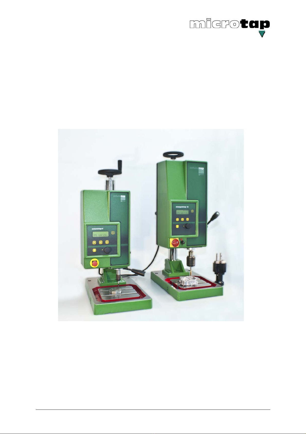
2.1.1. Dimensions megatap II .................................................................................................... 14
2.1.2. Dimensions microtap II .................................................................................................... 15
2.1.3. Dimensions base plate..................................................................................................... 16
2.2. Short description of the machine................................................................................. 17
2.2.1. The automatic thread tapping machine has the following distinguishing features: ......... 18
2.2.2. Rear side of machine head megatap II / microtap II ........................................................ 19
2.3. Thread tapping terms .................................................................................................... 20
2.4. Static fracture torque of taps........................................................................................ 23
3. ASSEMBLY, COMMISSIONING AND RELOCATION............................24
3.1. Off-loading and unboxing ............................................................................................. 24
3.2. Commissioning .............................................................................................................. 25
3.2.1. Location............................................................................................................................ 25
3.2.2. Assembly and commissioning.......................................................................................... 26
3.3. Relocating the machine................................................................................................. 27
3.4. Interfaces, pin-out.......................................................................................................... 28
3.4.1. Connector for lubricating system (receptacle, 4-pins female) ......................................... 28
3.4.2. Serial interface RS 232, SUB-D, 9-pin female................................................................. 28
3.4.3. I/O user interface connector (SUB-D, 15-pins) ................................................................ 29
3.4.4. I/O wiring diagramm (internal wiring of the machine) ...................................................... 30
3.4.5. I/O Samples (external wiring of the machine).................................................................. 32

Operating Instructions Thread tapping units/ Accessoriesr 01/09, Software 4.9 © 01.1994-2016 microtap GmbH 2
3.5. Link between PC and thread tapping machine........................................................... 34
3.5.1. Set of parameters forwarding to the machine.................................................................. 34
3.5.2. Feedback messages of the thread tapping machine....................................................... 35
3.5.3. How to request for specific values ................................................................................... 35
3.5.4. Quality monitoring ............................................................................................................ 36
3.5.5. Remote control mode....................................................................................................... 36
4. OPERATING THE MACHINE..................................................................37
4.1. Changing taps................................................................................................................ 37
4.2. Power Up / working menu............................................................................................. 38
4.3. System Setup ................................................................................................................. 39
4.4. Setting / changing the parameter................................................................................. 40
4.4.1. Operating menu ............................................................................................................... 40
4.4.2. Parameter Menu .............................................................................................................. 40
4.5. Manual operation ........................................................................................................... 48
4.6. Thread tapping with option „ZAP“ via remote control .............................................. 49
4.7. Thread tapping with ZAP-option via RS232................................................................ 50
5. MAINTENANCE ......................................................................................51
5.1. Periodic routine maintenance....................................................................................... 51
5.1.1. Replacing the dust filter (only megatap II, jobtap / labtap): ............................................. 51
6. TROUBLE SHOOTING ...........................................................................52
6.1. General information....................................................................................................... 52
6.2. Fault report form.......................................................................................................... 53
6.3. Quality, error indications............................................................................................... 54
6.4. Opening and closing the machine ............................................................................... 57
6.5. Repairs............................................................................................................................ 58
6.5.1. Replacing the fuse ........................................................................................................... 58
6.5.2. Changing the suspension wires....................................................................................... 58
7. SPARE PARTS .......................................................................................60
7.1. General information....................................................................................................... 60
7.2. Ordering spare parts...................................................................................................... 60
7.3. Spare parts list ............................................................................................................... 61

Operating Instructions Thread tapping units/ Accessoriesr 01/09, Software 4.9 © 01.1994-2016 microtap GmbH 3
8. INSTALLATION OF OPTIONAL EQUIPMENT.......................................62
8.1. MMS Minimum – quantity – lubricant unit.................................................................. 62
8.1.1. MMS with blow out unit .................................................................................................... 64
8.1.2. MMS with impulse control ................................................................................................ 65
8.2. Installation / commissioning the pneumatic feed system (ZAP) to megatap II....... 66
8.3. Depth stop ......................................................................................................................69
8.3.1. Setting of the depth stop .................................................................................................. 70
8.3.2. Working in ZAP mode with depth stop............................................................................. 70
8.4. DSK double spindle head.............................................................................................. 71
8.4.1. Installing double spindle head onto the machine............................................................. 71
8.4.2. Adjusting the hole centres................................................................................................ 71
8.4.3. Installing of collet and tool................................................................................................ 72
8.4.4. Maintenance.....................................................................................................................72
8.5. LSM Air seal for exit of motor spindle......................................................................... 73
8.5.1. Mounting of air seal.......................................................................................................... 73
8.6. Air Blast unit................................................................................................................... 75
9. PRODUCT OVERVIEW...........................................................................76
9.1. Options and accessories for the thread tapping machine ........................................ 77
9.2. Quick change inserts..................................................................................................... 78
9.3. Collets – Accessories.................................................................................................... 79

Operating Instructions Thread tapping units/ Accessoriesr 01/09, Software 4.9 © 01.1994-2016 microtap GmbH 4
1. General information
1.1. Declaration of EC-conformity
in view of EC-standard machines 2006/42/EG (89/392/EWG, appendix II A)
89/392/EWG
We, microtap GmbH
Rotwandweg 4
82024 Taufkirchen / München
Germany
declare that the machine, described in the following, is due to its concept and design and in
the form and version distributed by us conforms to all relevant safety- and health related EC-
regulations.
This declaration is void if alterations are performed on the machine without prior agreement
with microtap GmbH.
machine term: Tapping machine
machine type: microtap II / megatap II / labtap / jobtap
machine serial No.: xxxxxx - x
Applied EC-standards: EC-machine regulation 2006/42/EG (89/392/EWG)
EC-low voltage regulation 2006/95/EG (73/23/EWG)
EC-regulation electromagnetic compatibility 2004/108/EG
(89/336/EWG)
Applied harmonized standards: EN 60 204-1; 1997 1992
DIN EN 292 T1,T2
DIN EN ISO DIN EN 294
DIN EN 349
DIN 8418
Date / signature of producer/legal representative: January 2016
Information to the undersigner: Company owner/president: Klaus M. Müller

Operating Instructions Thread tapping units/ Accessoriesr 01/09, Software 4.9 © 01.1994-2016 microtap GmbH 5
microtap GmbH
Service department Tel.: +49-89-6128051
Rotwandweg 4 Fax: +49-89-6127488
82024 Taufkirchen
Germany
1.2. Warranty-/Operating procedure Certificate
With your torque controlled thread cutting machine
and together with the operating instructions as well as our delivery- and payment-
conditions you are receiving this confirmed manufacturer warranty document.
Hereby microtap GmbH, Taufkirchen, will be liable as manufacturer to grant a 12
month warranty according to the product-liability law dated 01.01.89 and in the
range of our own delivery conditions provided that the copy of this warranty-
certificate will be returned to us immediately after taking the a.m. machine into
operation.
By sending this certificate with your signature back to us, you acknowledge the
receipt of a.m. machine including operating instructions and CE-certificate in good
condition.
Received goods:
Machine-type: ............................. Serial-Nr.: .............................
Invoice-/Delivery Note No.:................ Software Version: .............................
Buyer/Company name with legal form:
Name .............................................Stamp:
Street: .............................................
Address: .............................................
Taking a.m. machine into operation acc. to delivered instructions:
Name: ............................................. Signature: .............................
Date: .............................................

Operating Instructions Thread tapping units/ Accessoriesr 01/09, Software 4.9 © 01.1994-2016 microtap GmbH 6
1.3. Operating conditions
The „microtap II“ versions G2, G5 and jobtap G5 and “megatap II” versions G8, G14,
-G16, jobtap G8, -G14, -G16 and labtap G5, -G8 automatic thread tapping machine
and its optional accessories are state-of-the-art design and meet all relevant safety
regulations.
All versions of the thread tapping machine must be used only in the upright position
unless specifically equipped for horizontal operation for the following purposes:
- for thread tapping operation in low- or high volume batches
- as a reference machine for establishing optimum tapping process parameters
- for thread inserts (ENSAT, HELICOIL)
- for torque controlle screwing
Any other utilisation is contrary to its purpose and not allowed.
The manufacturer expressly excludes all responsibility for damage or injury caused
by improper use or failure to observe these operating rules; in such event the user
shall bear full responsibility.
The machine must be assembled, operated, maintained and repaired only by
authorised and trained personnel allocated to the task.
The safety equipment attached to the machine must not be modified or disabled.
Retrofits or modifications of the machine may be carried out only following prior
agreement with and in accordance with instructions issued by microtap GmbH. The
user shall bear full responsibility for any unauthorised retrofits or modifications.
1.4. Definitions
In these operating instructions various types of information is provided. The type of
information provided is identified by the following symbols, whose purpose must be
adhered to under all conditions.
1.4.1. Viewing definitions
The terms front, back, left, right, top and bottom refer to the parts of the machine as
seen from the operating position. The operating lever, for instance, is on the right
side of the machine.
1.4.2. Validity of the operating instructions
Unless otherwise stated, these operating instructions are valid for the „microtap II“
versions G2, G5 and jobtap G5 and “megatap II” versions G8, G14, -G16, jobtap
G8, -G14, -G16 and labtap G5, -G8 automatic thread tapping machines and their
listed optional accessories.

Operating Instructions Thread tapping units/ Accessoriesr 01/09, Software 4.9 © 01.1994-2016 microtap GmbH 7
1.5. Definition of pictograms
The following pictograms are used in these operating instructions.
Danger! High voltage!
Disconnect mains power supply!
Wear breathing protection!
Protect the environment!
NOTE
This symbol identifies technical features which, if disregarded, can result in machine
errors.
CAUTION
This symbol identifies operating instructions which must be followed exactly to avoid
damage to the machine, its control system or peripheral system components.
WARNING
This symbol identifies operating instructions which must be followed exactly to avoid
risks of injury to personnel; it includes the definition of CAUTION.
Failure to observe such instructions may lead to death or severe injury.
Manufacturer’s hint
This symbol identifies hints and tips offered by the manufacturer, which the operator
may find useful.

Operating Instructions Thread tapping units/ Accessoriesr 01/09, Software 4.9 © 01.1994-2016 microtap GmbH 8
1.6. Safety instructions
The thread tapping machine and its optional accessories are state-of-the-art design
and conform to all relevant safety regulations.
They may however due to their nature give rise to safety risks if they are operated
incorrectly by untrained personnel or not in accordance with the operating
instructions.
Operating risks can only be eliminated by proper operation.
All relevant general safety regulations (in Germany VBG ...) must be observed and
complied with.
• Risk of electric shock
- through contact with conducting components through assembly of the
machine (EN 60204/VDE 0113)
- through contact with conducting components following inexpert maintenance
(VBG 4).
• Risk of thermal shock
- by touching the tap immediately after the tapping process.
• Risk from materials of components or work materials
- through contact with liquids, oils and greases or by inhaling gases, vapours
and dusts.
- The relevant instructions for use by manufacturers of lubricants and cleaning
materials must be complied with.
- See also the relevant safety data sheets.
• Risk due to not following operating instructions.
- do not carry out unauthorised work on or with the machines.

Operating Instructions Thread tapping units/ Accessoriesr 01/09, Software 4.9 © 01.1994-2016 microtap GmbH 9
1.7. Specific operating instructions for the operator
Following are some basic safety instructions, which must be observed.
• Any person who may have to deal with the automatic thread tapping machine
must first read and understand these operating instructions and in particular this
section.
• Never touch the spindle if the machine is plugged into an electric supply socket.
Before changing a tap, switch the drive off by means of the drive selector
switch.
• Always wear eye protection when operating the machine.
• Avoid any action which may impair the safety of the machine.
• Check the location of the EMERGENCY-STOP button and the main switch to
ensure that you can react quickly to any emergency.
• Wear clothing which cannot catch in moving parts of the machine. Button the
cuffs of your shirt or jacket, or turn them under inwards.
• If you wear long hair or a scarf, arrange them so that they stay out of the danger
zone. Long hair may have to be gathered under a hairnet. Tuck in the ends of
ties and scarves.
• Do not work on or with the machine if your level of attention is reduced by any
drug.
• It is the user’s responsibility to make sure that no unauthorized persons are
working with the machine.
• Anyone operating the machine must immediately report any changes of or with
the machine which may have an impact on its safety.
• The management of the user company is under the obligation to operate the
machine only if it is technically sound; faults which may impair safety of
operation must be rectified immediately.
• The management of the user company must ensure a proper work place
environment through appropriate work regulations and inspections.
• The management of the user company must, if necessary, request operators to
wear suitable protective clothing.
• Only qualified personnel may work on the electrical parts of the machine!
• Water protection!
Ensure that lubricants, cleaning compounds and other substances do not enter
the waste water drain, nor ground water or soil.
• Under no circumstances must safety equipment installed to the machine be
dismantled or disabled.
- During repairs or maintenance, the following e x c e p t i o n applies:
Before dismantling safety equipment for repairs or maintenance, take the
machine out of operation according to the instructions.
Immediately after completion of any repair or maintenance work, reassemble
the safety equipment and guards. Any faulty or broken parts must be
replaced!
• When the machine is operated remotely, ensure that no one can enter the work
envelope of the machine.
• Through the use of safety fences, light guards and other means of barriers, the
machine has to be guarded in such a way that anyone entering this area will
cause the machine to be shut down instantly.
• Worn or damaged tools must not be used. Replace them with properly
functioning tools.

Operating Instructions Thread tapping units/ Accessoriesr 01/09, Software 4.9 © 01.1994-2016 microtap GmbH 10
1.8. Possible risks to health and safety
Lubricants, safety materials and cleaning substances.
Careless use of these materials or neglect of safety and health regulations can
endanger your health and especially the skin.
Safety instructions
The instructions given in the safety documentation of the manufacturers must be
complied with!
• Wear protective gloves and protective clothing.
• Do not use open flames!
• Avoid skin contact to eliminate skin irritation!
• Apply barrier cream before starting work.
• If your skin comes into contact with lubricants, safety materials or cleaning
fluids, immediately wash the affected part with soap and water or apply a
greasy skin cream.
• Provision must be made to avoid lubricants and safety materials from getting
into the waste water drains.
Safety instructions
Every container of lubricant or ancillary material (for instance cleaning solution) is
suppplied with safety data sheets.
These data sheets contain information about the chemical composition of the
material, its safe transport, storage, handling, disposal and appropriate treatment in
the event of an accident or fire.
Insert after this chapter the safety data sheets from all manufacturers whose
materials are to be used with the machine.

Operating Instructions Thread tapping units/ Accessoriesr 01/09, Software 4.9 © 01.1994-2016 microtap GmbH 11
2. Technical data, description
Type
• Version Thread tapping machine
• Description microtap II-G2
microtap II-G5/jobtap/labtap
megatap II-G8/jobtap/labtap
megatap II-G14/jobtap
megatap II-G16/jobtap
Media supply
• Operating voltage, standard 230 VAC ± 10 %
version microtap II, optional 115 VAC ± 10 %
• Frequency 50/60 Hz
• Power consumption
Version microtap II - G2 max. 200 W
Version microtap II - G5 / jobtap / labtap max. 300 W
Version megatap II / jobtap / labtap max. 2.900 W
• Line fuse version microtap II 115 V 6,3A / T (Circuit breaker)
version microtap II 230 V 3,15A / TT (Circuit breaker)
version megatap II 230 V 16 A / T (Circuit breaker)
• Dry compressed air (ZAP-mode) min. 2 bar (58 psi)
max. 8 bar (116 psi)
• Dry compressed air (drop / spray - mode) min. 4 bar (58 psi)
max. 8 bar (116 psi
• Torque rates
- Version microtap II-G2 2 to 65 Ncm
- Version microtap II-G5 / jobtap / labtap 5 to 220 Ncm
- Version megatap II-G8 / jobtap / labtap 50 to 700 Ncm
- Version megatap II-G14 / jobtap 120 to 1.680 Ncm
- Version megatap II-G16 / jobtap 150 to 2.100 Ncm
• Cutting speeds
- Version microtap II-G2 150 to 1.000 min-1 (RPM)
- Version microtap II-G5 / jobtap / labtap 250 to 2.200 min-1 (RPM)
- Version megatap II-G8 / jobtap / labtap 300 to 3.000 min-1 (RPM)
- Version megatap II-G14 / jobtap 125 to 1.250 min-1 (RPM)
- Version megatap II-G16 / jobtap 100 to 1.000 min-1 (RPM)
• Spindle travel microtap II / jobtap / labtap max. 65 mm
megatap II / jobtap / labtap max. 85 mm
• reachable thread depth
microtap II / jobtap / labtap max. 45 mm
megatap II / jobtap / labtap max. 75 mm
• Reachable tolerance of measuring 0,1 mm
(without allowance of tool holder)

Operating Instructions Thread tapping units/ Accessoriesr 01/09, Software 4.9 © 01.1994-2016 microtap GmbH 12
Dimensions, weights
Dimensions over all approx. (L x W x H in mm)
• microtap II / jobtap / labtap
- with column 600 mm 510 x 323 x 808
- with column 750 mm 544 x 312 x 1047
• megatap II / jobtap / labtap
- with column 750 mm 544x312x1047
- With higher column the dimensions add for the difference of the high of the
column.
• Weights approx.: in kg
- base plate 20,5
- Column cpl. 600 mm 12,8
- Column cpl., 750 mm 14,2
- Column cpl., 1.000 mm 16,5
- Machine head, microtap II-G2 16,1
- Machine head, microtap II-G5 / jobtap / labtap 18,1
- Machine head, megatap II-G8 / jobtap / labtap 27,0
- Machine head, megatap II-G14/-G16 / jobtap 28,6
Tool attachment system
• Machine type Spindle Tool holder
microtap II-G2 B6 Collet change system SZS0
microtap II-G5 / jobtap / labtap B10 Quick tool change system SWS0
megatap II-G8/ jobtap / labtap B12 Quick tool change system SWS1
• megatap II-G14 / jobtap B12 Quick tool change system SWS2
• megatap II-G16 / jobtap B12 Quick tool change system SWS3
ATTION!
The machine is delivered with the chuck heat-shrunk to the spindle; it must not be
removed by the user, since this may damage the spindle bearing.
Work envelope
• Vertical envelope in Z-direction (without tool)
Type of column microtap II megatap II G8 megatap II G14 /16
600 mm approx. 280 mm approx. 250 mm approx. 238 mm
750 mm approx. 430 mm approx. 400 mm approx. 388 mm
1000 mm approx. 680 mm approx. 650 mm approx. 638 mm

Operating Instructions Thread tapping units/ Accessoriesr 01/09, Software 4.9 © 01.1994-2016 microtap GmbH 13
• Cutting capacity
- microtap II-G2 M 0,5 - M 2 (X5CrNi189)
(Metric ISO-standard thread); M 0.5 - M 2,5 (9SMn28)
DIN13/sheet 34 M 0.5 - M 3 (AlCuMgPb)
- microtap II-G5 / jobtap G5 / labtap M 1.0 - M 5 (X5CrNi189)
(Metric ISO-standard thread); M 1.0 - M 6 (9SMn28)
DIN 13/sheet 34) M 1.0 - M 6 (AlCuMgPb)
- megatap II-G8 / jobtap / labtap M 2.5 - M 8 (X5CrNi189)
(Metric ISO-standard thread); M 2.5 - M 10 (9SMn28)
DIN 13/sheet 34) M 2.5 - M 12 (AlCuMgPb)
- megatap II-G14 / jobtap M 3.5 - M 12 (X5CrNi189)
(Metric ISO-standard thread); M 3.5 - M 14 (9SMn28)
DIN 13/sheet 34) M 3.5 - M 18 (AlCuMgPb)
- megatap II-G16 / jobtap M 4 - M 14 (X5CrNi189)
(Metric ISO-standard thread); M 4 - M 16 (9SMn28)
DIN 13/sheet 34) M 4 - M 20 (AlCuMgPb)
Peripheral operating conditions
• Room temperature for the machine 0 to 60 °C (32 to 140 °F)
• Isolation IP 44
• Continuous noise emittance; 70 dB(A)
(measured with continuous ZAP-operation)
(Reference meter: Onsoku Sand Meter SM-6)
Control system, interfaces (not for jobtap)
• PLC-compatible control 4 Bit Input, 4 Bit Output,
parallel, galvanically isolated
• Interfaces RS 232, 9600 Baud, 8 Bit, no parity,
1 stop bit,galvanically isolated
• Operation menu driven, display 4-lines
Paint finish
microtap II / megatap II emerald green, RAL 6001
jobtap emerald green, RAL 6001
labtap bright ivory, RAL 1015

Operating Instructions Thread tapping units/ Accessoriesr 01/09, Software 4.9 © 01.1994-2016 microtap GmbH 14
2.1.1. Dimensions megatap II
Fig 2-1 Dimensions megatap II / jobtap / labtap (unit: mm)

Operating Instructions Thread tapping units/ Accessoriesr 01/09, Software 4.9 © 01.1994-2016 microtap GmbH 15
2.1.2. Dimensions microtap II
Fig. 2-2 Dimensions microtap II / jobtap-G5 / labtap-G5 (unit: mm)

Operating Instructions Thread tapping units/ Accessoriesr 01/09, Software 4.9 © 01.1994-2016 microtap GmbH 16
2.1.3. Dimensions base plate
Fig 2-3 Dimensions: Standard base plate for all thread tapping machines
Threaded connection G ¼ (PG6) for reassembly of lubricants.

Operating Instructions Thread tapping units/ Accessoriesr 01/09, Software 4.9 © 01.1994-2016 microtap GmbH 17
2.2. Short description of the machine
Fig 2-6 Front view megatap II / jobtap Fig. 2-7 Front view microtap II-G5 /
jobtap G5
1 Base plate 7 Setting lever for retracting force on
drive spindle (counter-balance)
2 Height adjustment (column) 8 Drive spindle
3 Thread tapping unit 9 Quick-change collet holder
4 Crank for height adjustment 10 control panel and display screen
5 Clamp handle for height adjustment 11 EMERCENCY STOP switch
(megatap II = main switch)
6 Operating lever with start button 12 Motor ON/OFF switch

Operating Instructions Thread tapping units/ Accessoriesr 01/09, Software 4.9 © 01.1994-2016 microtap GmbH 18
2.2.1. The automatic thread tapping machine has the following distinguishing features:
Height adjustment (column) 600 mm, 750 column, 1.000 mm
The machines can be equipped with different columns. Column 600 (standard
microtap II,) 750 mm (standard megatap II); the height of the work head is adjusted by
a hand crank after releasing the locating clamp. The work head can not be rotated
horizontally.
Operating lever with integrated start button, for manual operation.
The operating lever has an adjustment provision for its length. It can also be
disengaged from the feed drive. This helps to prevent accidents when the machine is
operated with the pneumatic feed control (ZAP).
Floating (weight-balanced) suspension of motor (work spindle).
The weight of the work spindle is equally balanced over its entire travel; the spindle
operation is by hand lever or pneumatic pressure. After the start of the cut, no force is
applied in the feed direction; the cutting tool advances into the workpiece solely by
virtue of its pitch. The return force on the operating head is adjustable.
The drive spindle of the motor is also the work spindle,
which ensures a very quick reaction time to prevent tool fracture and permits an
accurate measurement of the applied torque.
The megatap II-G14/-G16 / jobtap G14 /-G16 includes a gearbox between the drive
motor and the work spindle.
Continuous monitoring of torque of drive motor;
The torque is limited to the value preset by the operator and is continuously indicated
on the operator display. The torque is monitored to prevent fracture of the tool, to
provide, for instance, a measure of tool quality and tool life, or indication whether
lubricant is needed or whether the selected cutting speed is correct, or whether the
hole is too large or too small.
Quick-change collet holder (quick tool change system SWS) (see chapter tool
holder).
The machine is delivered with the chuck heat-shrunk to the spindle; it must not be
removed by the user, since this may damage the spindle bearing.
The quick-change inserts are sized to suit the diameter of the cutting tools. The
inserts do not retain the cutting tool rigidly but permit limited axial backlash. The
cutting tool is thus self-centering in the hole and can compensate positional deviation
approx. 0,1mm.
Control panel (see chapter “operating machine”)
The control panel incorporates-a 4-line display, a sealed keyboard with 5 selector
buttons and a rotary knob
The ON/OFF selector switch (only megatap II)
If the machine is in automatic mode (START AUTO Sz), the selector switch must be
set to “0” before attempting to change the tapping tool.
The screen displays the message “SAFETY STOP, MOTOR DISABLED”.
WARNING Risk of injury!
When the machine is in automatic mode, the spindle starts automatically when the
work head is advanced towards the workpiece.
This manual suits for next models
2
Table of contents
Popular Industrial Equipment manuals by other brands

Kenco
Kenco KL16K8T18 Operator's manual

R.V.R. Elettronica
R.V.R. Elettronica TJ5KPS user manual

PISCO
PISCO VK Series manual

KWM Gutterman
KWM Gutterman IronMan Operating and Maintenance Troubleshooting Guide

Merax
Merax Z1T - R2 Operation manual

Jeil Mtech Co., Ltd.
Jeil Mtech Co., Ltd. Marksman MK-100N user manual