Helbling & Co Facette Star 500 User manual

Instruction manual
Instruction Manual
Chamfering Machine
500
Technical data, Facette Star 500, Part no. W03.00000
Supply voltage 230 V 50Hz / 110V 60Hz
Motor power Input 500W 650W Output 500W
Speed regulation 1‘200 bis 8‘000 min
-1
stepless
Carriage stroke 500 mm
Table support surface
L: 760mm
B:120 x 43 mm
Chamfer height in one operation 0.1-5 mm stepless (see 3.10)
Workpiece thickness min. 1mm
Workpiece weight max. 20 kg
Machine weight 58 kg
Housing and controller are earthed.
Standard equi ment included
Je 1
Allen key 6 / 8 / 10
2
Keys to Emergency stop button
1
Connection cable available for CH/EU/GB/US

Helbling & Co. AG März 2021
Safety instructions
Read the operating instructions before commissioning.
Wear protective goggles.
Wear hearing protection.
Do not touch the rotating cutter. It may cause injury.
Do not wear gloves when milling.
Attention: If the table is folded up while the machine is
running the machine is automatically switched off by the
inductive limit switch (76). When the table is in the working
position again the machine can be restarted with the start
button (78).
Attention: The weight of the machine is approx. 58 kg.

Helbling & Co. AG März 2021
Intended use
The chamfering machine is intended exclusively for milling bevels and edges. The parts
must not weigh more than 20 kg and can be made of different materials (aluminium
steel stainless steel plastic etc.).
The machine may only be used in accordance with its intended purpose. Any other use
beyond this is prohibited.
Part of the intended use is also the observance of the safety instructions as well as the
commissioning and the mode of operation in the operating instructions.
The manufacturer accepts no liability for damage caused by improper or incorrect use.
Only accessories and spare parts from the manufacturer's range may be used.
Persons who operate the chamfering machine and carry out maintenance work must be
familiar with it and informed about possible dangers. In addition the applicable accident
prevention regulations must be strictly observed.
Bridging of safety elements and modifications to the machine exclude any liability on the
part of the manufacturer and any resulting damage.
All other applications are expressly excluded and are considered as non-intended use.
Esidual risks
As with all machines there are dangers inherent in the operation and handling of this
machine. Attentive operation and correct handling of the machine significantly reduce
possible accident hazards. If the normal precautionary measures are disregarded
accident hazards may arise for the operator.
Behaviour in case of malfunctions and accidents
Immediately press the ON/OFF switch (75) see Fig. 1 and pull out the mains plug.
This deburring machine is built according to
the directives 2006/42/EC + 2014/30 EU and
is spark suppressed.

Helbling & Co. AG März 2021
1.
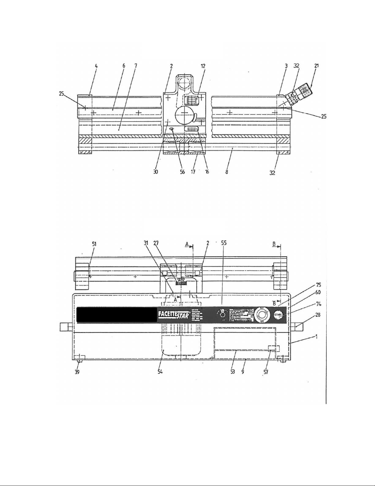
Installation (fig 1)
1.1
The machine weighing approx. 58 kg (110 V model 128 lbs) is easily hand
carried by two people. Reach for the two handles (28) to lift the machine and
place it on a solid table or trolley with lockable cast. Ideal table heigt 75 cm
(30").
1.2
Loosen knurled screw (27) by one quarter of a revolution and lift the sliding
table with both hands until it rests against the support block (2). Remove
protecting covers above supporting ball bearings (12 and 16). Lower sliding
carriage carefully in original position and check if carriage can be moved freely
over full length of stroke from stop to stop.
1.3
The chips are ejected through an opening in the elbow cover (2) at the back of
the machine. Place a box in this area or install a suction device (optional
equipment) to collect the chips and keep the working place clean.
1.4
Connect the cable to single phase power source 230V 650W (USA: 110V
650W)
2.
Safety Instructions
2.1
Read all these instructions before attempting to operate this product and save
these instructions.
2.2
Don't use tools for purposes for which they are not intended.
2.3
Watch what you are doing. Use common sense. Do not operate tool when you
are tired.
2.4
Do not wear loose clothing. They can be caught in moving parts. Wear
protective hair covering to contain long hair.
2.5
Before use of the tool check for physical damage to ensure that it will operate
property and perform its intended function.
2.6
Use safety glasses and earmuff before turning it on "70 dB (A)"
3.
O eration (fig. 1 and 2)
3.1
Move sliding table fully to the ris ht until it contacts the stop.
3.2
Adjust micrometer screw (21) for setting chamber height to the required scale
position (one graduation = .05 mm - 0.002"). E.g. if screw is adjusted to "1 0"
a chamfer of 1 mm (.040") height x 45° will result.
3.3
To check the machine we recommend as follows:
-
Place a block of aluminium size approx. 3" x 3" x 1" on carriage
-
Adjust micrometer screw to "1 0".
-
Unlock danger-stop-button (75) with the key (one quarter of a revolution
on the right). Pull out the key with one quarter of revolution on the left and
place the key in safety. (Attention: Don't push the danger-stop-button!)
-
Turn the speed adjusting knob (55) to the position 8 (6'500 RPM).
-
Push start-button (74)

Helbling & Co. AG März 2021
3.4
Read from plate (60) the recommended position of the speed adjusting knob (55)
for the material used and turn knob to this position.
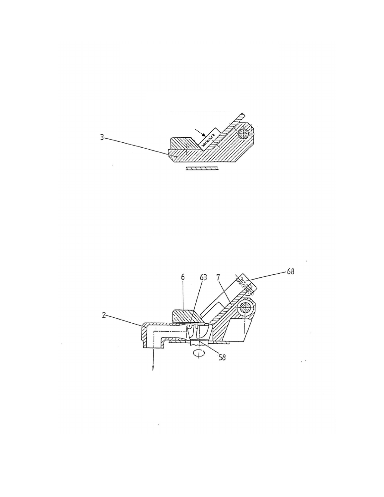
3.5
Move carriage fully to the right and place the piece to be chambered in the
approximate center of the carriage. Push piece with both hands into the "V"
formed by rail (6) and plate (7) (see fig. 2) and more it together with the sliding
table to the left past the milling cutter. Remove workpiece and check chamfer.
3.6
Move carriage to the right for each new working stroke.
3.7
Small work ieces can easily and precisely be squared with the stop gauge (68
standard equipment). That gauge clamped to the table at any position can also
be used as a pusher bar and retains the workpiece firm in place what-ever the
milling pressure will be.
3.8
Thin work ieces up to 500 mm (approx. 20") long 1 to 5 mm (.04 to 2") thick
can be clamped on overall length during the working procedure with a
holddown unit (optional equipment see leaflet). Min. thickness of workpiece: 1
mm (.040").
3.9
Longer work ieces than 500 mm (20") can be fed along the stationary carriage
"V" past the cutter after having the carriage centered and locked.
3.10
Max. chamfer height in one pass on:
- Mild steel aluminium nonferrous etc.
5 0 mm (.2")
-
Alloyed or stainless steel 2 5 mm (.I ")
-
Heat treated steel with hardness above
57° RC (with CBN grinding head) 0 6 mm (.024")
3.11
The workpiece supporting plates (6 and 7) are made of heat treated steel to avoid
damage to their surfaces.
3.12
Machine turn ON / OFF
Normal case: Off: Stop machine by turning speed knob (55) back to “0”. The
spindle brake stops it immediately.
On: Restart the machine with speed knob (55) to the desired
speed
Danger case: Off: Push stop-button (75) (the danger-stop-button will only
operate
When the key is pulled out) The motor spindle brake stops it
Immediately. Start-button (74) is no longer alighted.
On: To unlock the danger-stop make it possible only with the key
(one quarter of a revolution on the right). Pull out the key with
one
quarter of a revolution on the left and place
the key in safety.
(Attention:
Don't push the danger-stop-
button!)
Push start-button; the motor turn again.
3.13
When lifting the sliding
carriage the electric current is automatically interrupted
by a
proximity switch (56) and the motor will stop immediately. To restart the machine the
sliding carriage has to be brought back into working position. Then the speed
adjusting knob (55) must be reset to "0" before returning to the desired
speed.
3.14
Whenever the sliding table has been lifted check prior to lowering it in working;
position if the bottom side of the carriage and its supporting ball bearings are clean
to prevent chatter or unequal chamfers
3.15
When in trouble see paragraph 7 (trouble Shooting)

Helbling & Co. AG März 2021
4.
Maintenance (fig. 1 and 2)
4.1
The machine does not require any maintenance. We recommend
however to lightly oil the guide bar (8) from time to time.
4.2
When cleaning the machine be careful to avoid allowing chips to fall
between the support ball bearings (12 and 16) and the sliding table
bottom side.
4.3
For spares see paragraph 10.
5.
Trans ort (fig. 1)
5.1
For safety reasons whenever transport is required clamo sliding
carriage in approx. center position with knurled screw (27).
5.2
Place cardboard strip or similar protective material between supporting
ball bearings and sliding table plates to prevent plates from getting
marked.
6.
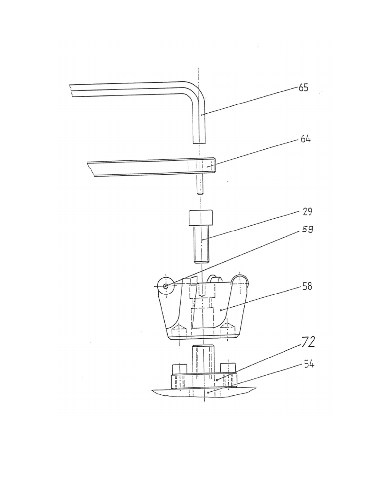
Tool changing (fig. 3 and 4)
6.1
Keep cutter (58) in position with the special pin wrench (64) and remove screw
(29) with hex. wrench (65) - see fig. 3.
6.2
Slide cutter off the spindle (54) by hand. If it sticks pry it loose from motor
spindle by inserting a screw (67) in the tapped hole of the cutter (see fig. 4).
6.3
The milling cutter should be removed when changing or turning the inserts.
6.4
Loosen the screws (59) using the Torx key T20. Remove the inserts and
clean the seats and inserts.
6.5
Rotate inserts 30° compared to the already used section to fully use the
cutting edge all around. Tighten centre screw and make sure that inserts
are well seated.
6.6
Place cutter on motor spindle (54) so that the drive screws (72) are
engaging the drive holes of the cutter (58).
6.7
Hold cutter in position with special pin wrench (64). Insert screw (29) and
tighten it firmly with hex. key (65).
6.8
The assembly and disassembly of other cutters or the grinding head
(optional equipment) is done the same way

Helbling & Co. AG März 2021
7.
Trouble shooting

Helbling & Co. AG März 2021
8.
Spares (fig. 1 - 4)
Pos. description Article-Number
1
Housing
W03.01001
2
Carriage holder complete
W03.04100
3
Carriage holder right
W03.04501
4
Carriage holder left
W03.04502
6
Chamfer adjustment rail complete
W03.04700
7
Support plate complete
W03.04800
8
Shaft to ball bush
2.0088.00086
9
Base plate
W03.04001
12 Large bearing pedestal complete with felt wiper
W03.04200
16 Small bearing pedestal complete with felt wiper
W03.04300
17 Ball bushings (2 pieces)
2.0088.00087
21 Adjustment complete
W03.04600
25 Sliding blocks complete (2 pieces)
W03.04702
27 Cordell handle complete
W03.04102
28 Bow handle (2 pieces)
2.0088.00088
29 Hexagon socket screw M 10x25
30 Hexagon socket screw M 10x45 (4 Stück)
31 Hexagon socket screw M 6x20 (6 Stück)
32 Hexagon socket screw M 6x20 (6 Stück)
39 Apparatus buffer 2.0088.00089
51 O-rings (2 pieces) 2.0088.00090
53 FU-V2-134Hz 230V / 50Hz
W03.02301
54 MF-V2-134Hz-Motor 230V / 50Hz W03.02500
55 Switch potentiometer complete
W03.02200
55 Speed control knob complete
2.0088.00066
56 Inductive limit switch
W02.02300
57 Mains plug with filter
2.0088.00010
58 Cutter head (see price list)
59 Countersunk screw for cutter head
W10.5001.000/2
60 Front panel complete
W03.03000
63 Inserts (see price list)
64 Pin hole spanner for cutter head with square inserts W10.5001.002
64 Pin hole spanner for cutter head with round inserts W10.5002.002
65 Allen key SW 8 mm
66 Allen key SW 10 mm
67 Hexagon socket screw M12x40
68 Stop
W07.08200
72 Motor flange with mounted screws
74 Start button (illuminated)
W03.02400
75 Emergency stop mushroom button complete with cable
W03.02100
Connection cable CH/EU/GB/US
Helbling & Co. AG März 2021
fig. 1
Details see fig. 2
Details see fig. 2
FRONT VIEW
VIEW ON TOP
Helbling & Co. AG März 2021
fig. 2
fig. 3
SECTIONAL DRAWINGS
RELATING TO FIG. 1
SECTION B - B
Work iece
SECTION A - A
CHIPS
Helbling & Co. AG März 2021
ASSEMBLY AND DISASSEMBLY OF TOOLINGS
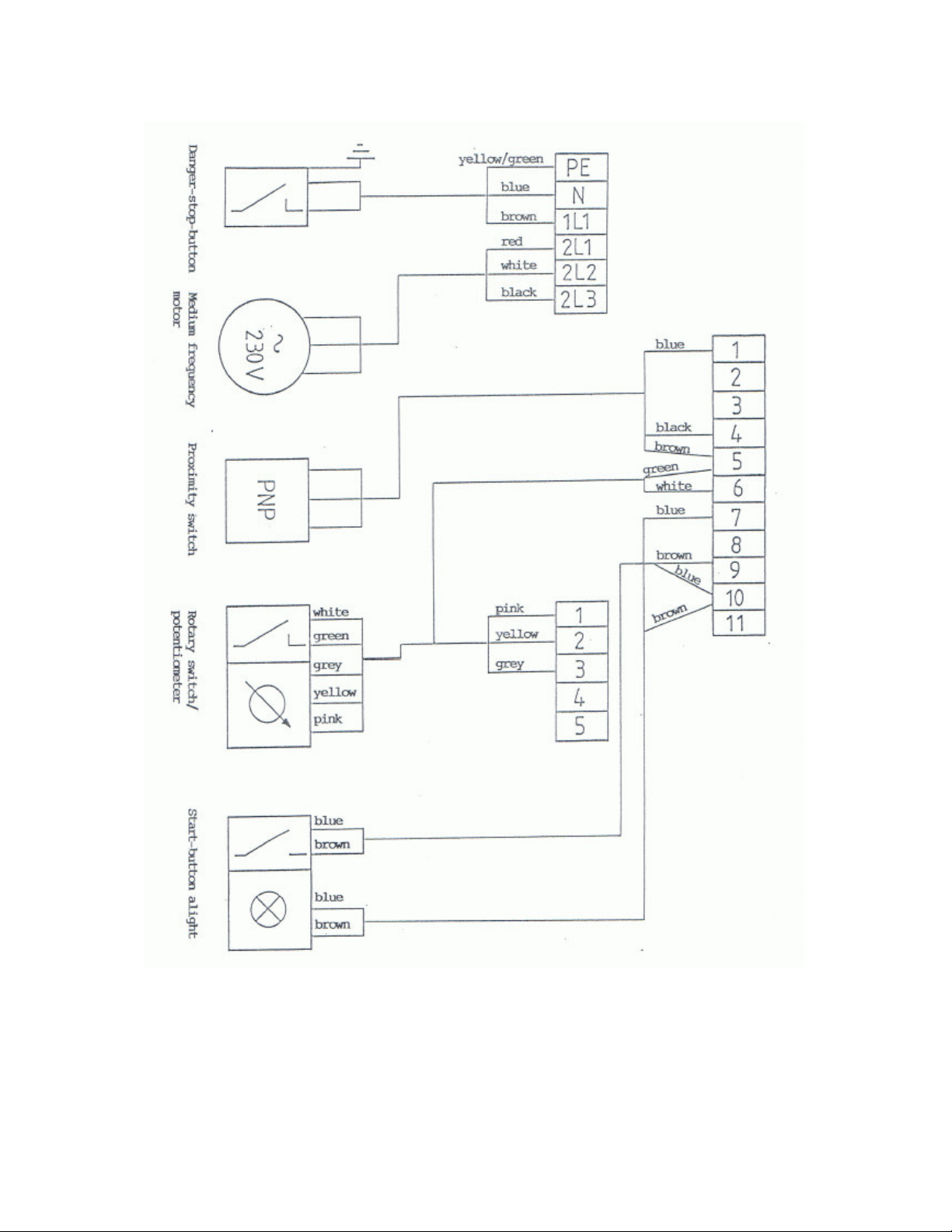
fig. 4 Wiring Diagramm
Helbling & Co. AG März 2021
This manual suits for next models
2
Table of contents
Popular Industrial Equipment manuals by other brands


turck
turck RA-SAB-15-36 quick start guide

Neco
Neco STIR-RITE III Owner's/operator's manual

INOXPA
INOXPA KIBER KSF Ex Installation, service and maintenance instructions

WAMGROUP
WAMGROUP VN Instructions for using

Swegon
Swegon COLIBRI Free a Installation, commissioning maintenance

SCHUNK
SCHUNK PWG-plus Series Assembly and operating manual

Samoa
Samoa 391020.270 Parts and technical service guide

EMUGE
EMUGE Speedsynchro Modular/NFC Operating instruction

Apex Digital
Apex Digital A95 OPERATING & SERVICE MANUAL

ensto
ensto EFPLP5 installation instructions

PCB Piezotronics
PCB Piezotronics M352C66 Installation and operating manual

Lenze
Lenze ELN Mounting instructions