CNC PYTHON XPR User manual

[USER GUIDE]

All rights reserved. This manual may not be reproduced or distributed, in whole or in part, without the prior written permission from CNC Factory. However,
reproduction and distribution, in whole or in part, by non-profit, research or educational institutions for their own use is permitted if proper credit is given, with full
citation, and copyright is acknowledged. Any other reproduction or distribution, in whatever form and by whatever media, is expressly prohibited without the prior
written consent of CNC Factory. For further information, please contact support@cncfactory.com.
CNC Factory makes no representations or warranties, express or implied, with respect to the content, accuracy, truthfulness or reliability of any information
contained in this manual, whether in full or in part, including any warranty of title, non-infringement of copyright or any other rights of others, merchantability, or
fitness or suitability for any purpose. Without limiting the generality of the foregoing, by using or attempting to use this manual, the user expressly acknowledges
that there are no warranties or representations made by CNC Factory regarding the content of this manual in terms of its accuracy or its completeness. In no event
shall CNC Factory be liable for any damages whatsoever resulting from, arising out of or in connection with the use of any information provided on this manual.
Furthermore, CNC Factory shall not be liable for any damages or losses suffered owing to any interruption in service or use of this manual.
[USER GUIDE]
Version 2021.5

Contents
GENERAL INFORMATION 5
For Your Safety 5
Router Specifications 5
General Warnings 6
Contacting Support 6
The Emergency Stop or E-stop 7
Maintenance 8
Connectivity 9
PARTS OF YOUR ROUTER 10
External Parts 10
Notable Terminology 12
UNDERSTANDING YOUR CONTROLLER 13
Main Controller vs. Control Cart 13
Parts of your Control Cart 14
BASIC OPERATIONS 17
Turning On the Router 17
Turning Off the Router 18
Getting Started with your Shortcuts 19
Main Screen 20
Operation Page 21
CNC Operation Controls 22
Auto Vs. Simulation Vs. Jog Mode 26
Utilities Page 27
CNC Utilities Controls 27
Advanced Page 32
Main Navigation Belt 33
Tool Measure Screen 34
Workpiece Coordinates Screen 36
Vacuum Zone Setup Screen 38
Run Screen 39
Function Keys Menu 41

Contents
STEP-BY-STEP GUIDES 43
Checking your Alarm History 43
Backing up your Files 43
Activating Function Keys 44
Executing your first (single) file 45
Using Working List/File 46
File Panel 46
Label Panel 47
Working List Step-by-Step 48
Changing your File Extension 49
Measuring Larger Tools 50
Adjusting Drill Block Offsets 51
CHECKLIST 52

5
GENERAL INFORMATION
Limited Warranty
Noise Emission
For your Safety
Router Specifications
As with all machinery, there are certain hazards involved with the operation and use of your router. Use it with
caution and at your own risk. Ignoring safety precautions may result in physical injury. When in doubt regarding its
installation and operation, do NOT use the equipment until you have consulted a CNC Factory technician.
Read the following carefully and fully before operating the router:
CNC Factory provides lifetime router support and warrants that it will be free of defects in workmanship
and materials for a period of 18 months beginning on the date of delivery. This warranty does not include
(wearable) parts consumed during normal operation or maintenance required in the ordinary course of
operation. For full warranty details, refer to the General Terms and Conditions for the Sale of Products and
Services signed during the purchase of this router.
This router is noise-emitting. However, the operator’s exact exposure to noise cannot be determined precisely
to set supplementary precautions, as it is affected by different factors, such as: duration of exposure, noise
from adjacent machines and other sources, characteristics of the work environment, etc. Noise emission
standards also vary country to country and we recommend consulting your local regulations. Wearing a
hearing protection device is highly recommended when operating this machine.
This guide is for the general operation of the Python XPR CNC Router. Since most routers are made-to-order, the
exact specifications of your router is found in your purchase order and its requirements in your pre-install guide.
1. Keep the work area clean and ensure adequate lighting is available.
2. Do NOT wear loose clothing, gloves, bracelets, necklaces, or ornaments that may be caught in the router.
3. Do wear face masks, safety goggles, ear muffs, and other body protection applicable for the operation or
environment.
4. Make sure the emergency stop ‘E-stop’ button is pressed when entering the router work area.
5. Ensure that the power is disconnected from the router before servicing.
6. Never leave the router running without supervision.
7. Do not use dull, deformed, or broken cutting tools.
8. Ensure that keys, adjusting wrenches, and all loose items have been removed from the router and stored in
a safe place.
9. Make sure all the nuts and bolts are secured in place.

6
General Warnings
Contacting Support
The program does NOT have an Undo button/option. If you configure and save the wrong
values by mistake, your only option to revert to the original is to type back the original
values and save again. If you do not remember the original values or are in doubt, please
contact your CNC Factory technician for help reverting to the original settings. Using
incorrect values may cause damage to your router or make it fail.
Critical interfaces that may cause irreparable damage to your router are usually
password-protected. This password is available upon request from your CNC Factory
technician. There will be advanced segments of the program that you will not need for
your day-to-day operations and are reserved for technicians’ use only, and they will be
identified as such. Please avoid tinkering with advanced features, which may or may not
be password-protected.
Improper operations that may cause the router to fail, damage it, or cause bodily
injury to the operator are prefaced with this warning sign.
Your lifetime technical support can be accessed by calling 714-581-5999* or online via:
We will try to resolve your issue as quickly as possible via phone call or remote access. Should those not
suffice, you may contact us at 714-581-5999 to talk about an on-site visit by a technician. Separate charges
may apply.
If you do not have a Zendesk
log-in, please contact support@
cncfactory.com.
*only available during regular office hours
LOG IN TO ZENDESK OPEN KNOWLEDGE CENTER

7
The Emergency Stop or E-stop
The E-stop is a safety feature that stops all operations of the router. You have three (3) emergency stop buttons
that are easily accessible while the router is operating:
To initiate an emergency stop, press the red button. Once pressed, the controller & router safety lights will turn red
to alert you that your router is stopped.
Pressing the E-stop sends an electrical pulse to the entire router that shuts all operations down
instantly— we recommend using it sparingly for emergencies and should not be utilized to
pause or as a regular stop button, as frequent use may damage your motors.
On the controller
To turn the router back on from an E-stop, turn the E-stop
button clockwise, in the same direction as the arrows
shown. The red safety lights will then turn to white.
For those on the gantry, a green ring appears when the
E-stop is disengaged. When pressed and engaged, the
green ring will disappear.
On both sides of the gantry
8
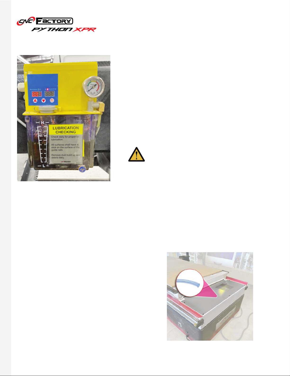
Lubrication
Daily Checks
Maintenance
Our routers come with a fully automated, pressurized lubrication
system for all the liner guides and ball screws. For best results,
use 000 Semi-Fluid Lithium Grease.
All helical racks & drill blocks require manual lubrication with
Klüber Isoflex Topas L32N Special low-temperature grease. As
a rule of thumb, apply 5cc of lubrication after every 40 hours of
operation.
1. Clean the router, wipe off any excess oil, and buff with a dry polishing cloth. This will reduce the chance for
dust build up.
2. Check all liner guides and ball screws. Make sure there is a thin layer of oil on it.
3. Check cutter teeth for chips and dullness.
When lubricating, jog the machine all the way up to
the area without the spoilboard, to avoid damaging it
in case of leaks or drips. Oil on the spoilboard can clog
it and affect material work holding.
AC drain hose inside control cabinet
4. Collets and spindle collet holes must be cleaned
regularly. Ensure that the slots in the collets are free
of sawdust, as it can build up and prevent the collet
from compressing. If the collet or spindle holes
are clogged, the router bit may vibrate or get loose
while cutting. Serious spindle damage or bodily
injury may occur.
5. Check the AC unit drain, make sure it is not twisted
or leaking into the control cabinet under the router
bed.

9
Weekly Checks
Quarterly Checks
Annual Checks
1. Clean grease and dirt off the helical racks. Apply gear
grease on all helical racks.
2. Check the dust collection pipe and brush hood. Clean off
all debris and dust build up.
3. Generally inspect the router for any damage or loose/
worn parts.
4. Empty oil tray under the liner carts.
Conduct a drill block grease check.
Schedule an on-site service with a CNC Factory technician.
Connectivity
The Python has USB, WiFi and ethernet connections. It only requires the internet for virtual/remote access.
Configurations for your router’s connectivity will already be set-up by your technician during installation.
Oil trays
10
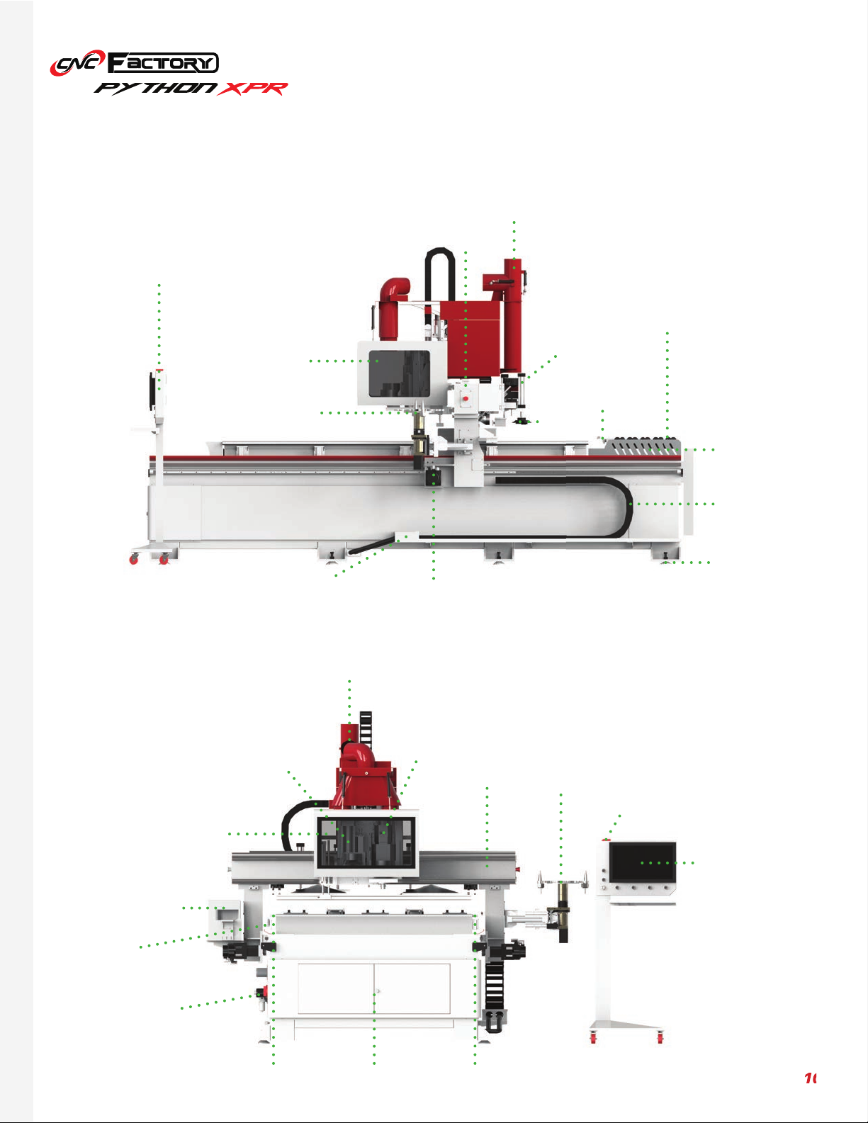
PARTS OF YOUR ROUTER
External Parts
10
Mobile Control
Cart
Machine
Safety Glass
Tool Carousel
Robotic Loading
Arm
Suction
Cup
Rear Pusher
Loading
Wheels
Safety Light
Metal foot
plates
Encased wiring
Servo MotorPlug & Play
Ports
Tool Carousel
Safety Light
21” touchscreen
Spindle
Machine
Safety Glass
Left Rail
Auto Tool
Measuring
Device
Air Pressure
Monitor
Right RailControl Cabinet
Drill block
slot
Gantry
Gantry
Label
Printer
Dust Extraction
Outlet
Dust Extraction
Outlet

11
Mobile Control
Cart
Cooling fans
Robotic Loading
Arm
Safety Light
Auto Tool
Measuring
Device
Main Contact
Switch
Digital vacuum
gauge
E-stop button
Servo Motor
Label Printer
Robotic
Dust Hood
Rear pusher
Rear pusher
Unloading Arm
Dust Extractor
Drill block
slot
Helical Rack
& Pinion Rail
System
2nd vacuum
pump switch
Tool Carousel
Plug & Play
Ports
Air Pressure
Monitor
Air Pressure
Monitor
Vacuum Ports Control Cabinet
Dust Extraction
Outlet
12
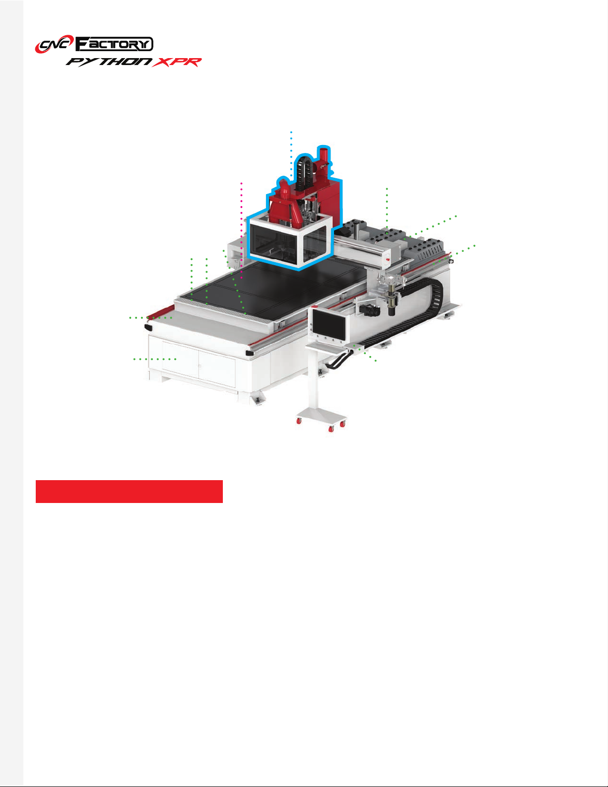
Notable Terminology
Refers to the block of components responsible for cutting that is anchored to the gantry (includes the
spindle, drill block, and dust hood). Whenever there is a mention of machine movement, it refers to this block
(and not to be confused with the router, since the router, after all, is stationary during operations).
Refers to the entire Python XPR, including its controller/control cart.
Router
Machine
Location Pins
Control Cabinet
Unloading conveyor
will be connected
here
Loading table will be
connected here
The “machine”
Dual layer, high
flow phenolic
vacuum table Loading
Wheels
Helical Rack
& Pinion Rail
System
Plug & Play
Ports
13
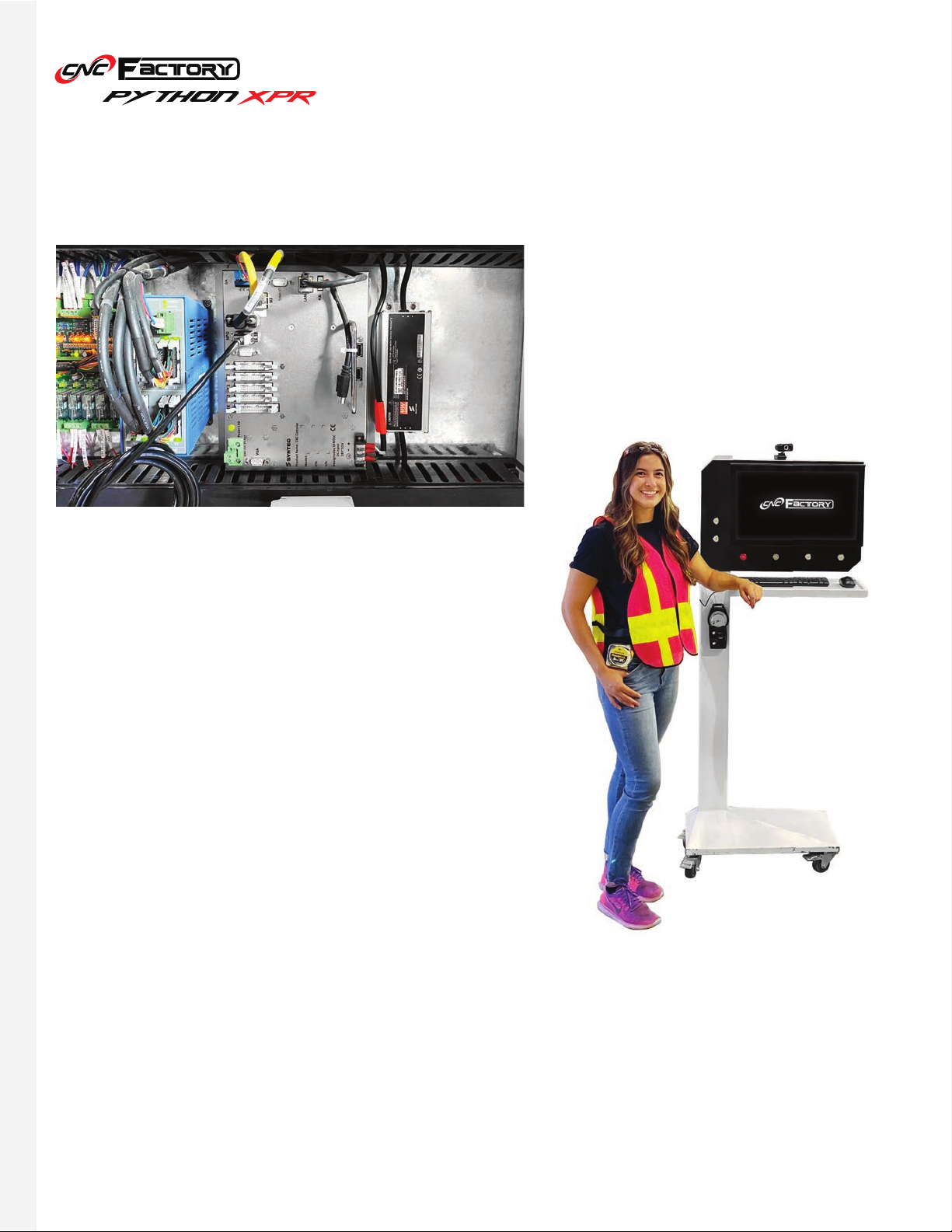
UNDERSTANDING YOUR CONTROLLER
Main Controller vs. Control Cart
(ABOVE) Your actual,
main
controller is located inside your
router cabinet. This is the brain of the machine. You may
operate the router directly by connecting a screen directly
to its VGA port, and importing files through its USB ports. We
recommend this option for advanced technicians.
(RIGHT) This “controller” is a PC with a Windows operating
system, and is sometimes referred to as the “control cart”. An
emulator allows this to behave similarly to your main controller.
We recommend using this in operating the router since it has
a bigger, touchscreen display, as well as the familiar Windows
system that is more user-friendly.
It is important to note the difference since some operations on the Python are typically used only for the main
controller and not for the PC controller/control cart. In this manual, we may also use the term “controller”
interchangeably for both. However, for clarity, when talking about the “main controller”, we are only referring to
the one inside your router.
14
Camera
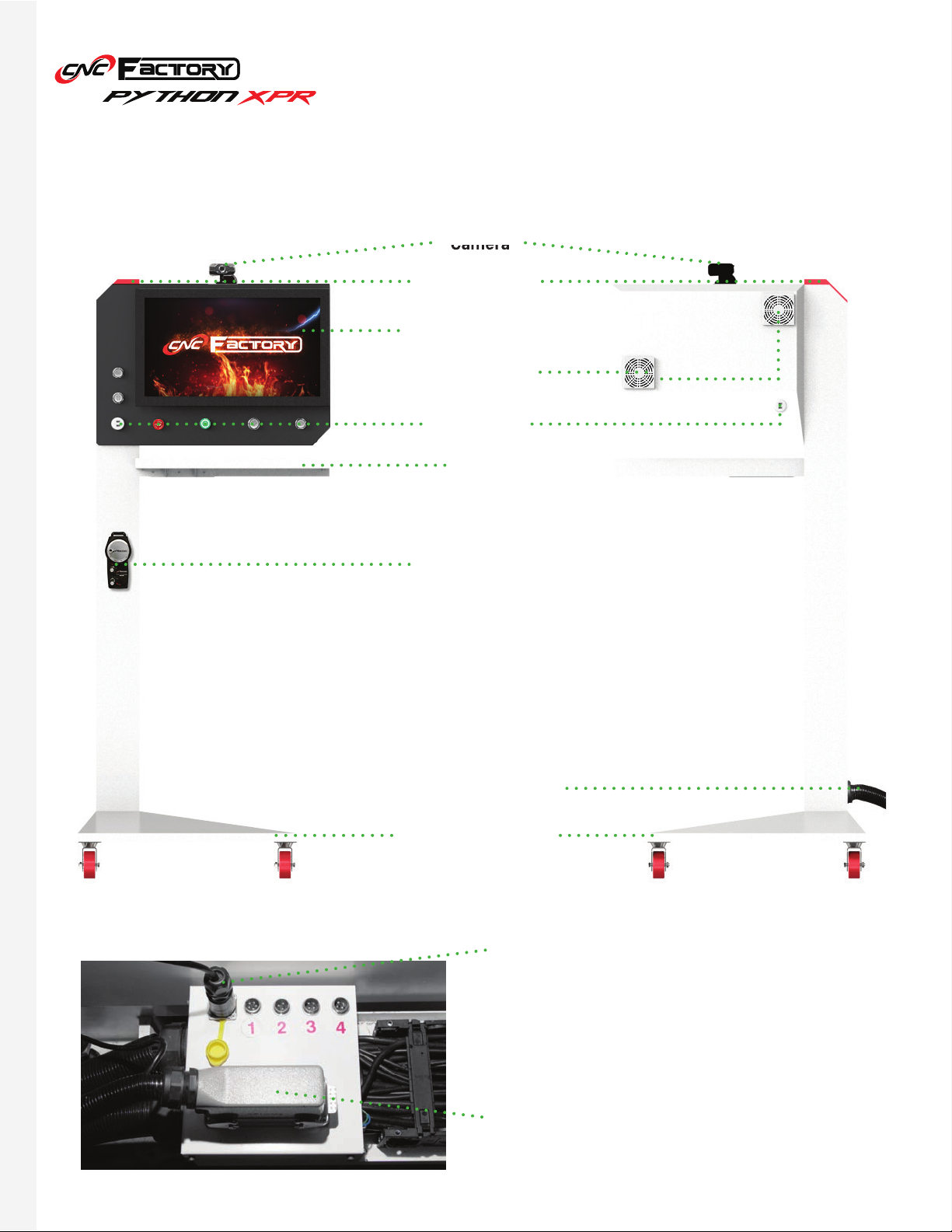
Parts of your Control Cart
Camera
Safety Light
21” Touchscreen
Cooling Fans
MPG Remote
Base with lockable
wheels
USB Ports
Desk
Power & Signal Cord
Powers up the CPU & Screen.
Sends a network signal to the main controller.
1: Loading table power 3: Unloading table data
2: Unloading table power 4: Light curtain
*Soon, a 5th port for loading table data will be available.
Power Cord
Signal Cord

15
Tells the router’s current operating status. For the XPR series, the rear side of the routers have similar safety lights.
• White Light- Static mode: no operation is in progress and the router is ready for a command. In this mode, the
bottom right of the screen will display “Ready”
• Red Light- Alarm mode: there is an operational issue or error. In this mode, the ‘Alarm’ display at the bottom
right of the screen will blink red with “Not Ready” beside it.
• Green Light- Operation mode: operation is in progress. No other command may be executed unless the
current operation is stopped. In this mode, the bottom right of the screen will display “Busy”.
Safety Light
Start Button
Pause Button
Press to start operation. You will have to physically press the button to run a program. This is intentional to prevent
unintended starting from accidental pressing of touchscreen buttons or to prevent people with internet access to
your controller from operating your router remotely.
Pauses the operation. While on pause, your router is still fully powered, motors are still running, the spindle or drill
block are still spinning (although the feed will be zero), and it will not affect all other commands that are queued
up. To resume operation, press the Start button again.
Start Button
Safety Light
Pause Button
USB Ports
Power
Button
Vacuum ButtonsE-Stop
Button
Camera

16
USB Ports
E-Stop Button
Vacuum Buttons
Move clockwise to move on an axis’ positive direction. Move
counterclockwise to move on an axis’ negative direction.
Controls the range of movement (either by 1mm, 10mm, or
100mm increments).
Status lights (1st bar: power indicator, 2nd bar: signal
quality, 3rd bar: low battery).
The MPG remote requires two AA batteries. Remove the protective rubber case
to access the battery terminal (at the back).
Dual ports for importing files or connecting wireless devices (keyboard, mouse).
Instantly shuts everything down including power to the loading and unloading tables (if available). You will need to
restart all files interrupted by this shutdown.
Sends signals to the vacuum box to turn on/off your vacuum pumps. Each button corresponds to a designated
pump (maximum of 2 vacuum pumps).
Controls the axes
• Turning all the way counterclockwise turns the remote
off. Selecting an axis automatically turns it on.
Wireless Handheld MPG Remote
Power Button
Turns the controller and the router on/off. When turning it on, allow a few seconds for the controller to power up.
Once the safety light turns white, it means the main controller is operational and you may click on the Viper icon
on your desktop.
If there are pending alarms, the safety light may light up red after powering on.
Before turning off your router, we recommend shutting down the PC before pressing the power
button. Skipping this step may degrade your PC over time.

17
BASIC OPERATIONS
Turning On the Router
1. Make sure there is no object or person around the router’s motion area to prevent collision.
2. Make sure power and air are connected to the router.
3. Make sure all the E-Stop buttons are released.
4. Rotate the main contact switch clockwise until it clicks in place.
5. Press the green power button on the control cart. The power is on once it turns red.
It may seem counterintuitive, but RED light = controller is ON
GREEN light = controller is OFF
6. After booting into Windows, wait for the Safety Light to turn on, then double click the Python icon on the
desktop and wait for the program to initialize. If you click the Python icon before the safety light comes on,
a Connection Setting window may appear. Just press [F2 IP Connection] to resolve this error.
7. Press and hold the button on the spindle to put the previous tool back into the spindle. Release the button
to lock the tool.
8. Make sure no alarm is pending or flashing. Go to the Utilities screen, click [Spindle warm up].
9. Once the spindle warm up is completed, the machine is ready to use.
Main contact switch at the side of
the router.
Power button on the control cart. Wait for the safety light to turn
white before starting the program.
Python program icon
on the controller
desktop.
Utilities
Screen Tab
Spindle Warm
Up button
Warm up the spindle only
during intitial spindle
setup or when not in use
for a prolonged time.
Otherwise, you can warm
it up once a month.

18
Turning Off the Router
1. On the Utilities screen, switch to Jog Mode by clicking on the [Jog] button.
2. Jog the machine to the tool changer side, press and hold the button on the spindle to release tool and put
that tool in the tool changing station.
3. Jog the Z-axis all the way up.
4. Close the Python software by click the top right X.
5. Shut down Windows.
6. Press the power button on the control cart.
7. Rotate the main contact switch to the OFF position.
8. Disconnect air from the router. Your drill block will drop down after air is disconnected.
As long as you jog the Z-axis all the way up BEFORE turning the machine off, it
should not hit your vacuum table.
Utilities Screen
Tab
Close
Window
Jog button
Z-axis controls

19
Getting Started with your Shortcuts
By default, you will have the following shortcuts pre-installed on your controller’s desktop:
To begin operating, click on the Python icon on your desktop. After loading, you will see the Main Screen.
This is where you upload all your files from your CAD/CAM software. When saving files here, we
recommend saving all files of a single job in 1 folder. We do not recommend saving a folder inside another
folder (or multiple file levels) as this may cause a program error.
The program contains all the controls for
all
functionalities of CNC Factory 5th generation
routers. Further upgrades may be required on your router to perform all these functionalities.
Please contact support@cncfactory.com if you wish to upgrade your router.
• Python icon
• CNC File folder [This PC > Local Disk (C:) > Network > CNC > NcFiles]

20
Main Screen
This is the first screen you see after opening the Python shortcut. It shows real-time information of your machine
location and speed. These will make better sense once you have gone through the rest of the operations in this
manual. There is no action needed on your part for this screen.
This standard CNC display shows the following information:
Feed Speed
Spindle Speed
Axes Info
Function Keys Menu
Date Time Main TabsCurrent File
Main Navigation Belt
Back Button
Press to go back to
the previous page,
or multiple times to
return to the Main
Screen.
Table of contents
Other CNC Industrial Equipment manuals


Popular Industrial Equipment manuals by other brands

Rodix
Rodix FEEDER CUBE FC-40 Plus Series Adjustments and Set Up

ABB
ABB HT611078 Operation manual

Tyco Electronics
Tyco Electronics DT-3000 Customer's manual

SAMCHULLY
SAMCHULLY TS Series instruction manual

Salda
Salda AVS Series Mounting and installation instructions

ABB
ABB PVI-6000-TL-OUTD-W Quick installation guide


