Midea TC051K6BW-S User manual

SAVE THESE INSTRUCTIONS CAREFULLY
Read these instructions carefully before using your
microwave oven, and keep it carefully.
If you follow the instructions, your oven will provide you with
many years of good service.
Model:TC051K6BW-S

PRECAUTIONS TO AVOID POSSIBLE
EXPOSURE TO EXCESSIVE MICROWAVE
ENERGY
(a) Do not attempt to operate this oven with the door open since open door
operation can result in harmful exposure to microwave energy.
It is important not to defeat or tamper with the safety interlocks.
(b) Do not place any object between the oven front face and the door or allows soil
or cleaner residue to accumulate on sealing surfaces.
(c) Do not operate the oven if it is damaged. It is particularly important that
the oven door close properly and that there is no damage to the:
(1) DOOR (bent)
(2) HINGES AND LATCHES (broken or loosened)
(3) DOOR SEALS AND SEALING SURFACES
(d) The oven should not be adjusted or repaired by anyone except properly
qualified service personnel.
Specifications
Model: TC051K6BW-S
120V~ 60Hz
1650W
1000W
1600W
Rated Voltage:
Rated Input Power (Microwave):
Rated Output Power (Microwave):
Rated Output Power (Convection):
2

1. Read all instructions before using the appliance.
2. Read and follow the specific: " PRECAUTIONS TO AVOID POSSIBLE EXPOSURE TO
EXCESSIVE MICROWAVE ENERGY" found on page 2.
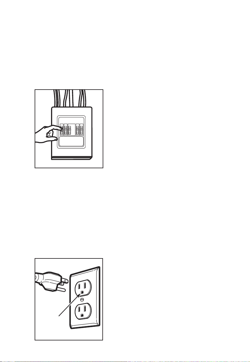
3. This appliance must be grounded. Connect only to properly grounded outlet. See
" GROUNDING INSTRUCTIONS" found on page 5.
4. Install or locate this appliance only in accordance with the provided installation
instructions.
5. Some products such as whole eggs and sealed containers - for example, closed glass
jars - are able to explode and should not be heated in this oven.
6. Use this appliance only for its intended use as described in the manual. Do not use
corrosive chemicals or vapors in this appliance. This type of oven is specifically
designed to heat, cook or dry food. It is not designed for industrial or laboratory use.
7. As with any appliance, close supervision is necessary when used by children.
8. Do not operate this appliance if it has a damaged cord or plug, if it is not working
properly, or if it has been damaged or dropped.
9. This appliance should be serviced only by qualified service personnel. Contact nearest
authorized service facility for examination, repair, or adjustment.
10. Do not cover or block any openings on the appliance.
11. Do not store this appliance outdoors. Do not use this product near water - for example,
near a kitchen sink, in a wet basement, near a swimming pool, or similar location.
12. Do not immerse cord or plug in water.
13. Keep cord away from heated surface.
14. Do not let cord hang over edge of table or counter.
15. When cleaning surfaces of door and oven that comes together on closing the door,
use only mild, nonabrasive soaps, or detergent applied with a sponge or soft cloth.
16. To reduce the risk of fire in the oven cavity:
1). Do not overcook food. Carefully attend appliance when paper, plastic, or other
combustible materials are placed inside the oven to facilitate cooking.
2). Remove wire twist-ties from paper or plastic bag before placing bag in oven.
3). If material inside of the oven ignite, keep oven door closed, turn oven off, and
disconnect the power cord, or shut off power at the fuse or circuit breaker panel.
4). Do not use the cavity for storage purposes. Do not leave paper products, cooking
utensils, or food in the cavity when not in use.
WARNING - To reduce the risk of burns, electric shock, fire, injury to persons or exposure
to excessive microwave energy:
IMPORTANT SAFETY INSTRUCTIONS
When using electrical appliances basic safety precautions should be followed, including
the following:
3

17. Liquids, such as water, coffee, or tea are able to be overheated beyond the boiling
point without appearing to be boiling. Visible bubbling or boiling when the container is
removed from the microwave oven is not always present.
THIS COULD RESULT IN VERY HOT LIQUID SUDDENLY BOILING OVER WHEN
THE CONTAINER IS DISTURBED OR A UTENSIL IS INSERTED INTO THE LIQUID.
To reduce the risk of injury to persons:
1) Do not overheat the liquid.
2) Stir the liquid both before and halfway through heating it.
3) Do not use straight-sided containers with narrow necks.
4) After heating, allow the container to stand in the microwave oven for a short time
before removing the container.
5) Use extreme care when inserting a spoon or other utensil into the container.
18. Oversized food or oversized metal utensils should not be inserted in a microwave/
toaster oven as they may create a fire or risk of electric shock.
19. Do not clean with metal scouring pads. Pieces can burn off the pad and touch
electrical parts involving a risk of electric shock.
20. Do not use paper products when appliance is operated in the toaster mode.
21. Do not store any materials, other than manufacturer's recommended accessories, in
this oven when not in use.
22. Do not cover racks or any other part of the oven with metal foil. This will cause over-
heating of the oven.
23. Clean Ventilation Hoods Frequently - Grease should not be allowed to accumulate on
hood or filter.
24. When flaming foods under the hood, turn the fan on.
25. Use care when cleaning the vent-hood filter. Corrosive cleaning agents, such as lye-
based oven cleaners, may damage the filter.
26. Suitable for use above both gas and electric cooking equipment.
SAVE THESE INSTRUCTIONS
4
This device complies with Part 18 of the FCC Rules

GROUNDING INSTRUCTIONS
This appliance must be grounded. In the event of an electrical short circuit, grounding
reduces the risk of electric shock by providing an escape wire for the electric current.
This appliance is equipped with a cord having a grounding wire with a grounding plug.
The plug must be plugged into an outlet that is properly installed and grounded.
WARNING - Improper use of the grounding can result in a risk of electric shock.
Consult a qualified electrician or serviceman if the grounding instructions are not
completely understood, or if doubt exists as to whether the appliance is properly
grounded. If it is necessary to use an extension cord, use only a 3-wire extension
cord that has a 3-blade grounded plug, and 3-slot receptacle that will accept the
plug on the appliance. The marked rating of the extension cord shall be equal to or
greater than the electrical rating of the appliance.
DANGER - Electric Shock Hazard
Touching some of the internal components can cause serious personal injury or death.
Do not disassemble this appliance.
WARNING - Electric Shock Hazard
Improper use of the grounding can result in electric shock. Do not plug into an outlet
until appliance is properly installed and grounded.
1. A short power-supply cord is provided to reduce the risks resulting from becoming
entangled in or tripping over a longer cord.
2. Longer cord sets or extension cords are available and may be used if care is
exercised in their use.
3. If a long cord or extension cord is used:
1) The marked electrical rating of the cord set or extension cord should be at least
as great as the electrical rating of the appliance.
2) The extension cord must be a grounding-type 3-wire cord.
3) The longer cord should be arranged so that it will not drape over the counter top
or tabletop where it can be pulled on by children or tripped over unintentionally.
5

1. Operation of the microwave oven may cause interference to your radio, TV or similar
equipment.
2. When there is interference, it may be reduced or eliminated by taking the following
measures:
1) Clean door and sealing surface of the oven
2) Reorient the receiving antenna of radio or television.
3) Relocate the microwave oven with respect to the receiver.
4) Move the microwave oven away from the receiver.
5) Plug the microwave oven into a different outlet so that microwave oven and receiver
are on different branch circuits.
RADIO INTERFERENCE
6
FCC RF Exposure Requirements
This device complies with FCC RF radiation exposure limits set forth for an uncontrolled
enviroment. The antenna(s) used for this transmitter must not be co-located or operating
in conjunction with any other antenna or transmitter and must be installed to provide a
separation distance of at least 20cm from all persons.

UTENSILS
CAUTION - Personal Injury Hazard
Tightly-closed utensils could explode. Closed containers should be opened and plastic
pouches should be pierced before cooking.
See the instructions on "Materials you can use in microwave oven or to be avoided in
microwave oven."
There may be certain non-metallic utensils that are not safe to use for microwaving.
If in doubt, you can test the utensil in question following the procedure below.
Utensil Test:
1. Fill a microwave-safe container with 1 cup of cold water (250ml) along with the
utensil in question.
2. Cook on maximum power for 1 minute.
3. Carefully feel the utensil. If the empty utensil is warm, do not use it for microwave
cooking.
4. Do not exceed 1 minute cooking time.
7

8
INSTALLATION INSTRUCTIONS
IMPORTANT SAFETY INSTRUCTIONS
This product requires a three-prong grounded outlet.
The installer must perform a ground continuity check on the power outlet box before
beginning the installation to ensure that the outlet box is properly grounded.
If not properly grounded, or if the outlet box does not meet electrical requirements noted
(under ELECTRICAL REQUIREMENTS), a qualified electrician should be employed to
correct any deficiencies.
CAUTION: For personal safety, the mounting surface must be capable of supporting the
cabinet load, in addition to the added weight of this 63–85 pound (28.5–38.5 kg) product,
plus additional oven loads of up to 50 pounds (22.7 kg) or a total weight of 113–135
pounds (51.3–61.2 kg).
CAUTION: For personal safety, this product cannot be installed in cabinet arrangements
such as an island or a peninsula. It must be mounted to BOTH a top cabinet AND a wall.
NOTE: For easier installation and personal safety, it is recommended that two people
install this product.
IMPORTANT – PLEASE READ CAREFULLY. FOR PERSONAL SAFETY, THIS
APPLIANCE MUST BE PROPERLY GROUNDED TO AVOID SEVERE OR FATAL
SHOCK.
CAUTION: For personal safety,
remove house fuse or open
circuit breaker before beginning
installation to avoid severe
or fatal shock injury.
The power cord of this appliance
is equipped with a three-prong
(grounding) plug which mates with
a standard three-prong (grounding)
wall receptacle to minimize the
possibility of electric shock hazard
from this appliance.
Ensure proper
ground exists
before use

9
You should have the wall receptacle and circuit checked by a qualified electrician to
make sure the receptacle is properly grounded.
Product rating is 120 volts AC, 60 Hertz, 15 amps and 1.6 kilowatts. This product must be
connected to a seperate and dedicated supply circuit of the proper voltage and frequency.
Wire size must conform to the requirements of the National Electrical Code or the prevailing
local code for this kilowatt rating.
The power supply cord and plug should be brought to a seperate and dedicated 15- to
20- ampere branch circuit single grounded outlet. The outlet box should be located in the
cabinet above the microwave oven.
The outler box and supply circuit should be installed by a qualifed electrician and conform
to the National Electrical Code or the prevailing local code.
Where a standard two-prong wall receptacle is encountered, it is very important to have it
replaced with a properly grounded three-prong wall receptacle, installed by a qualified
electrician.
DO NOT, UNDER ANY CIRCUMSTANCES, CUT, DEFORM OR REMOVE ANY OF THE
PRONGS FROM THE POWER CORD. DO NOT USE WITH AN EXTENSION CORD.
ELECTRICAL REQUIREMENTS
• If the unit is damaged in shipment, return the unit to the store in which it was bought for
repair or replacement.
• If the unit is damaged by the customer,repair or replacement is the responsibility of the
customer.
• If the unit is damaged by the installer (if other than the customer), repair or replacement
must be made by arrangement between customer and installer.
DAMAGE—SHIPMENT/ INSTALLATION
PARTS INCLUDED
HARDWARE PACKET
PART QUANTITY
Nylon Grommet
(for metal cabinets)
Wood Screws
(1/4“ x 2“) 2
2
3
1
Toggle Bolts
(and wing nuts)
3/16 “( x 3“)
Self-Aligning
Machine Screws
1/(4“-28 1x/4 “3)
You will find the installation hardware contained in a packet with the unit. Check to make
sure you have all these parts.
NOTE: Some extra parts are included.

10
PARTS INCLUDED (CONT.)
ADDITIONAL PARTS
PART
INSTALLATION
INSTRUCTIONS
QUANTITY
Top Cabinet
Template
RearWall
Template
Installation
Instructions
Separately
Packed Grease
Filters
1
1
1
Exhaust adaptor 1
Glass Tray 1
Turntabl Ring 1
Convection
wire rack
For some models
For some models
1
Shelf 1
2

11
• Tape measure
• Hole saw
• Stud finder or hammer
• Level
• Duct and masking tape
• Scissors
• The space between the cabinets must be 30" (76.2 cm) wide and free of obstructions.
• If you are going to vent your microwave oven to the outside, see Hood Exhaust Section
for exhaust duct preparation
• When installing the microwave oven beneath smooth, flat cabinets, be careful to follow the
instructions on the top cabinet template for power cord clearance.
• As a guide to installation, see page 25 for Mounting Template Information.
• If the cabinet depth, including the cabinet doors, is more than 13”, then the unit must be
spaced out from wall using adequate materials supporting 150 lbs to allow proper top
vent air exhaust/intake.
• #1 Phillips screw driver
• Electric drill
• 3/16”, 1/2”, 5/8” drill bit
• Filler wood blocks for recessed bottom cabinets
• Tin snips
Tools you will need:
Mounting Space
66"
(167.6 cm)
or more from the
floor to the top of
the microwave
¼" Min
13" Max
(33 cm)
16 ½"
(41.9 cm)
Backsplash
30
30
(76.2 cm)
min.
Cabinet
(5.1 cm)
2"
Cabinet
Clearance
(33 cm)
13" MAX.
"(76.2 cm)
"

12
1. PLACEMENT OF THE MOUNTING 1 PLATE
A. REMOVING THE MICROWAVE OVEN FROM THE CARTON/ REMOVING THE
MOUNTING PLATE
1. Remove the installation instructions,use and care, exhaust adapter, turntable ring,
shelf, filters, glass tray and the small hardwarebag. Do not remove the Styrofoam
protecting the front of the oven.
please note: Do Not Remove plastic plug protective cover until just before hanging the
unit.
Keep the unit at least 8 inches away from the counter top edge to preven t dropping
becau se of the heavy doo. r
2. Fold back all 4 carton flapsfully against carton sides.Then carefully roll the oven and
carton over on to the top side.The oven should be resting in the Styrofoam.
Filters and Turntable
Ring below glass tray
Exhaust Adapter
Small Hardware Bag
Glass Tray
Shelf ( For some
models)
Carton
Styrofoam

13
3. Pull the carton up and off the oven.
4. Cut the middle of the out erprotective plastic bag to remove the mounting plate.
5. Remove the screws from each end of the mounting plate. This plate will be used as
the rear wall template and for mounting. Reinstall the screws into the holes where
they were removed.
1. Find the studs,using one oft he following methods:
A. Stud find er–amagneticdevice which locatesnails.
B. Use ahammerto taplightly across the mounting surface to find asolid sound.
This willindicateastudlocation.
2. After locating the stud(s),find the centerby probing the wall with as mallnail to find the
edges of the stud.Then placea mark half way between the edges.
The center of any adjacent studs should be16 (40.6cm) or 24 (61cm) from this mark.
3. Draw aline down the center of the studs.
THEMICROWAVEMUST BE CONNECTED TO AT LEAST ONEWALL STUD.
Screws Screws
Mounting Plate
B. FINDING THE WALL STUDS
Wall
Studs
Center

14
C. DETERMINING WALL PLATE LOCATION UNDER YOUR CABIN ET
Plate position-beneath flat bottom cabinet.
Plate position-beneath recessed bottom cabinet with front overhang
²
Atleast30
″
C
3/8"TOEDGE
NOTE:ITISVERYIMPORTANTTO
READANDFOLLOWTHEDIRECTIONS
INTHEINSTALLATIONINSTRUCTIONS
BEFOREPROCEEDINGWITH THIS
REARWALL TEMPLATE.
ThisRearWall Template serves to positionthe bottom
mountingplateandto locate the horizontalexhaust
outlet.
1.Usea level to check that thetemplate is positioned
accurately.
2.Locate and mark at leastonestudonthe left or
right sideofthecenterline.
Itis important to use atleast one wood
screwmountedfirmly in astud to supporttheweight
ofthemicrowave.Marktwo additional, evenly spaced
locationsfor the suppliedtogglebolts.
3.Drillholesin themarked locations.Where there is
astud,drill a 3/16" holeforwoodscrews. For holes
that donot lineupwith astud, drill 5/8" holesfor
togglebolts.
DONOTINSTALLTHE MOUNTING PLATE
ATTHISTIME.
4.Removethe templatefromtherearwall.
5.ReviewtheInstallation Instruction bookforyour
installation situation.
Locateandmarkholes toalign with holes in the
mountingplate.
IMPORTANT:
LOCATEATLEAST ONESTUD ON EITHERSIDE OF
THECENTERLINE.
MARKTHELOCATION FOR 2 ADDITIONAL, EVENLY
SPACEDTOGGLEBOLTS IN THE MOUNTINGPLATE
AREA.
Locateand markholestoalign with holes in the
mountingplate.
IMPORTANT:
LOCATEAT LEAST ONESTUDONEITHER SIDEOF
THECENTERLINE.
MARKTHELOCATIONFOR 2ADDITIONAL, EVENLY
SPACEDTOGGLE BOLTSIN THE MOUNTING PLATE
AREA.
Trimthe rearwalltemplate along the dotted line.
Trimthe rear walltemplate alongthedottedline.
12"
4"
Darlevueltaa lahojaparaconsultar la
versiónenEspañol.
16-1/2
1/4"
Minimum
clearance
Draw a vertical line on the wall at the
center of the 30″ wide space.
Tape the Rear Wall Template onto the wall
matching the centerline and touching the
bottom of the cabinet.
to Cooktop
C
3/8"TOEDGE
NOTE:ITISVERYIMPORTANTTO
READANDFOLLOWTHEDIRECTIONS
INTHEINSTALLATIONINSTRUCTIONS
BEFOREPROCEEDINGWITHTHIS
REARWALLTEMPLATE.
ThisRearWallTemplateservestoposition the bottom
mountingplateandtolocatethehorizontalexhaust
outlet.
1.Usealeveltocheckthatthetemplateis positioned
accurately.
2.Locateandmarkatleast onestudon theleftor
rightsideofthecenterline.
Itisimportanttouseat leastonewood
screwmountedfirmlyin a studtosupportthe weight
ofthemicrowave.Marktwoadditional,evenly spaced
locationsforthesuppliedtogglebolts.
3.Drillholesinthe markedlocations. Where thereis
astud,drilla3/16"holeforwoodscrews.Forholes
thatdonotlineupwithastud,drill5/8"holesfor
togglebolts.
DONOTINSTALLTHEMOUNTINGPLATE
ATTHISTIME.
4.Removethetemplatefrom the rear wall.
5.ReviewtheInstallationInstructionbookforyour
installationsituation.
Locateandmarkholestoalignwith holes in the
mountingplate.
IMPORTANT:
LOCATEATLEASTONESTUD ON EITHER SIDEOF
THECENTERLINE.
MARKTHELOCATIONFOR2ADDITIONAL,EVENLY
SPACEDTOGGLEBOLTSINTHE MOUNTING PLATE
AREA.
Locateandmarkholes to align with holes inthe
mountingplate.
IMPORTANT:
LOCATEATLEASTONESTUD ON EITHERSIDE OF
THECENTERLINE.
MARKTHELOCATIONFOR2 ADDITIONAL,EVENLY
SPACEDTOGGLEBOLTSINTHEMOUNTINGPLATE
AREA.
Trimtherearwalltemplate along thedottedline.
Trimtherearwall template alongthedottedline.
12"
4"
Darlevueltaalahoja para consultarla
versiónenEspañol.
C
L
3/8"TOEDGE
NOTE:ITIS VERY IMPORTANT TO
READANDFOLLOW THE DIRECTIONS
INTHEINSTALLATIONINSTRUCTIONS
BEFOREPROCEEDING WITH THIS
REARWALL TEMPLATE.
ThisRearWall Template servesto positionthe bottom
mountingplateand to locatethe horizontal exhaust
outlet.
1.Usealevel to check thatthetemplate is positioned
accurately.
2.Locate andmarkat least onestud on the left or
right sideofthe centerline.
Itis important touse at least one wood
screwmountedfirmly in a studto supporttheweight
ofthemicrowave.Marktwoadditional, evenlyspaced
locationsforthesuppliedtoggle bolts.
3.Drill holesin the markedlocations. Where thereis
a stud, drill a3/16"hole forwood screws.Forholes
that do not lineup with a stud, drill 5/8" holes for
toggle bolts.
DONOTINSTALLTHE MOUNTINGPLATE
ATTHISTIME.
4.Removethetemplate from the rear wall.
5.Reviewthe InstallationInstructionbook foryour
installation situation.
Locateandmark holes to align withholes in the
mountingplate.
IMPORTANT:
LOCATEAT LEAST ONE STUD ON EITHER SIDE OF
THECENTERLINE.
MARKTHE LOCATIONFOR 2 ADDITIONAL,EVENLY
SPACEDTOGGLE BOLTS INTHE MOUNTING PLATE
AREA.
Locateandmark holes to align withholes in the
mountingplate.
IMPORTANT:
LOCATEAT LEAST ONE STUD ON EITHER SIDEOF
THECENTERLINE.
MARKTHE LOCATIONFOR2ADDITIONAL, EVENLY
SPACEDTOGGLEBOLTS INTHE MOUNTINGPLATE
AREA.
Trimtherear wall template along the dotted line.
Trimtherear wall template along thedotted line.
12"
4"
Darlevuelta a la hoja paraconsultarla
versiónenEspañol.
30
1/4"
Minimum
clearance
Draw a line on the
back wall equal to the
depth of the front
overhang.
1/4"
Minimum
clearance

15
Draw a vertical line on the wall at the center of the 30″ space.
Tape the Rear Wall Template onto the wall matching the centerline
and touching the bottom cabinet frame.
to Cooktop
C
3/8"TO EDGE
NOTE:ITIS VERYIMPORTANT TO
READANDFOLLOW THE DIRECTIONS
INTHE INSTALLATION INSTRUCTIONS
BEFOREPROCEEDINGWITHTHIS
REARWALL TEMPLATE.
ThisRearWallTemplate serves to position the bottom
mountingplateandto locate thehorizontal exhaust
outlet.
1.Usealevel to check thatthetemplate is positioned
accurately.
2.Locateandmarkatleast one studon the left or
rightsideofthecenterline.
Itis importantto use at leastonewood
screwmountedfirmly in a stud tosupport the weight
ofthemicrowave.Mark two additional, evenlyspaced
locationsforthesupplied toggle bolts.
3.Drill holes in themarked locations. Wherethere is
a stud,drill a 3/16" hole for wood screws. Forholes
thatdo not line up witha stud,drill 5/8" holes for
toggle bolts.
DONOTINSTALLTHE MOUNTING PLATE
ATTHIS TIME.
4.Removethe template fromtherearwall.
5.Reviewthe InstallationInstructionbook for your
installationsituation.
Locateand mark holes to align with holes in the
mountingplate.
IMPORTANT:
LOCATEATLEAST ONE STUD ON EITHER SIDE OF
THECENTERLINE.
MARKTHELOCATION FOR 2 ADDITIONAL, EVENLY
SPACEDTOGGLE BOLTSIN THEMOUNTING PLATE
AREA.
Locateandmark holes to align with holes in the
mountingplate.
IMPORTANT:
LOCATEATLEASTONE STUD ON EITHER SIDE OF
THECENTERLINE.
MARKTHE LOCATION FOR2ADDITIONAL,EVENLY
SPACEDTOGGLE BOLTS IN THE MOUNTING PLATE
AREA.
Trimthe rear wall template along thedottedline.
Trimtherear wall template alongthe dotted line.
12"
4"
Darlevueltaala hoja para consultar la
versiónenEspañol.
30
1/4"
Minimum
clearance
Plate position-beneath framed recessed cabinet bottom
Your cabinets may have decorative trim that interferes with the microwave installation.
Remove the decorative trim to install the microwave properly and to make it level.
Use a level to make sure the cabinet bottom is level.
If the cabinets have a front overhang only, with no back or side frame, install the mounting
plate down the same distance as the front overhang depth.
This will keep the microwave level.
1. Measure the inside depth of the front overhang.
2. Draw a horizontal line on the back wall an equal distance below the cabinet bottom as
the inside depth of the front overhang.
3. For this type of installation with front overhang only, align the mounting tabs with this
horizontal line, not touching the cabinet bottom as described in Step D.
THE MICROWAVE MUST BE LEVEL.

16
D. ALIGNING THE WALL PLATE
Area E Hole A
Hole B
Centerline
notches Draw a Vertical Line
on Wall from Center
of Top Cabinet
Draw a horizontal line on wall at the
bottom of “Rear Wall Template”.
Horizontal Line
Horizontal Line
CL
3/8" TO EDGE
NOTE: IT IS VERY IMPORTANT TO
READ AND FOLLOW THE DIRECTIONS
IN THE INSTALLATION INSTRUCTIONS
BEFORE PROCEEDING WITH THIS
REAR WALL TEMPLATE.
This Rear Wall Template serves to position the bottom
mounting plate and to locate the horizontal exhaust
outlet.
1. Use a level to check that the template is positioned
accurately.
2. Locate and mark at least one stud on the left or
right side of the centerline.
It is important to use at least one wood
screw mounted firmly in a stud to support the weight
of the microwave. Mark two additional, evenly spaced
locations for the supplied toggle bolts.
3. Drill holes in the marked locations. Where there is
a stud, drill a 3/16" hole for wood screws. For holes
that do not line up with a stud, drill 5/8" holes for
toggle bolts.
DO NOT INSTALL THE MOUNTING PLATE
AT THIS TIME.
4. Remove the template from the rear wall.
5. Review the Installation Instruction book for your
installation situation.
Locate and mark holes to align with holes in the
mounting plate.
IMPORTANT:
LOCATE AT LEAST ONE STUD ON EITHER SIDE OF
THE CENTERLINE.
MARK THE LOCATION FOR 2 ADDITIONAL, EVENLY
SPACED TOGGLE BOLTS IN THE MOUNTING PLATE
AREA.
Locate and mark holes to align with holes in the
mounting plate.
IMPORTANT:
LOCATE AT LEAST ONE STUD ON EITHER SIDE OF
THE CENTERLINE.
MARK THE LOCATION FOR 2 ADDITIONAL, EVENLY
SPACED TOGGLE BOLTS IN THE MOUNTING PLATE
AREA.
Trim the rear wall template along the dotted line.
12"
4"
Darle vuelta a la hoja para consultar la
versión en Español.
CAUTION: Wear gloves during installation.
NOTE: Holes A and B are inside area E. If neither of Holes A and B are not in a stud, find
a stud somewhere in area E and draw a circle to line up with the stud. It is important to
have at least one wood screw mounted firmly in a stud to support the weight of the
microwave. Set the mounting plate aside.
NOTE: DO NOT MOUNT THE PLATE AT THIS TIME.
1. Draw a vertical line on the wall at the center of the 30" wide space.
2. Draw a horizontal line on the wall at the bottom of “Rear Wall Template”.
3. Find a wall stud in area "E" of mounting plate Refer to section 1B. Finding the wall studs.
4. For attaching the mounting plate into stud drill a 3/16" hole into wood stud. Drill a 5/8"
hole for toggle bolt in 1 other location (Hole A or Hole B)

17
2. INSTALLATION TYPES (Choose A, B or C)
This microwave oven is designed for adaptation to the following three types of ventilation:
A. Recirculating (Non-Vented Ductless)
B. Outside Back Exhaust (Horizontal Duct)
C. Outside Top Exhaust (Vertical Duct)
NOTE: This microwave is shipped assembled for Recirculating. Select thetype of
ventilation required for your installation and proceed to that section.
A. RECIRCULATING (NON-VENTED DUCTLESS)
B. OUTSIDE BACK EXHAUST (HORIZONTAL DUCT)
Models are shipped for recirculating exhaust.
Some models have a disposable charcoal filter installed to help remove smoke and odors.
See page 10
See page 16
Adaptor Must Be
Moved to the Back for
Outside Back Exhaust

18
Adaptor in Place for
Outside Top Exhaust
C. OUTSIDE TOP EXHAUST (VERTICAL DUCT)
A. RECIRCULATING (Non-Vented Ductless)
INSTALLATION OVERVIEW
A1. Attach Mounting Plate to Wall
A2. Prepare Top Cabinet
A3. Check Blower Plate
A4. Mount the Microwave Oven
A5. Install or change Charcoal Filter
IMPORTANT NOTES:
• Make sure the screws for the blower motor and blower plate are securely tightened when
they are reinstalled.
This will help to prevent excessive vibration.
• Make sure the motor wiring has been properly routed and secured, and that the wires are
not pinched.
NOTE: Read the pages 14-15 only if you plan to vent your exhaust to the outside.
If you plan to recirculate the air back into the room, proceed to page 10.
See page 20
3/8"TO EDGE
NOTE:IT IS VERY IMPORTANT TO
READAND FOLLOWTHE DIRECTIONS
INTHE INSTALLATION INSTRUCTIONS
BEFOREPROCEEDING WITH THIS
REARWALL TEMPLATE.
ThisRear Wall Template servesto position thebottom
mountingplate and to locate the horizontal exhaust
outlet.
1.Use a level tocheckthat the template is positioned
accurately.
2.Locate and markatleast one stud on the left or
rightsideofthe centerline.
Itisimportant to use at leastone wood
screwmountedfirmlyin a stud to support the weight
ofthe microwave.Marktwoadditional, evenly spaced
locationsfor thesupplied toggle bolts.
3.Drill holes inthemarked locations. Wherethere is
astud,drill a 3/16" hole for woodscrews. For holes
thatdo not line up with a stud, drill 5/8"holes for
togglebolts.
DONOTINSTALL THEMOUNTING PLATE
ATTHISTIME.
4.Remove the template from the rear wall.
5.Revie ht
weInstallation Instruction book foryour
installationsituation.
Locateand mark holes toalign with holes in the
mountingplate.
IMPORTANT:
LOCATEATLEAST ONESTUD ON EITHERSIDEOF
THECENTERLINE.
MARKTHELOCATION FOR 2 ADDITIONAL, EVENLY
SPACEDTOGGLE BOLTS INTHE MOUNTING PLATE
AREA.
Locateand mark holes to align with holes inthe
.
e
t
a
l
p
gn
i
tnu
o
m
IMPORTANT:
LOCATEATLEAST ONESTUD ON EITHER SIDE OF
THECENTERLINE.
MARKTHE LOCATIONFOR2 ADDITIONAL, EVENLY
SPACEDTOGGLEBOLTS IN THE MOUNTING PLATE
AREA.
Trimthe rear wall template along the dottedline.
Trimthe rear wall template along the dotted line.
12"
4"
Darlevuelta ala hoja para consultar la
versiónenEspañol.

Cabinet
Cabinet
(33 cm)
13" MAX.
19
A1. ATTACH THE MOUNTING PLATE TO THE WALL
NOTE: If the cabinet depth including the cabinet doors is more than 13'' then the unit
must be spaced out from wall using adequate materials supporting 150 Ibs to allow proper
top vent air exhaust/intake.
1. Remove the toggle wings from the bolts.
2. Insert the bolts into the mounting plate through the holes designated to go into drywall
and reattach the toggle wings to 3⁄4″(19 mm) onto each bolt.
To use toggle bolts:
Attach the plate to the wall using toggle bolts.
At least one wood screw must be used to attach
the plate to a wall stud.
Wall
Mounting
Plate
Spacing for Toggles
More Than Wall
Thickness
Bolt End
Toggle
Bolt
Toggle Wings

20
3. Place the mounting plate against the wall and insert the toggle wings into the holes in
the wall to mount the plate.
A2. USE TOP CABINET TEMPLATE FOR PREPARATION OF TOP CABINET
A3. CHECK BLOWER PLATE
• Place the microwave in its upright position, with the top of the unit facing up.
• Check to see that the blower plate is correctly installed on the unit.
You need to drill holes for the top support screws and a hole large enough for the power
cord to fit through.
• Read the instructions on the TOP CABINET TEMPLATE.
• Tape it underneath the top cabinet.
NOTE: Adjust top template accordingly if the microwave is being spaced out from the wall
due to cabinet depth (including cabinet doors) of more than 13".
• Drill the holes, following the instructions on the TOP CABINET TEMPLATE.
CAUTION: Wear safety goggles when drilling holes in the cabinet bottom.
NOTE: Before tightening toggle bolts and wood screw, make sure the bott m of the
mounting plate touch the bottom of the cabinet when pushed flush against the wall and
that the plate is properly centered under the cabinet.
CAUTION: Be careful to avoid pinching fingers between the back of the mounting plate
and the wall.
4. Tighten all bolts. Pull the plate away from the wall to help tighten the bolts.
Blower Plate
Table of contents
Other Midea Microwave Oven manuals

Midea
Midea XM925AYY-PV4 User manual

Midea
Midea EM234A PV Series User manual

Midea
Midea EM044K6DM-P User manual

Midea
Midea MMO-MM920MZ BK User manual

Midea
Midea EM145A2HG User manual

Midea
Midea 315530 User manual

Midea
Midea MMG2022JS User manual

Midea
Midea AG820AKB User manual

Midea
Midea MM720C2AT User manual

Midea
Midea AM823ABV User manual

Midea
Midea AS823EBV-S00E(R) User manual

Midea
Midea EG823A4X User manual

Midea
Midea AW925EBL-S10E User manual

Midea
Midea EM923A2CI-PS User manual

Midea
Midea E820NY User manual

Midea
Midea EM131MYY-PV5 User manual

Midea
Midea AG823ABX User manual

Midea
Midea 1025F1A User manual

Midea
Midea AG823E3C-P00E User manual

Midea
Midea MPD8120 User manual