Midian Electronics TTE-7 User manual

TTE-7
DTMF Dialing Encoder
Manual Revision: 2010-04-16
Covers Hardware Revision:
TTE-7: 7163A & Higher
1

SPECIFICATIONS
Operating Voltage 6.5-24 VDC
Operating Current 3 mA
PTT Output Current 250 mA
Audio Output Level 0-750 mV(rms)
Audio Output Impedance 1 K or 50 K
Twist 0-3 dB
Max Tone Distortion 2%
Interkey Time (Auto PTT) 2 seconds
Adjustment Pots 1 Turn
Operating Temperature -30° to +60°C
Dimensions with Bezel Frame (standard) 2.4" x 1.9" x 0.4"
Dimensions without Bezel Frame 2.0” x 1.5" x 0.25"
GENERAL INFORMATION
The TTE-7 is a 12-digit DTMF dial encoder with snap-dome keypad in a mountable bezel frame. The TTE-7 will
automatically assert the PTT output when a button is pressed and hold the PTT output for 2 seconds for
subsequent digits to follow. The DTMF tones are generated out the HI Z or LO Z outputs for as long as the key is
pressed.
The following diagram shows the DTMF tone pairs generated when a particular digit is pressed. For example
when the 1 digit is pressed the TTE-7 will generate 697 Hz and 1209 Hz simultaneously.
1 2 3
4 5 6
7 8 9
* 0 #
697 Hz
770 Hz
852 Hz
941 Hz
1209
Hz 1477
Hz
1336
Hz
2

HARDWARE INSTALLATION
Be certain to follow standard anti-static procedures when handling any of Midian’s products.
Connector P1
P2-A (Pin 1) – Green – HI Z – Connect to a high impedance audio point in the transmitter modulator.
P2-B (Pin 2) – Red – VIN +6-24 VDC – Connect to switched battery point in the radio.
P2-C (Pin 3) – Brown – LO Z – Connect to a low impedance audio point in the transmitter modulator.
P2-D (Pin 4) – Black – Ground – Connect to the nearest ground plane in the radio.
P2-E (Pin 5) – Blue – Speaker Output– Connect to the high side of the radio's speaker. The speaker completes
the ground for the emitter follower Q1. The sidetone level can be increased by reducing R2 and R3. Use caution,
if the current gets too high it can burn up resistors R2 or R3 or Q1. CAUTION: When attaching this lead to a 4 or
8 Ohm speaker, add a 100 Ohm resistor in series with this blue lead to limit current. When using 20-40 Ohm
speakers, the onboard resistor in series with Q1 should be sufficient.
P2-I (Pin 9) – White – PTT Output – Connect to the PTT switch of the radio. The PTT Output gives an open-
collector to ground when activated and is rated at 100 mA continuous.
The remaining 7 wires are not connected.
HARDWARE ALIGNMENT
DTMF Output Level: The DTMF output level can be adjusted for 0-750 mV RMS by adjusting RP1. In a wide
band system, set RP1 to 3.3 KHz (66% of 5 KHz) of deviation per EIA specifications. In a narrow band system,
set the RP1 to 1.65 KHz (66% of 2.5 KHz) of deviation per EIA specifications.
3

4
OPERATION
DTMF Dialing: Press the desired sequence on the 12-digit keypad. When the first digit is pressed the TTE-7 will
assert the PTT Output and generate the tones out the HI Z or LO Z output. The PTT Output will be held for
approximately 2 seconds. The TTE-7 will generate the DTMF tones for as long as a button is pressed.
THEORY OF OPERATION
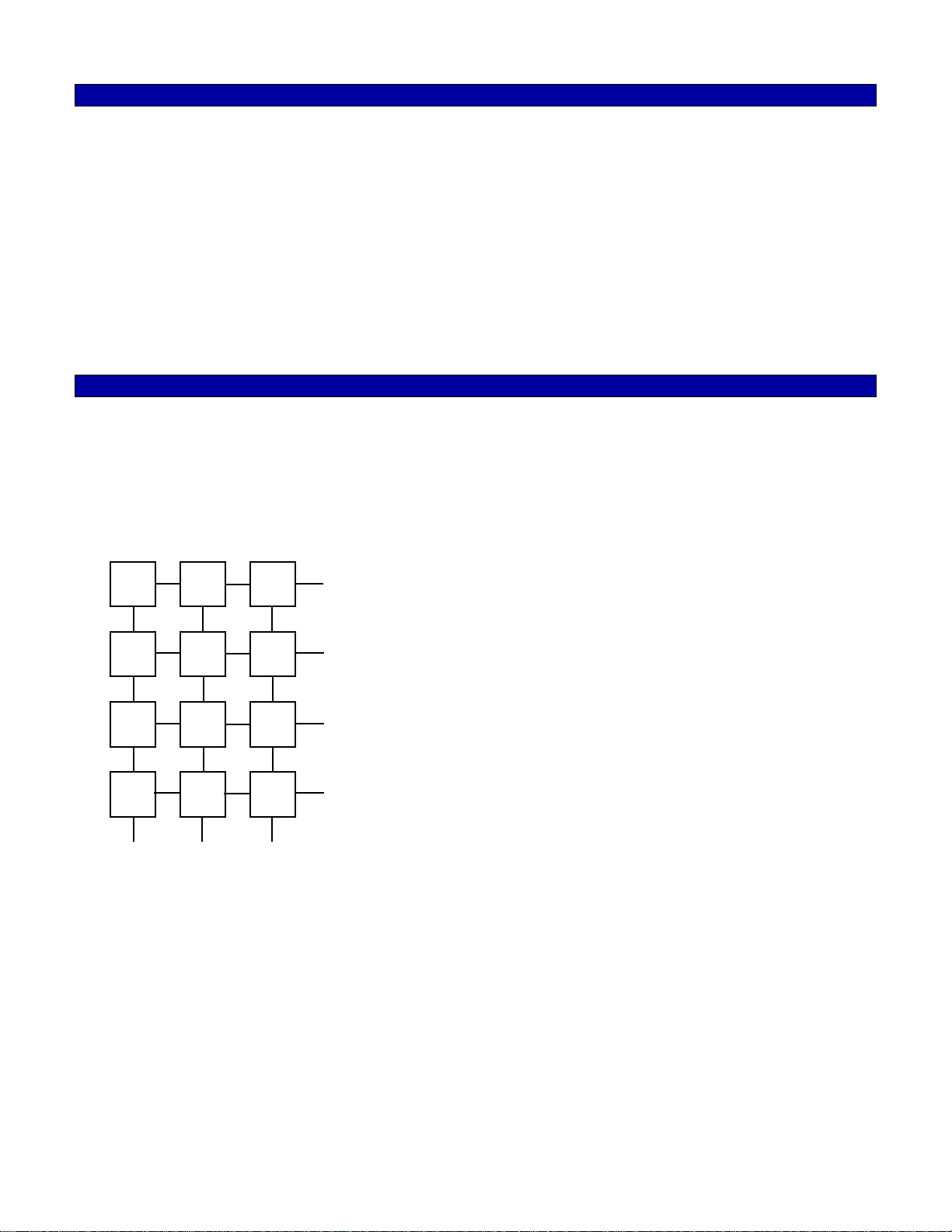
The keyboard provides a short between a column and a row on IC U1. This sets the internal Divide by N Counter,
so that the proper high & low tone groups are generated.
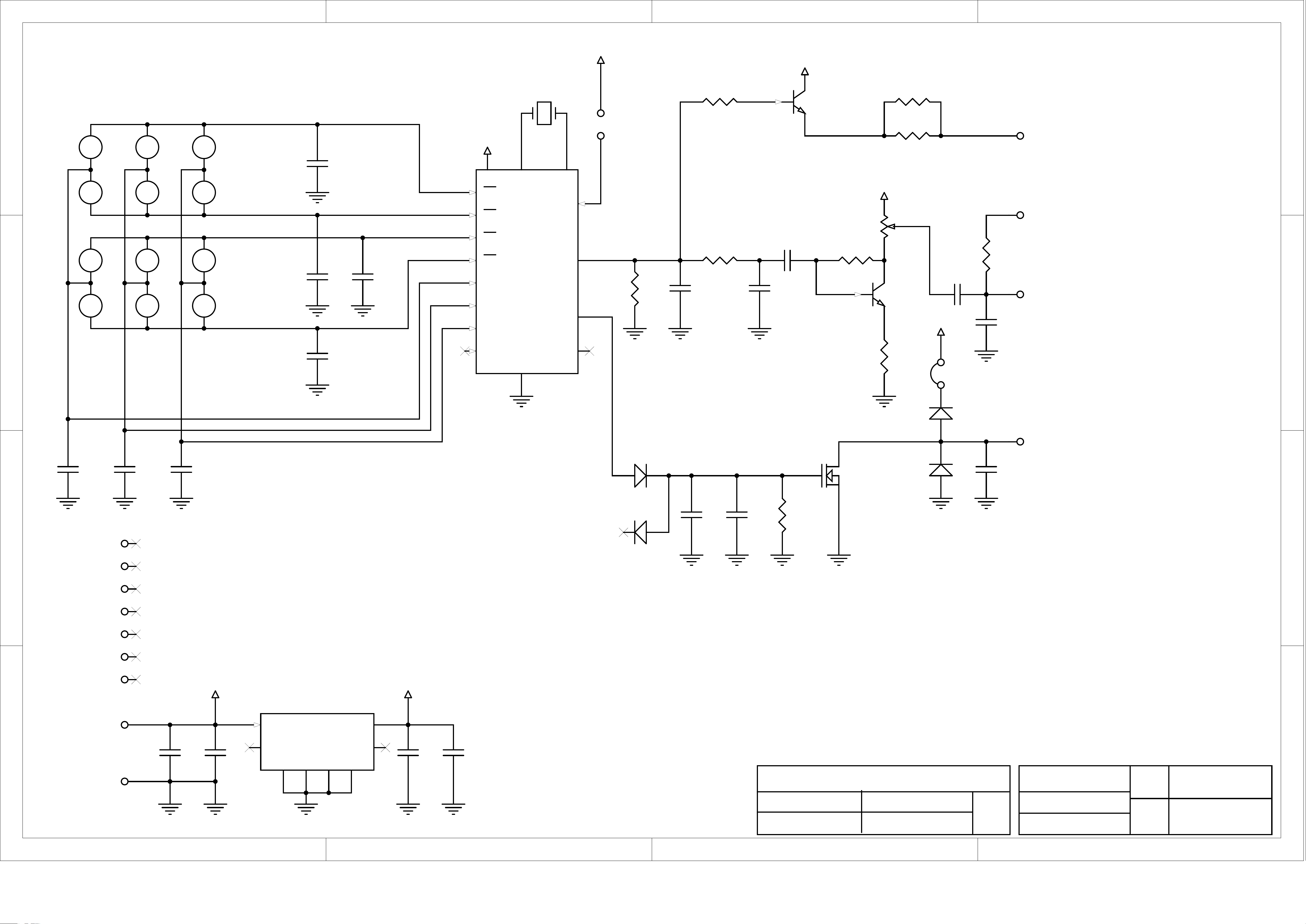
The synthesized high and low group tones are output on Pin 16 of U1 and are fed through low pass filter R5 C13
to amplifier Q2 and modulation level pot RP1. Audio is also fed from Pin 16 to the base of the side tone transistor
Q1. Q1 is an emitter follower, whose ground is completed through the radio speaker via the Blue lead. Resistors
R2 and R3 can be lowered to increase the level in the speaker. Use caution if the current gets too high, it can
burn up the resistor R2, R3 or Q1.
The high tones are pre-emphasized 3dB over the low tones. This is an internal feature of U1. Pre-emphasis
helps to compensate for high frequency roll off, which occurs on the phone lines and in some audio circuits. Any
high frequency components generated by the digital to analog conversion process in U1 are filtered out by the low
pass filter R5 and C13. The value of C13 can also be changed to roll off the twist that is built into U1.
Transmit audio is output on the Green lead and is normally connected to the high impedance port. The low
impedance output on the brown lead can be used in applications where direct connection to a low impedance
circuit is necessary.
Depressing any key causes pin 10 of U1 to go high, which in turn forward biases Q3. The automatic Push-To-
Talk circuit consists of D1, C15, C16, R10, and Q3. The time constant of C15, C16 and R10 produces a PTT
output for approximately 2 seconds.
The TTE-7 input voltage is regulated at +5 volts by VR1. VR1 will work from a low of 6.5 volts to 24 volts.
TECHNICAL NOTES
Radio Compatibility: Midian has taken the utmost care to ensure the option board integrates into the radio with
minimal impact to the features of the radio. However, some features may not be available in the radio when an
option board is used. If a feature is not available, please contact Midian to see if the feature can be added.
MIDIAN CONTACT INFORMATION
Midian Electronics Inc.
2302 East 22nd Street
Tucson, Arizona 85713 USA
Orders: 1-800-MIDIANS
Phone: 520-884-7981
Fax: 520-884-0422
E-mail: sales@midians.com
Web: www.midians.com

1
1
2
2
3
3
4
4
D D
C C
B B
A A
560p
C1 .1u
C2
100p
C4
100p
C5
100p
C6
100p
C7
100p
C8
100p
C9
100p
C10
100p
C11
100p
C12
.022u
C13
.1u
C14
560p
C17
220p
C18
.1u
C19
123
456
789
*0#
5087
R1
14
R2
13
R3
12
R4
11
C1
3
C2
4
C3
5
VSS
6
VSS
6
MUTE 10
TONE 16
STE 15
OSC2
8
OSC2
8
OSC1
7
OSC1
7
VDD
1
VDD
1
C4
9XMSW 2
U1
47K
R1 82R
R2
82R
R3
10K
R4
39K
R5
470K
R6
330R
R8
47K
R9
HI ZHI Z
P2A
+6.5V to 24V+6.5V to 24V
P2B
LO ZLO Z
P2C
GNDGND
P2D
SPKRSPKR
P2E
N/CN/C P2F
N/CN/C P2G
N/CN/C P2H
PTT OUTPTT OUT
P2I
N/CN/C P2J
N/CN/C P2K
N/CN/C P2M
N/CN/C P2M
KEYPAD
B25
Q2
D25
Q1
VIN
+5V
BSS
Q3
2.2M
R10
.47u
C15
.47u
C16
.47u
C3
10K
11
33
22
RP1
VIN
LEVEL ADJ
+5V
SINGLE
TONE
ENABLE
DTMF OUT
3.579545 MHz.
Y1
A7
2 1
D2A
A7
31
D2B
A7
2 1
D1A
A7
3 1
D1B
VIN
78L05
VIN
8VOUT 1
2
GNDGND
3
GNDGND
6
GNDGND
7
GNDGND
N/C
4N/C 5
VR1
VIN +5V
*
JP1
0R
JP2
Midian Electronics, Inc.
DATE:
DESIGN
2008/10/09
AIB
AWSDWN.BY
2008/10/09REV.
APPR SCHEMATIC
COPYRIGHT 2008
TTE-7 REV
SHEET
PROJECT NAME
DOCUMENT NUMBER
PRJ_7163_TTE7
7163-A-1
A-1
P0BP101P0BP102
P0BP201P0BP202
P0BP301P0BP302
P0BP401P0BP402
P0BP501P0BP502
P0BP601P0BP602
P0BP701P0BP702
P0BP801P0BP802
P0BP901P0BP902
P0BP1001P0BP1002
P0BP1101P0BP1102
P0BP1201P0BP1202
P0C101P0C102
P0C201P0C202
P0C301P0C302
P0C401P0C402
P0C501P0C502
P0C601P0C602
P0C701P0C702
P0C801P0C802
P0C901P0C902
P0C1001P0C1002 P0C1101P0C1102
P0C1201P0C1202
P0C1301P0C1302
P0C1401 P0C1402
P0C1501P0C1502
P0C1601P0C1602
P0C1701P0C1702 P0C1801P0C1802
P0C1901 P0C1902
P0D1A01
P0D1A02
P0D1B01
P0D1B03
P0D2A01
P0D2A02 P0D2B01
P0D2B03
P0JP101 P0JP102
P0JP201 P0JP202
P0P2A01
P0P2B02
P0P2C03
P0P2D04
P0P2E05
P0P2F06
P0P2G07
P0P2H08
P0P2I09
P0P2J010
P0P2K011
P0P2M013
P0P2M013
P0Q10B
P0Q10CP0Q10E
P0Q20B
P0Q20CP0Q20E
P0Q30D
P0Q30G
P0Q30S
P0R101 P0R102 P0R201 P0R202
P0R301 P0R302
P0R401P0R402
P0R501 P0R502 P0R601 P0R602
P0R801P0R802
P0R901P0R902
P0R1001P0R1002
P0RP101
P0RP102
P0RP103
P0U101
P0U102
P0U103
P0U104
P0U105
P0U106 P0U107
P0U108
P0U109
P0U1010
P0U1011
P0U1012
P0U1013
P0U1014
P0U1015
P0U1016
P0VR101
P0VR102
P0VR103
P0VR104 P0VR105
P0VR106
P0VR107
P0VR108
P0Y101 P0Y102
P0C301
P0C401
P0JP102
P0U101
P0VR101
P0C102
P0C202
P0C302
P0C402
P0C502
P0C602
P0C702
P0C802
P0C902
P0C1002 P0C1102
P0C1202
P0C1302
P0C1502
P0C1602
P0C1702 P0C1802
P0D2A02
P0P2D04
P0Q30S
P0R402
P0R802
P0R1002
P0U106
P0VR102
P0VR103
P0VR106
P0VR107
P0BP101
P0BP201
P0BP301
P0C1101
P0U1014
P0BP102P0BP401P0BP702P0BP1001
P0C501
P0U103
P0BP202P0BP501P0BP802P0BP1101
P0C601
P0U104
P0BP302P0BP601P0BP902P0BP1201
P0C701
P0U105
P0BP402
P0BP502
P0BP602
P0C1001
P0U1013
P0BP701
P0BP801
P0BP901
P0C901
P0U1012
P0BP1002
P0BP1102
P0BP1202
P0C801
P0U1011
P0C1201
P0R101
P0R401
P0R501
P0U1016
P0C1301
P0C1401P0R502 P0C1402
P0Q20B
P0R601
P0C1501
P0C1601
P0D1A01
P0Q30G
P0R1001
P0C1701
P0D2A01
P0P2I09
P0Q30D
P0C1801
P0C1902 P0P2C03
P0R902
P0C1901
P0RP102
P0D1A02
P0U1010
P0D1B03
P0D2B03
P0JP201
P0JP101
P0U1015
P0P2A01
P0R901
P0P2E05
P0R202
P0R302
P0P2F06
P0P2G07
P0P2H08
P0P2J010
P0P2K011
P0P2M013
P0Q10BP0R102
P0Q10E
P0R201
P0R301
P0Q20C
P0R602
P0RP103
P0Q20EP0R801
P0U102
P0U107
P0Y101
P0U108
P0Y102
P0U109
P0VR104 P0VR105
P0C101
P0C201
P0JP202
P0P2B02
P0Q10C
P0RP101
P0VR108

- This page intentionally left blank-

C1
P0C101
P0C102
C2
P0C201
P0C202
C3
P0C301
P0C302
C4
P0C401
P0C402
C5
P0C501
P0C502
C6
P0C601
P0C602
C7
P0C701
P0C702
C8
P0C801
P0C802
C9
P0C901
P0C902
C10
P0C1001
P0C1002
C11
P0C1101
P0C1102
C12
P0C1201
P0C1202
C13
P0C1301
P0C1302
C14
P0C1401
P0C1402
C15
P0C1501
P0C1502
C16
P0C1601
P0C1602
C17
P0C1701
P0C1702
C18
P0C1801
P0C1802
C19
P0C1901
P0C1902
D1
P0D101
P0D102
P0D103
D2
P0D201
P0D202
P0D203
JP1
P0JP101
P0JP102
JP2
P0JP201
P0JP202
P2
P0P201P0P202P0P203P0P204P0P205P0P206P0P207P0P208P0P209P0P2010P0P2011P0P2012P0P2013
Q1
P0Q10B
P0Q10C
P0Q10E
Q2
P0Q20B
P0Q20C
P0Q20E
Q3
P0Q30D
P0Q30G
P0Q30S
R1
P0R101
P0R102
R2
P0R201
P0R202
R3
P0R301
P0R302
R4
P0R401
P0R402
R5
P0R501
P0R502
R6
P0R601
P0R602
R8
P0R801
P0R802
R9
P0R901
P0R902
R10
P0R1001
P0R1002
RP1
P0RP101
P0RP102
P0RP103
U1
P0U101
P0U102
P0U103
P0U104
P0U105
P0U106
P0U107
P0U108P0U109
P0U1010
P0U1011
P0U1012
P0U1013
P0U1014
P0U1015
P0U1016
VR1
P0VR101
P0VR102
P0VR103
P0VR104P0VR105
P0VR106
P0VR107
P0VR108
Y1
P0Y101
P0Y102
P0Y10GND
P0C301
P0C401P0JP102
P0U101
P0VR101
P0C102P0C202 P0C302
P0C402
P0C502
P0C602
P0C702
P0C802
P0C902P0C1002
P0C1102
P0C1202
P0C1302
P0C1502
P0C1602
P0C1702
P0C1802
P0D202
P0P204
P0Q30S
P0R402
P0R802
P0R1002
P0U106
P0VR102
P0VR103P0VR106
P0VR107
P0Y10GND
P0BP101P0BP201P0BP301 P0C1101
P0U1014
P0BP102
P0BP401
P0BP702
P0BP1001
P0C501
P0U103
P0BP202
P0BP501
P0BP802
P0BP1101
P0C601
P0U104
P0BP302
P0BP601
P0BP902
P0BP1201
P0C701
P0U105
P0BP402P0BP502P0BP602
P0C1001
P0U1013
P0BP701P0BP801P0BP901
P0C901
P0U1012
P0BP1002P0BP1102P0BP1202
P0C801
P0U1011
P0C1201
P0R101
P0R401
P0R501
P0U1016
P0C1301
P0C1401P0R502
P0C1402P0Q20B
P0R601
P0C1501
P0C1601 P0D101
P0Q30GP0R1001
P0C1701
P0D201
P0P209
P0Q30D
P0C1801P0C1902
P0P203
P0R902
P0C1901
P0RP102
P0D102P0U1010
P0D203
P0JP201
P0JP101
P0U1015
P0P201
P0R901
P0P205
P0R202P0R302
P0Q10B
P0R102P0Q10E
P0R201P0R301
P0Q20C
P0R602
P0RP103
P0Q20E
P0R801
P0U107 P0Y101
P0U108 P0Y102
P0C101P0C201
P0JP202
P0P202
P0Q10C
P0RP101
P0VR108

BP1
P0BP101P0BP102 BP2
P0BP201P0BP202
BP3
P0BP301P0BP302
BP4
P0BP401P0BP402 BP5
P0BP501P0BP502 BP6
P0BP601P0BP602
BP7
P0BP701P0BP702 BP8
P0BP801P0BP802 BP9
P0BP901P0BP902
BP10
P0BP1001P0BP1002 BP11
P0BP1101P0BP1102
BP12
P0BP1201P0BP1202
P0C102P0C202 P0C302
P0C402
P0C502
P0C602
P0C702
P0C802
P0C902P0C1002
P0C1102
P0C1202
P0C1302
P0C1502P0C1602
P0C1702
P0C1802
P0D202
P0P204
P0Q30S
P0R402
P0R802
P0R1002
P0U106
P0VR102
P0VR103P0VR106
P0VR107
P0Y10GND
P0BP101 P0BP201 P0BP301
P0C1101
P0U1014
P0BP102
P0BP401
P0BP702
P0BP1001
P0C501
P0U103
P0BP202
P0BP501
P0BP802
P0BP1101
P0C601
P0U104
P0BP302
P0BP601
P0BP902
P0BP1201
P0C701
P0U105
P0BP402 P0BP502 P0BP602
P0C1001
P0U1013
P0BP701 P0BP801 P0BP901
P0C901
P0U1012
P0BP1002 P0BP1102 P0BP1202
P0C801
P0U1011
P0C101P0C201
P0JP202
P0P202
P0Q10C
P0RP101
P0VR108
Table of contents
Other Midian Electronics Recording Equipment manuals