Chapter 2. The Flow of Entire Installation
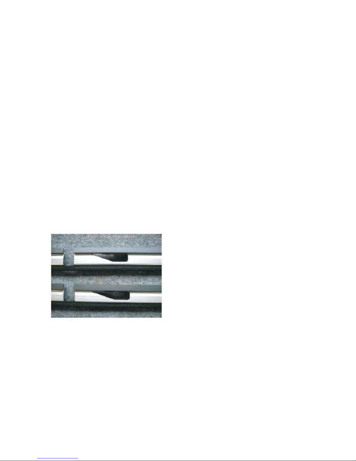
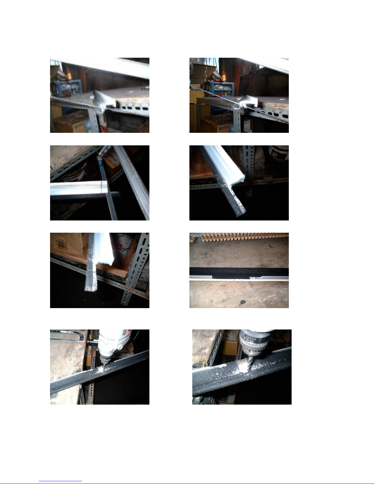
1. Mute Rail Installation
① Separate the action from the piano and adjust mute rail length suitably for the action bracket
not to interfere the mute rail (Cutting the centre bracket’s part out)
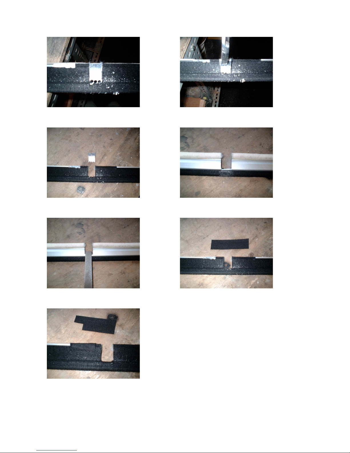
② STANDARD type mute bar can be cut and adjusted according to the various action styles
③ Separate the piano damper rail
④ Install mute rail to the action
⑤ Install mute rail parallel with the strings without bend ※ Important
⑥ Install spring and E ring at uni bracket
⑦ Install mute lever, adjust mute on and off position
※ Important point : parallel mute rail with the strings -> same distance from every hammer
shanks, ensure the damper’s moving space when mute off
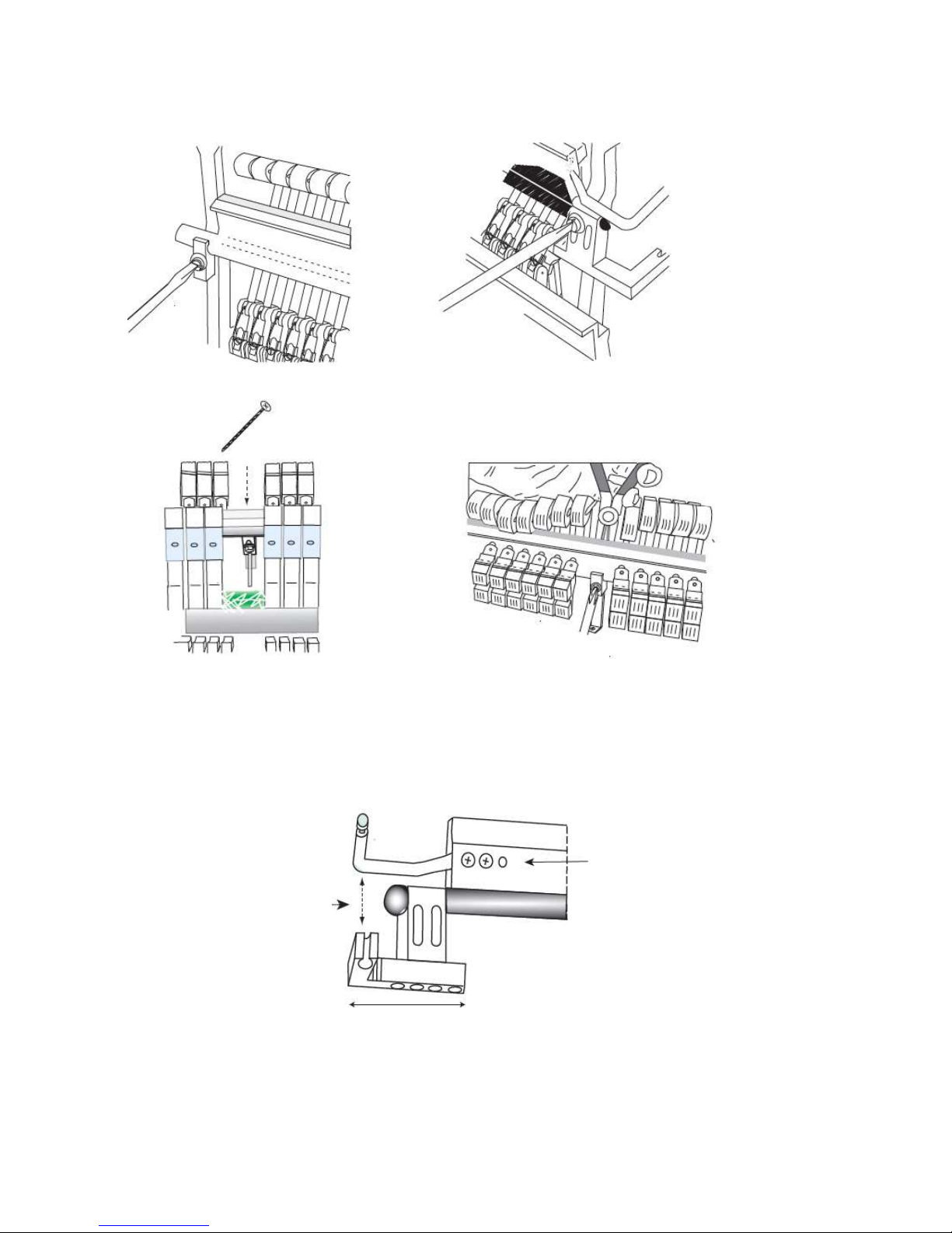
2. Sound Source Installation
① Separate the keys from the key bed, and put the sensor rail, and put several black keys
upon the key sensors for sensors, to adjust the springs height for correct sensor positioning.
② After setting the springs, install the sensor plate carefully.
③ Connect the main cable tightly to the connector in treble part of the sensor plate. Put the 5
black keys around the screws which shows the standard height of the sensor plate.
④ Adjust the height carefully by adjusting the distance between the bottom of black keys and
the top of the sensor rail
⑤ Install the Main Unit under the key bed inside, and connect the main cable.
⑥ Install the Control Unit under the key bed outside(front), and fix the headphones hanger.
⑦ Install pedal sensors.
⑧ Arrange the electric wires and sensor cables
※ Important point : Tidy arrangement of the main cables connected between key & pedal
sensors and main unit
3. Finishing
① Let-Off adjustment for muting position
② Calibration(Initializing) the system
③ Monitor the sounds, and adjust the sensitivity of each key if needed
④ After installation finished, check any noise happening.
※ Important point :
Let-Off : Adjust the hammer shanks take out before touching the mute rail
Check the dampers working properly during acoustic play (mute off).