MIDORI CP36U Series User manual

1
・TMR Element Contactless Angle Sensor
・Effective Electrical Travel : 18° ~ 360°
・Absolute Linearity : ±0.2%FS (FS=360°)
・2-wire 4-20mA Current Output
・Equipped with output adjustment functions
・IP50 / IP67
【Material】
● Housing : Aluminum
● Shaft : Stainless Steel
● Ball Bearing : Stainless Steel
TMR Contactless Angle Sensor
CP36U Series
■Dimensions (mm)
Programmable/ Detachable Type
3/2020

2
■Linearity / Output Resolution
FS >=45°
FS >=30°
See the chart below
1000m/s26ms 3axis 6directions 3times each (JIS C60068-2-27)
-40 ~ +85℃
-40 ~ +105℃
±1.0° (FS=360 ~ 91°) / ±0.5° (FS=90 ~ 18°)
IP50/ IP67 (Except cable tips)
100V/m: 10K ~ 1GHz (ISO11452-2, 3)
CISPR25 CLASS2
24±8VDC
■Specifications
Effective Electrical Travel
Output Range
Input Voltage
Absolute Linearity
See the chart below
Adjustable (@4mA±1mA, @20mA±1mA, Output Direction CW/CCW)
■Output Characteristics
ESD
Load Resistance
Temp. Drift (Category Temp. Range)
Shock
Category Temp. Range
Storage Temp. Range
Vibration
Output Resolution
Torque
Resolution
■Mounting (mm)
0.2%FS
■Schematic
18° ~ 360°
(IP50) 1mN・m MAX. / (IP67) 10mN・MAX.
600Ω MAX. (Vin=@DC24V)
1KHz±10%
Approx. 12Bit
Approx. 12Bit
Approx. 11Bit
Approx. 10Bit
Approx. 9Bit
FS >=180°
FS >=90°
FS >=18°
0.3%FS
0.5%FS
Linearity
Electrical Travel
FS=360°
IEC61000-4-2 Contact ±4KV, Air ±8KV, Classification Criteria B
Update Cycle
IP Level
EMS
EMI
0.9%FS
1.3%FS
2.1%FS
Approx. 12Bit
200m/s25~500Hz/20min 3axis 2H each (JIS C60068-2)
3/2020

3
・Mounting plate
Mounting Cleats: 2pcs
Programable type of CP36U Series provides the following user-adjustable functions by using the setting panel.
[Setting Panel]
1) Electrical Angle Range Setting
2) Zero/ Span Adjustment
3) Output Increase Direction Setting
4) Reset Setting
1) Electrical Angle Range Setting
■Options
The actuary assurance range: FS= 18° ~ 360°
FS adjustable angle range: 1° ~ 360°
Enable to reset any angle to Start (ST: 4mA) and END
(ED: 20mA) positions.
■Accessories
■User-adjustable Functions
3/2020

4
2) Zero/ Span Adjustment
Adjustment Resolution: 4.55μA (Theoretical value)
3) Output Increase Direction Setting
Reset output increase direction CW or CCW.
4) Reset Setting
1. Revert back to the last setting.
2. Return to factory setting
1. Connect the setting panel to the CP36U cable.
2. Supply DC24V input to CP36U.
3. Have your own device ready to monitor sensor output if it is necessary.
1. 『+/20 』Button
2. 『S 』Button
3. 『-/4 』Button
Press the buttons firmly.
■Setting Panel Operating Instructions
~ The First Step~
~Setting Panel Layout~
Reset the output value at zero position (4mA) and span
position (20mA) within the ±1mA range.
Zero Position: 4mA±1mA
Span Position: 20mA±1mA
1. Output CW Direction: Positive Linear Output
2. Output CCW Direction: Negative Linear Output
3/2020

5
1) Electrical Angle Range Setting
1. Press and hold both 『+/20 』and 『-/4 』buttons for 3 seconds or longer to start setting mode.
2. Rotate the shaft of CP36U until the angle to be set as the start (4mA) position.
Then press the 『-/4 』button. CP36U creates 4mA output at this point.
3. Next, rotate the shaft of CP36U until the angle to be set as the end (20mA) position.
Then press the 『+/20 』button. CP36U creates 20mA output at this point.
4. After setting Start and End positions, press 『S 』button for more than 3 seconds
to complete the setting.
Pressing and hold 『+/20 』,『S 』, and『-/4 』buttons at the same time for more than 3 seconds to cancel the setting.
If none of the buttons were pressed for more than 5 minutes during the setting process, the setting mode is canceled.
2) Zero/ Span Adjustment
2)-1 Fine adjustment of 4mA output
1. Press and hold 『-/4 』buttons for 3 seconds or longer to start setting mode.
2. Decrease the 4mA output value.
Press 『-/4 』button …4mA output value will decrease each time the button is pressed.
Press and hold the button and the value will decrease continuously.
3. Increase the 4mA output value.
Press 『+/20 』button … 4mA output value will increase each time the button is pressed.
Press and hold the button and the value will increase continuously.
4. Press 『S 』button for more than 3 seconds to complete the setting.
~ Setting Procedures~
3/2020

6
Pressing and hold 『+/20 』,『S 』, and『-/4 』buttons at the same time for more than 3 seconds to cancel the setting.
If none of the buttons were pressed for more than 5 minutes during the setting process, the setting mode is canceled.
2)-2 Fine adjustment of 20mA output
1. Press and hold 『+/20 』buttons for 3 seconds or longer to start setting mode.
2. Decrease the 20mA output value.
Press 『-/4 』button …4mA output value will decrease each time the button is pressed.
Press and hold the button and the value will decrease continuously.
3. Increase the 20mA output value.
Press 『+/20 』button … 4mA output value will increase each time the button is pressed.
Press and hold the button and the value will increase continuously.
4. Press 『S 』button for more than 3 seconds to complete the setting.
Pressing and hold 『+/20 』,『S 』, and『-/4 』buttons at the same time for more than 3 seconds to cancel the setting.
If none of the buttons were pressed for more than 5 minutes during the setting process, the setting mode is canceled.
3) Output Increase Direction Setting
3)-1 Increase output direction to CW shaft rotation
1. Press and hold both 『+/20 』and 『S 』buttons for 3 seconds or longer to start setting mode.
2. Press 『+/20 』button …Increase output direction to CW shaft rotation.
3. Press 『S 』button for more than 3 seconds to complete the setting.
Pressing and hold 『+/20 』,『S 』, and『-/4 』buttons at the same time for more than 3 seconds to cancel the setting.
If none of the buttons were pressed for more than 5 minutes during the setting process, the setting mode is canceled.
3/2020

7
3)-2 Increase output direction to CCW shaft rotation
1. Press and hold both 『-/4 』and 『S 』buttons for 3 seconds or longer to start setting mode.
2. Press 『-/4 』button …Increase output direction to CCW shaft rotation.
3. Press 『S 』button for more than 3 seconds to complete the setting.
Pressing and hold 『+/20 』,『S 』, and『-/4 』buttons at the same time for more than 3 seconds to cancel the setting.
If none of the buttons were pressed for more than 5 minutes during the setting process, the setting mode is canceled.
4) Reset Setting Function
4)-1 When reverting back to the last setting
1. Start Reset Mode
Stop power supply to CP36U and press and hold 『+/20 』,『S 』, and『-/4 』buttons altogether.
Continue to hold the buttons and supply the power to CP36U.
Wait for more than 3 seconds before releasing the buttons.
2. Press and hold 『-/4 』buttons for 3 seconds or longer to revert back to the last setting.
3. Press 『S 』button for more than 3 seconds to complete the setting.
Pressing and hold 『+/20 』,『S 』, and『-/4 』buttons at the same time for more than 3 seconds to cancel the setting.
If none of the buttons were pressed for more than 5 minutes during the setting process, the setting mode is canceled.
4)-2 Return to factory setting
1. Start Reset Mode
Stop power supply to CP36U and press and hold 『+/20 』,『S 』, and『-/4 』buttons altogether.
Continue to hold the buttons and supply the power to CP36U.
Wait for more than 3 seconds before releasing the buttons.
3/2020
8
2. Press and hold 『+/20 』buttons for 3 seconds or longer to revert back to the last setting.
3. Press 『S 』button for more than 3 seconds to complete the setting.
Pressing and hold 『+/20 』,『S 』, and『-/4 』buttons at the same time for more than 3 seconds to cancel the setting.
If none of the buttons were pressed for more than 5 minutes during the setting process, the setting mode is canceled.
1) Linearity and output resolution of the total electrical angle.
2) Output Display
3)
4) Product warranty after output adjustment
Although we fully recognize the performance and accuracy of CP36U may be influenced by adjusting the output using the control panel,
please use this product once you have thoroughly read and understood the proper procedure.
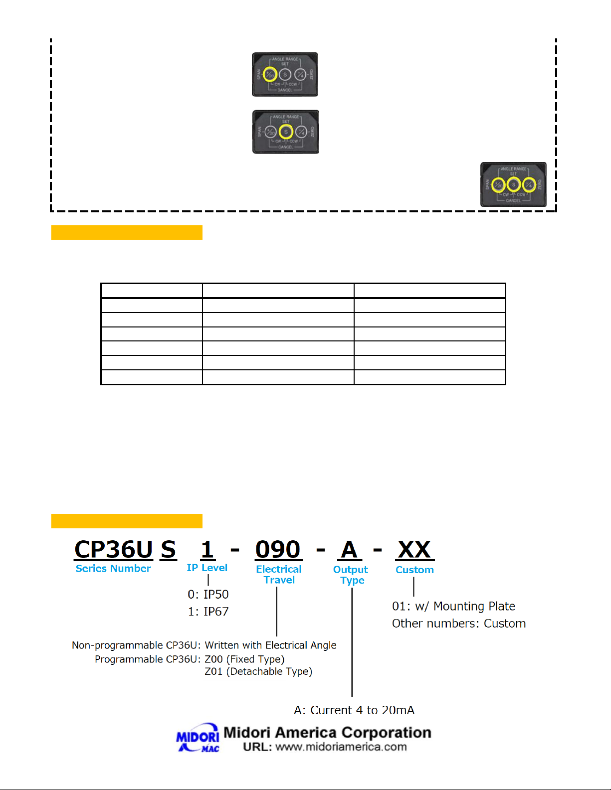
■Model Number Designation
FS >=18°
2.1%FS
Approx. 9Bit
CP36U and the setting panel are not equipped with output display device. Please have your own decide ready to monitor sensor output.
Neither CP36U nor the setting panel has the function to notice that the setting is complete. Please read this manual and understand the
necessary steps before initiating the setting procedure.
FS >=45°
0.9%FS
Approx. 11Bit
FS >=30°
1.3%FS
Approx. 10Bit
FS >=180°
0.3%FS
Approx. 12Bit
FS >=90°
0.5%FS
Approx. 12Bit
After adjusting the electrical angle range, the accuracy and the output resolution of CP36U at each set electrical angle are shown in the
following chart.
Electrical Travel
Linearity
Resolution
FS=360°
0.2%FS
Approx. 12Bit
■Note
3/2020
Table of contents
Popular Accessories manuals by other brands


Voksi
Voksi Explorer user manual

BOMANN
BOMANN KSG 232 user manual

KooPower
KooPower DQ-608 user manual

Revolution Lightning
Revolution Lightning RNET-OCC-HV-P-WS-J Specifications and installation

Lightolier
Lightolier Calculite RM-INC specification

Endress+Hauser
Endress+Hauser Turbimax CUS51D technical information

SCHUNK
SCHUNK FTE-AXIA Assembly and operating manual

komodo
komodo KDBEDDBAIRA quick start guide

Dorner
Dorner AquaGard 7350 Series Installation, Maintenance, and Parts Manual

Mamiya
Mamiya Universal Specifications

Nostalgia Electrics
Nostalgia Electrics Coca-Cola BC24COKE instruction manual

Exact solutions
Exact solutions V1000E manual