Midtronics EXP-717 User manual
Expandable Electrical
Diagnostic Platform
For testing 12-volt automotive batteries
INSTRUCTION MANUAL
EXP-717


•3•
Contents
Chapter 1: Before You Begin.......................................................................................7
Safety..............................................................................................................................7
General Precautions ............................................................................................................. 7
Conventions Used in This Manual...................................................................................7
Note: Truck info...............................................................................................................8
Registering Your Analyzer...............................................................................................8
Chapter 2: Description................................................................................................. 9
Test Leads, Connectors, and Data Ports ........................................................................9
Display and Keypad ......................................................................................................10
Data Entry Methods.......................................................................................................11
Menu icons...........................................................................................................................11
Option Buttons .....................................................................................................................11
Scrolling Lists.......................................................................................................................11
Alphanumeric Entry..............................................................................................................11
Menu Maps....................................................................................................................12
Main Menu .......................................................................................................................... 12
Print/View Menu.................................................................................................................. 13
Info Menu ............................................................................................................................ 13
Utilities Menu....................................................................................................................... 14
Chapter 3: Test Preparation.......................................................................................15
Inspecting the Battery....................................................................................................15
Testing Out-of-Vehicle...................................................................................................15
Testing In-Vehicle..........................................................................................................15
Connecting the Battery Test Cable................................................................................15
Setting User Preferences..............................................................................................16
Contents

•4•
Chapter 4: Battery Test .............................................................................................. 17
Additional Test Requirements........................................................................................18
Vehicle Type / Taxi test........................................................................................................ 18
Surface Charge................................................................................................................... 18
Select the Temperature (not always)...................................................................................18
Before / After Charge ..........................................................................................................19
Deep Scan Test................................................................................................................... 19
Battery Test Results ......................................................................................................20
Chapter 5: QC Test ..................................................................................................... 21
Chapter 6: Utilities......................................................................................................22
Config Tester.................................................................................................................22
Display...........................................................................................................................23
Shop..............................................................................................................................24
Coupon..........................................................................................................................25
Edit Coupon...................................................................................................................25
Language ......................................................................................................................25
Format Disk...................................................................................................................25
Update...........................................................................................................................25
Battery Menu (only for the Quality Control Test) ...........................................................26
Contents

•5•
Chapter 7: Info Menu..................................................................................................27
Totals.............................................................................................................................27
Transfer.........................................................................................................................27
Version info....................................................................................................................27
Chapter 8: Print/View .................................................................................................28
View Test.......................................................................................................................28
View QC Test.................................................................................................................28
Chapter 9: Truck info.................................................................................................. 29
Chapter 10: Troubleshooting..................................................................................... 30
The Display Does Not Turn On .....................................................................................30
The STATUS LED Flashes (Midtronics Printer) ............................................................30
Data Will Not Print.........................................................................................................30
Chapter 11: Tester Internal Batteries........................................................................32
Battery Power Indicator.................................................................................................32
Replacing the Tester Batteries ......................................................................................32
Contents

•6•
Contents

•7•
Chapter 1: Before You Begin
!Safety
Because of the possibility of personal injury, always use extreme caution when working with
batteries. Follow all manufacturers’ instructions and BCI (Battery Council International) safety
recommendations.
General Precautions
• DANGER—RISK OF EXPLOSIVE GASES: Batteries can produce a highly explosive mix
of hydrogen gas and oxygen, even when the battery is not in operation. Always work in a
well-ventilated area. Never smoke or allow a spark or flame in the vicinity of a battery.
• WARNING—REQUIRED BY CALIFORNIA PROP. 65: Battery posts, terminals, and
related accessories contain lead and lead compounds, chemicals known to the state of
California to cause cancer and birth defects or other reproductive harm. Wash hands
after handling.
• Batteryacid ishighlycorrosive. Ifacidentersyoureyes, immediatelyflushthem thoroughly
with running cold water for at least 15 minutes and seek medical attention. If battery acid
gets on your skin or clothing, wash immediately with water and baking soda.
• Always wear proper safety glasses or face shield when working with or around
batteries.
• Keep hair, hands, and clothing as well as the analyzer cords and cables away from
moving engine parts.
• Remove any jewelry or watches before you start servicing the battery.
• Use caution when working with metallic tools to prevent sparks or short circuits.
• Never lean over a battery when testing, charging or jump starting it.
Conventions Used in This Manual
To help you learn how to use your analyzer, the manual uses these symbols and typographical
conventions:
The safety symbol followed by the word WARNING or CAUTION indicates
instructions for avoiding hazardous conditions and personal injury.
The word CAUTION without the safety symbol indicates instructions for
avoiding equipment damage.
The wrench symbol indicates procedural notes and helpful information.
The text for keypad buttons and soft-key functions are in bold capital letters.
The text for screen options are in regular capital letters.
!
CAUTION
UP ARROW
POST TYPE
Chapter 1: Before You Start

•8•
Note: Truck info
In the following chapters we will describe the menu structure and functionality of the passenger car
software. In many of the cases this will also serve the Truck tester version. More info can be found
in chapter 9.
Registering Your Analyzer
Before using your tester, we recommend that you register it online
to activate your warranty. Registration will also make it faster and
easier for you to obtain technical support and service, and order
parts and accessories. In addition, you’ll be alerted to any important
information, like product updates and special offers.
To register, log on at www.midtronics.com/warranty.html and have
your serial number ready. The number is at the bottom of the label
on the back of the analyzer (Figure 1).
Figure 1:
Serial Number Location
Chapter 1: Before You Start
•9•
Chapter 2: Description
Chapter 2: Description
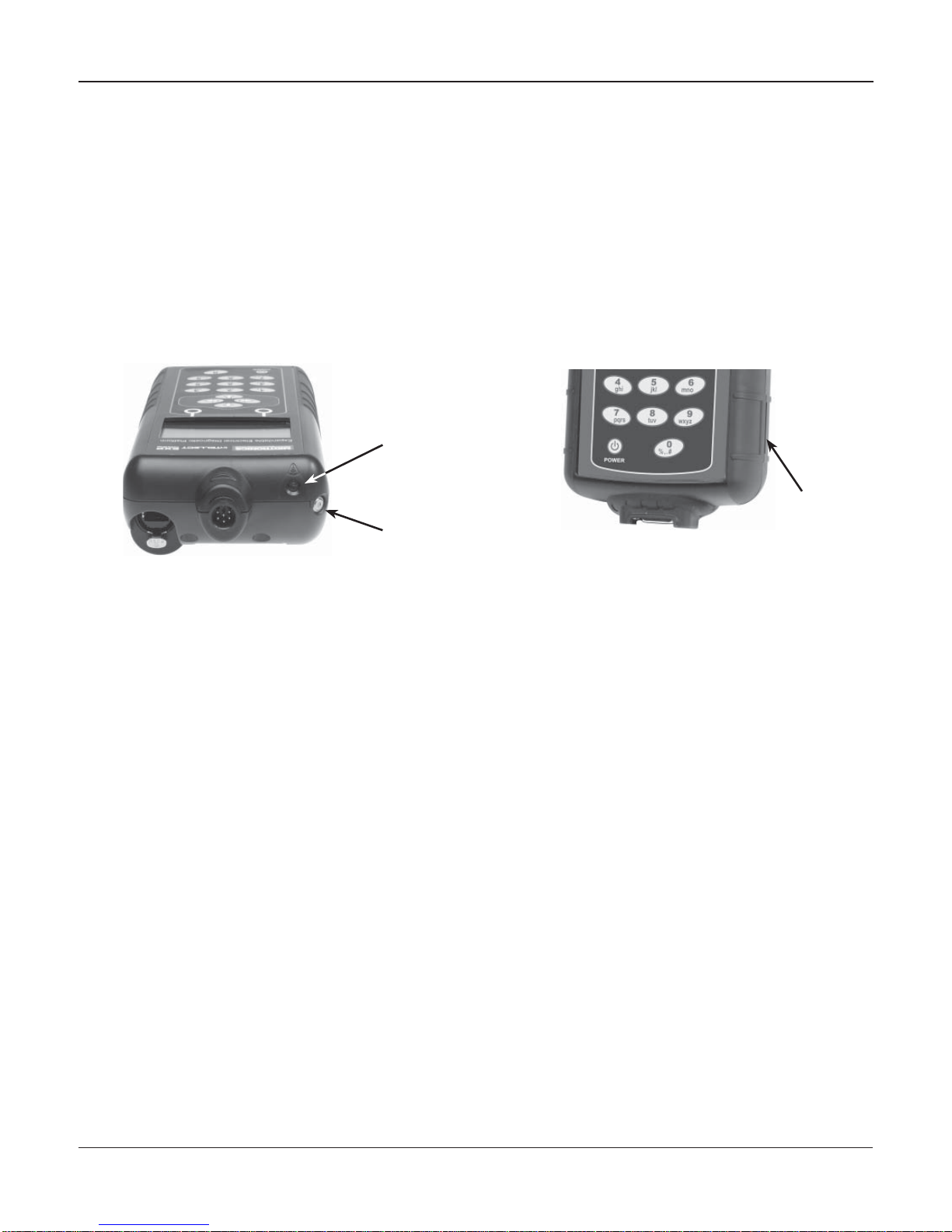
Test Leads, Connectors, and Data Ports
For the cable test leads, there are two connectors on the top of the tester (Figure 3).
• For the battery test cable, there is a 6-pin connector with a locking ring.
6-pin
connector
IR data
transmitter
IR temperature
sensor DB-9
connector
for future
expandability
Accessories
port
SD card slot
for future
upgrades
There are two IR data ports on the top of the Tester (Figure 3).
• An IR data transmitter, which transmits test results to the optional IR printer.
• An IR temperature measurement sensor.
The tester also has a DB-9 connector for future expandability and an SD card slot for future soft-
ware upgrades or data logging. (Figure 4).
Figure 3: Top of EXP Figure 4: Bottom of EXP

•10 •
The Internal Batteries
Status Indicator, which ap-
pears in the screen’s top
left corner, lets you know
the status and charge
level of the analyzer’s 6 1.5 V
batteries. The X shown in the
figure shows that the tester is
powered by the battery you’re
testing to conserve the internal
batteries.
Press the two Soft Keys linked
to the bottom of the screen to
perform the functions displayed
above them. The functions
change depending on the menu
or test process. So it may be
helpful to think of the words
appearing above them as part
of the keys. Some of the more
common soft-key functions are
SELECT, BACK, and END.
When you connect the tester
to a battery it functions as a
voltmeter. The
voltage read-
ing appears above the left soft
key until you move to other
menus or functions.
In some cases, you can use
the Alphanumeric Keypad to
enter numerical test parameters
instead of scrolling to them with
the ARROW keys.
You’ll also use the Alphanu-
meric Keys to create and edit
customer coupons. The keypad
includes characters for punctua-
tion. To add a space, press the
RIGHT and LEFT ARROW keys
simultaneously.
The Selection Area below the
Title Bar contains items you se-
lect or into which you enter infor-
mation. The area also displays
instructions and warnings.
The Directional Arrows on the
display show you which Arrow
Keys to press to move to other
icons or screens. The Up
and Down Directional
Arrows,forexample,let
you know to press the
UP and DOWN ARROW
keys to display the screens that
are above and below the current
screen.
The Left and Right Directional
Arrows let you know to use the
LEFT or RIGHT ARROW keys
to highlight an icon for selection.
Another navigational aid is the
Scroll Bar along the right side
of the screen. The position of its
scroll box tells you which menu
screen you’re viewing.
The Title Bar shows you the
name of the current menu, test
tool, utility, or function.
Press the POWER button to turn
the Tester on and off. The Tes-
ter also turns on automatically
when you connect its test leads
to a battery.
Whichever way you turn on the
Tester, it always highlights the
icon and setting you last used
for your convenience.
Top
or only
screen
Middle
screen Last
screen
Scroll Bar
Scroll
Box
Chapter 2: Description
Display and Keypad
The keypad and display work together to help you quickly find and use the right tools at the right time.
The display also keeps you on track with on-screen navigation aids, directions and messages. Figure
6shows how the elements on the screen relate to the keypad.
Figure 6: Main Menu and Keypad

•11 •
Data Entry Methods
To perform a particular test or function, the tester will ask for different types of information. This means
that the methods you use to enter information will change depending on the type of information re-
quested. The four types of entry methods are described below.
Typically, the soft key below the right half of the screen confirms your choice, although the word above
it may vary.
Menu icons
A menu icon is a graphical representation of a function you can select, such as the Diode Icon in the
DMM Menu. To select an icon, use the LEFT or RIGHT ARROW key to highlight it. To confirm your
selection, press the appropriate soft key.
Option Buttons
Some lists have option buttons before each item. To select an item, use the UP/DOWN ARROW keys
to move the dot into the button next to the item you want. You can also use the alphanumeric keypad
to enter the number preceding the option button. To confirm your selection, press the appropriate soft
key.
Scrolling Lists
Scrolling lists contain items that extend above and below the screen or the selection box that contains
them. To indicate that there are more items, the symbols appear to the right of the first visible or
highlighted item on the list.
To select from this type of list, use the UP/DOWN ARROW keys to scroll to the item, or use the keypad
to enter your choice, and press the appropriate soft key.
Alphanumeric Entry
Some selections require you to use the alphanumeric keypad. These “user-defined” selections have
a cursor to the right of the last character.
Use the UP/DOWN ARROW keys to highlight a line for editing. Display the character, symbol, or
number you want by rapidly pressing its key as many times as needed. If you pause, the cursor moves
to the right. To backspace, press the LEFT ARROW key. Use the RIGHT ARROW key to add a space.
Use the UP/DOWN ARROW keys to highlight a line for editing. When finished, press the appropriate
soft key to save your settings.
Chapter 2: Description

•12 •
Menu Maps
This section will help you get to your destination while letting you know what test leads you may need
when you arrive. The test leads are represented by symbols for their connectors.
Main Menu
The Main Menu is the starting point for all tools and utilities, which are depicted as icons. Some icons
lead directly to the function they represent, while others are menu icons that lead to two or more
functions. Menu icons are marked here with an asterisk (
*
) and are mapped on the following pages.
MAIN MENU (Screen 1)
MAIN MENU (Screen 2)
Tests a battery using
the battery information
you select in a series of
screens.
Includes a test counter,
data transfer utility, the
EXP software version
and serial number.
Enables you to view your
stored test results and
print them to an optional
IR printer.
Nine utilities, many of
which customize your
user interface.
*
*
*
(voltmeter reading) an icon
(voltmeter reading) an icon
Chapter 2: Description
Quality Control Mode for
testing Stock batteries or
compound batteries.
•13 •
An optional IR software
and hardware package
enables you to transfer
test data to a PC.
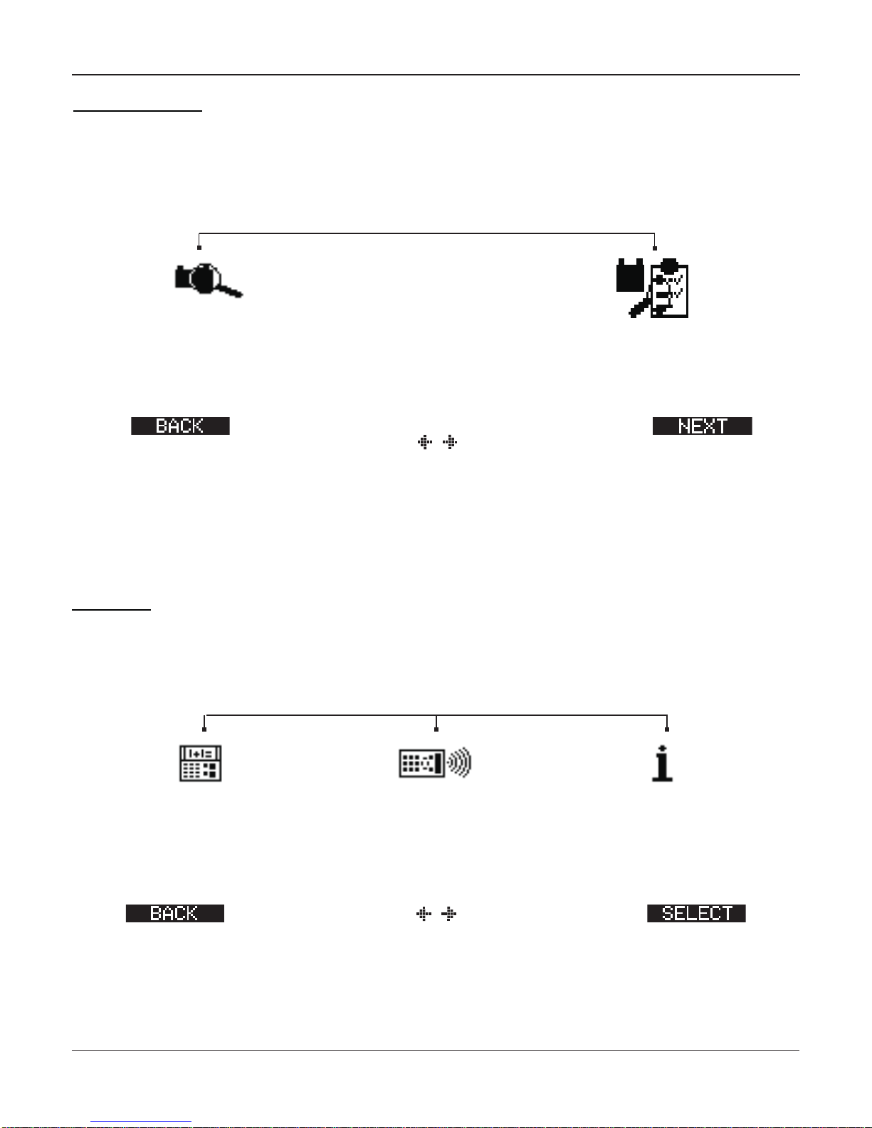
Info Menu
The Info Menu has three utilities to help you manage your test data, and track the usage and history
of your tester.
Displays the total Battery
and System Tests per-
formed since the tester
was first used.
Displays the software
version, total tests from
first use, and the serial
number.
REPORTS
to Main Menu an icon
Chapter 2: Description
Displays the last Battery
and System Test results.
Sends the results to an
optional IR printer.
REPORTS
to Main Menu an icon
Print/View Menu
The tester stores the last test results in its memory until you perform another test. To review or print
results before you retest, select a test type in the Print/View Menu.
Displays the last QC Test
result. Sends the result
to an optional IR printer.

•14 •
SETUP (Screen 1)
SETUP (Screen 2)
SETUP (Screen 3)
Settings to adjust the
date and time etc.
Enables you to add a
custom header to printed
test results.
Settings to adjust the
screen contrast and
backlight time.
If you’ve created a cou-
pon in the Edit Coupon
utility, use Coupon to
turn it on and off.
Enables you to create a
coupon at the bottom of
printed test results.
Sets the language of the
display and printouts.
an icon
Utilities Menu
The Utilities Menu lets you customize your analyzer to suit your needs.
to Main Menu an icon
to Main Menu an icon
to Main Menu
Formas the SD card to
receivedata.Alsoerases
all data on the card.
Updates the software us-
ing files on an SD card.
Chapter 2: Description
Enables you to configure
the printer to IrDA.
SETUP (Screen 4)
Change, add or delete batteries
for Compound/Stock mode
an icon
to Main Menu

•15 •
Chapter 3: Test Preparation
Inspecting the Battery
Before starting the test visually inspect the battery for:
• Cracked, buckled, or leaking case. If you see any of these defects, replace the battery.
• Corroded, loose, or damaged cables and connections. Repair or replace them as
needed.
• Corrosion on the battery terminals, and dirt or acid on the case top. Clean the case and
terminals using a wire brush and a mixture of water and baking soda.
• Low electrolyte level. If the electrolyte level is too low, add distilled water to fill up to 1/2
above the top of the plates and fully charge the battery. Do not overfill.
• Corroded or loose battery tray and hold-down fixture. Tighten or replace as needed.
Testing Out-of-Vehicle
The preferred battery test location is in the vehicle. However, if you plan to test out of the vehicle:
• Always disconnect the negative cable from the battery first and reconnect it last.
• Always use a carry tool or strap to lift and transport the battery.
Testing In-Vehicle
The preferred test position is at the battery posts. If you must test at a remote-post location, it should
have both a positive and negative post.
At the start of the test, make sure all vehicle accessory loads are off, the key is not in the ignition, and
the doors are closed.
Connecting the Battery Test Cable
CAUTION: Do not connect the tester to a voltage source greater than 30 Vdc.
Connect the battery test cable to the tester by first aligning the cable connector’s 6 pins with the
holes on top of the tester. Firmly insert the connector and tighten the locking ring.
Connect the clamps to the battery: the red clamp to the positive (+) terminal and the black clamp to
the negative (–) terminal.
Chapter 3: Test Preparation

•16 •
If you connect the clamps in the wrong polarity (positive to negative or negative to positive), the tester
displays CLAMPS REVERSED! Reconnect the clamps correctly.
To make sure both sides of the clamps are gripping the terminals, rock the each clamp back and forth.
Apoor connection will prevent testing, and the tester will display the message CHECK CONNECTION.
If the message reappears after you have correctly reconnected the clamps, clean the terminals and
reconnect.
The message WIGGLE CLAMPS can indicate that there is no good connection between the clamps
and the battery posts. This could be because of corrosion on the posts. Wiggle the clamps and
retest.
If there is a problem with the cable resistance the same message can appear. Contact Midtronics for
further action.
Note: When the battery voltage is below 0.5 Volt the message CHECK CONNECTION can appear.
Fully charge the battery and retest.
Setting User Preferences
Before starting your test you may want to customize the use of your analyzer by setting preferences
in the Utility Menu. The menu has settings for the display’s date and time, the contrast and backlight
time, a utility to customize printouts for the optional IR printer, among others.
To conserve the analyzer’s internal batteries, the tester will turn off after 30 seconds of
inactivity.
Chapter 3: Test Preparation

•17 •
Chapter 4: Battery Test
The tester will guide you through the steps of selecting your battery test parameters and interpreting
the results. Before you start the test, review the instructions in Chapter 3: Test Preparation.
1. Select the battery LOCATION.
1 OUT OF VEHICLE
2 IN VEHICLE
Press the NEXT soft key to continue. The BACK soft key returns you to the Main Menu at the
start of the test and to the previous screen as you progress.
2. Select the Ah value
Read the value from the battery and confirm with ENTER. Press the UP/DOWN ARROW or
enter the value with the keypad.
3. Select the BATTERY TYPE.
1 REGULAR
2 VRLA
3
SPIRAL
4 GEL
Press the
NEXT soft key to continue.
4. Select the BATTERY STANDARD
1 CCA
2 JIS
3
DIN
4 SAE
5
IEC
6
EN
Press the
NEXT soft key to continue.
Chapter 4: Battery Test

•18 •
5. Enter the CCA value of the battery
Press the
UP/DOWN ARROW keys or use the numeric keys to select the
battery rating or in the case of JIS, the part number. To increase your
scrolling speed, hold down the UP or DOWN ARROW key.
Press the NEXT soft key to start the test.
For the next few seconds the tester will display the word TESTING and a stopwatch
while it evaluates the battery.
6. Vehicle ID
For further vehicle identification you can add a 17 digit text. This text will also appear on
the print-out.
Additional Test Requirements
For a more decisive result the tester may ask for additional information or probe deeper into the
battery’s condition.The following messages and instructions may appear before the analyzer displays
the results of your test.
Vehicle Type / Taxi test
The Taxi test is used to perform an extra test.
1. Follow the instructions on the screen.
Surface Charge
The battery will hold a surface charge if the engine has been running or after the battery has been
charged. The tester may prompt you to remove the surface charge before it begins testing.
1. Follow the instructions indicating when to turn the headlights on and off.
2. The tester will resume testing after it detects that the surface charge is removed.
Select the Temperature (not always)
Point the tester at the battery, make sure the tester is within a 5 cm reach of the battery to capture the
correct temperature.
Chapter 4: Battery Test

•19 •
Before / After Charge
In some cases the tester may ask you wheather the battery was charged prior to the test. When the
vehicle has been driven just prior to the test answer the question with BEFORE CHARGE. Press
NEXT to continue.
Deep Scan Test
In some cases the tester may need to further analyze the battery to determine whether the battery
should be replaced or it has a significant chance to be recovered. It will then conduct a Deep Scan Test
of the battery for a few seconds.
TESTING
DEEP SCAN TECHNOLOGY
PLEASE WAIT . . . . . . . . . .
After the Deep Scan Test the tester will display the results.
The next section describes the battery test decisions and suggests actions to take.
Chapter 4: Battery Test

•20 •
Battery Test Results
After the test the tester will display one of five battery decisions with the complete results in a series
of screens as shown in Figure 14. Use the UP/DOWN ARROW keys to scroll through each result. To
send the results to an IR printer, press the PRINT soft key. To return to the Main Menu, press the END
soft key.
Figure 14
Table 1: Battery Decisions and Recommendations
Decision Recommended Action
GOOD BATTERY Return the battery to service.
CHARGE & RETEST Fully charge the battery. Allow the battery to rest before retesting.
Failure to fully charge the battery before retesting may cause false
readings. If CHARGE & RETEST appears again after you fully charge
the battery, replace the battery.
REPLACE BATTERY Replace the battery and retest. A REPLACE BATTERY result may also
mean a poor connection between the battery cables and the battery.
After disconnecting the battery cables, retest the battery using the out-
of-vehicle test before replacing it.
BAD CELL–REPLACE Replace the battery.
Chapter 4: Battery Test
Battery decision Measured voltage
Rating units you
selected for the test
All test results are stored on the SD Card. This data can be copied from the card and used
to verify / compare results.
Table of contents
Other Midtronics Medical Equipment manuals

Popular Medical Equipment manuals by other brands


Optopol
Optopol SOCT Copernicus + Service manual

Mediana
Mediana RESCATE PERU Heart On AED A10 quick start guide

St. Jude Medical
St. Jude Medical Tendril MRI LPA1200M user manual

Stryker
Stryker 1080 Operation manual

ORTHOSERVICE RO+TEN
ORTHOSERVICE RO+TEN iper35 manual

OAKWORKS
OAKWORKS Spine Positioning System II user manual