Miele GDU 45/65 User manual

GDU 45/65, GDU 60/65
PMontageanweisung Dekorset
QFitting instructions Decor Set
öInstallation instructions for the GDU Decor Set
XMonteringsveiledning dekorsett
WMonteringsanvisning Dekor-sæt
ZGDU-muuntosarjan asennusohje
M.-Nr. 04 582 051

PMontageanweisung Dekorset . . . . . . . . . . . . . . . . . . . . . . . . . . . . . . . . . . . . 3
QFitting instructions Decor Set . . . . . . . . . . . . . . . . . . . . . . . . . . . . . . . . . . . 11
öInstallation instructions for the GDU Decor Set. . . . . . . . . . . . . . . . . . . . . . 18
XMonteringsveiledning dekorsett . . . . . . . . . . . . . . . . . . . . . . . . . . . . . . . . . 26
WMonteringsanvisning Dekor-sæt . . . . . . . . . . . . . . . . . . . . . . . . . . . . . . . . . 33
ZGDU-muuntosarjan asennusohje . . . . . . . . . . . . . . . . . . . . . . . . . . . . . . . . 40
2

P
Diese Montageanweisung beschreibt
alle Arbeitsschritte, die sich auf das An-
bringen des Dekorsets GDU beziehen.
In der Gebrauchsanweisung des Ge-
schirrspülers finden Sie alle weiteren In-
stallations- und Montagehinweise.
Dekorset GDU für Unterbau (U)-Ge-
schirrspüler
Mit dem Dekorset (GDU) kann ein i-Ge-
schirrspüler zu einem U-Geschirrspüler
umgerüstet werden.
Basisgerät für einen Unterbau (U)-Ge-
schirrspüler ist ein integrierbarer (i)-Ge-
schirrspüler.
Das Dekorset GDU besteht aus:
1. Frontblende mit eingesetzter
Dekorplatte,
2. Sockelblende mit Haltewinkeln.
Das Dekorset GDU ist serienmäßig ge-
fertigt für Küchen mit einer Sockelhöhe
(Unterkante Küchenschranktür bis zum
Fußboden) von:
1. 70 mm (= 840 mm Einbauhöhe)
2. 120 mm (= 890 mm Einbauhöhe).
Für die Schweiz gelten folgende Sockel-
höhen:
1. 70 mm (= 840 mm Einbauhöhe)
2. 100 mm (= 870 mm Einbauhöhe)
Zur farblichen und maßlichen Anpas-
sung an die Front Ihrer Küche kann die
werkseitig eingesetzte Dekorplatte ge-
gen eine zur Küche passende Platte aus-
getauscht werden (siehe ,,Sonderfälle“).
Führen Sie zunächst die Arbeits-
schritte 1 - 3 durch!
Diese Arbeitsschritte finden Sie in
der Gebrauchsanweisung im Kapi-
tel ,,i-Geschirrspüler aufstellen“.
1. Arbeitsplattenschutz anbringen
2. Geschirrspüler in eine Nische
einbauen
3. Bedienungsblende anbringen
Bevor Sie die Bedienungsblende anbrin-
gen, müssen die Adapterleisten entfernt
werden (siehe Abbildung).
Dem Geschirrspüler liegen ein H-förmi-
ges Blech und zwei Schablonen bei.
Bewahren Sie diese Teile und die Adap-
terleisten auf, um den Geschirrspüler
z. B. beim Kauf einer neuen Küche wie-
der in ein i-Gerät umrüsten zu können.
Adapterleisten als ganzes Paket aus
den Steckschlitzen der Bedienungs-
blende drücken.
P
3

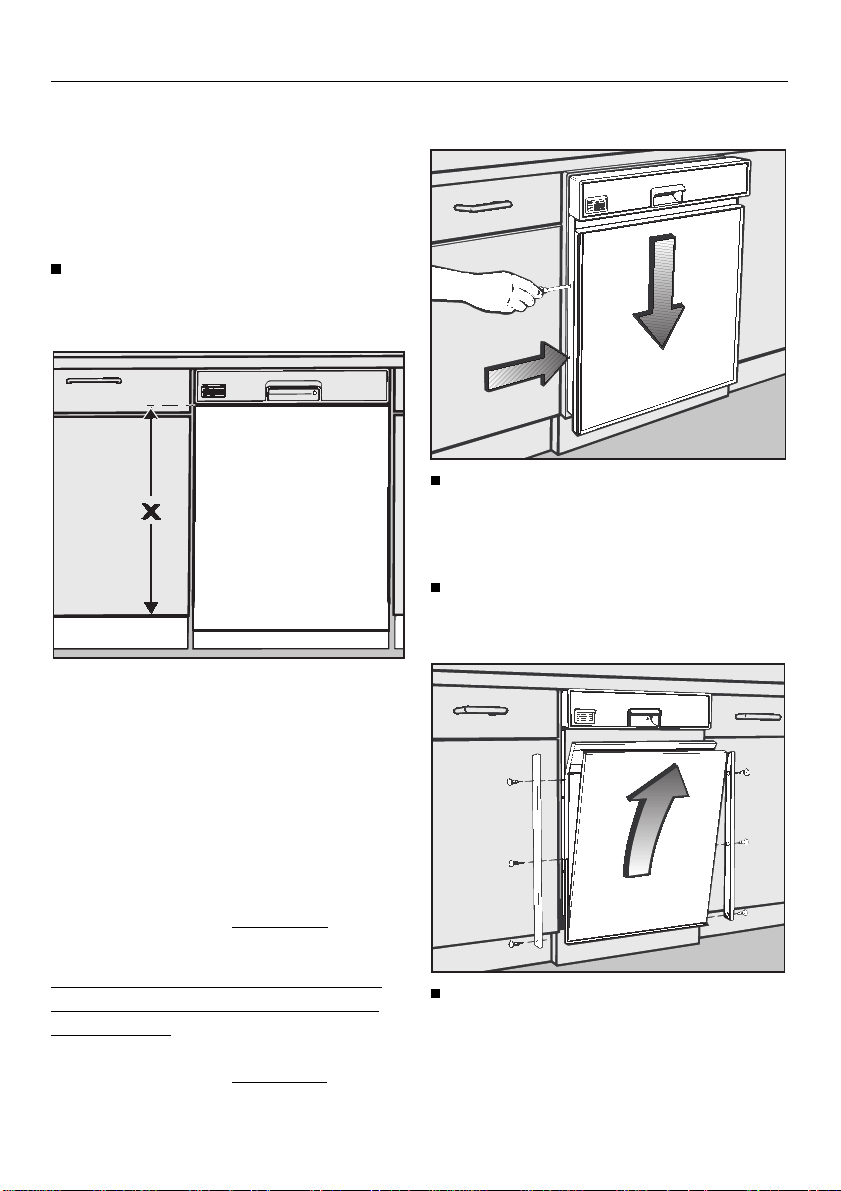
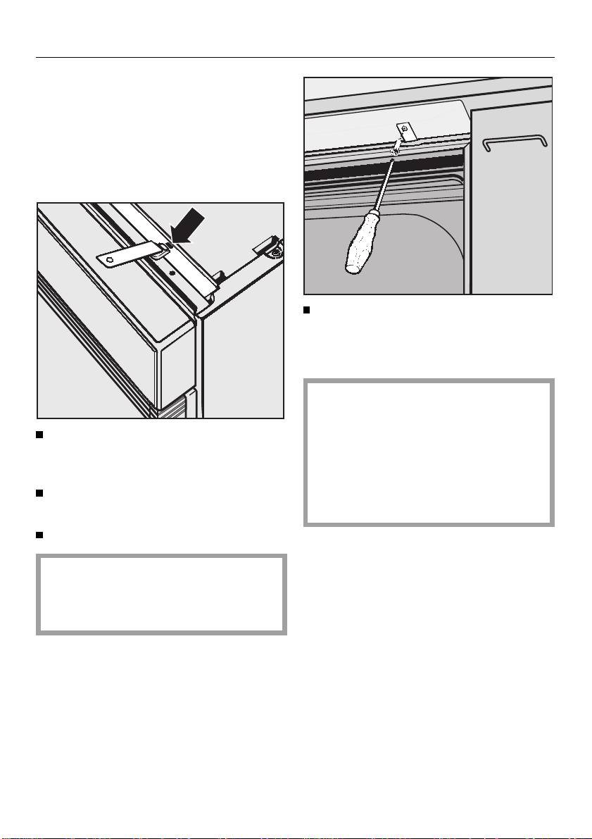
4.Frontblende anbringen
Geschirrspüler so weit aus der
Nische ziehen, daß die seitlichen
Befestigungsschrauben dfür die
Frontblende problemlos zugänglich
sind.
Frontblende schräg unter der Bedie-
nungsblende ansetzen bund in die
Schlitze des Türaußenblechs ein-
schwenken c.
Darauf achten, daß die Oberkanten
der Frontblende sauber von unten in
die Bedienungsblende eintauchen.
Befestigungsschrauben dan bei-
den Seiten des Türaußenblechs fest-
ziehen.
Mit beiliegenden Kunststoffstopfen
die Öffnungen der Befestigungsme-
chanik verschließen.
Geschirrspüler wieder in die Nische
schieben.
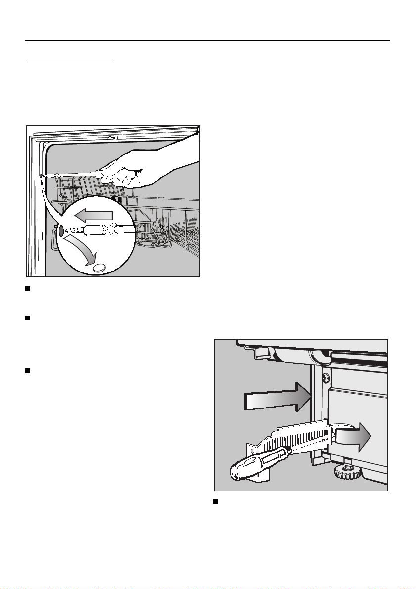
In den meisten Fällen paßt die Front-
blende farblich und maßlich zur Küche.
Dann mit Arbeitsschritt 7 fortfahren.
Sollte jedoch eine farbliche oder maßli-
che Anpassung erforderlich sein, siehe
Abschnitt ,,Sonderfälle“.
Sonderfälle
Die Frontblende kann wie folgt an die
Front der Küche angepaßt werden:
Fall A / Farbanpassung:
Die Frontblende paßt in der Höhe zu
den nebenstehenden Küchenschrän-
ken. Die serienmäßige Dekorplatte soll
jedoch durch eine farblich zur Küche
passende Platte ausgetauscht werden.
Für den Zuschnitt einer neuen Dekor-
platte werksseitige Maße entspre-
chend der Breite des Geschirrspü-
lers verwenden.
Dann mit Arbeitsschritt 6 fortfahren.
Fall B / Maßanpassung:
Die Frontblende soll in der Höhe den
nebenstehenden Küchenschränken an-
gepaßt werden.
Mit Arbeitsschritt 5 fortfahren.
Fall C / Farb- und Maßanpassung:
Die Frontblende soll in der Höhe und in
der Farbe den nebenstehenden Kü-
chenschränken angepaßt werden.
Mit Arbeitsschritt 5 fortfahren, um
das erforderliche Maß für den Zu-
schnitt der neuen Dekorplatte zu er-
mitteln.
Entsprechende Dekorplatte beschaf-
fen und danach mit Arbeitsschritt 6
fortfahren.
Werkseitige Zuschnittmaße der De-
korplatte:
H 653 x B 587 mm (bei 60 cm breiten
Geschirrspülern)
H 653 x B 437 mm (bei 45 cm breiten
Geschirrspülern)
P
4

5.Höhe der Dekorplatte
ermitteln
Bevor Sie das Maß Xausmessen, muß
die Höhe des Geschirrspülers der Ni-
schenhöhe angepaßt werden.
Die Füße des Geschirrspülers so
weit herausdrehen, daß er unter die
Arbeitsplatte stößt.
Maß X:
Unterkante der Bedienungsblende bis
Unterkante der Küchenschranktür.
Höhe der Dekorplatte: Maß X+ 2 mm.
Die Zugabe von 2 mm ist erforderlich,
damit die Frontplatte in die Bedienungs-
blende eintaucht (sicherer Halt).
Beispiel:
Maß X=625mm
+ 2 mm
Höhe Dekorplatte = 627 mm
In diesem Beispiel gilt für das Kürzen
der ensprechenden Teile (Fall B oder
C) folgendes:
werkseitige Höhe 653 mm
ermittelte Höhe – 627 mm
zu kürzendes Maß = 26 mm.
6.Frontblende anpassen
Geschirrspüler so weit aus der
Nische ziehen, daß die seitlichen
Befestigungsschrauben für die Front-
blende problemlos zugänglich sind.
Befestigungsschrauben an beiden
Seiten des Türaußenblechs lösen
und Frontblende absenken.
Dekorleisten abschrauben.
P
5

Fall A / Farbanpassung:
Dekorplatte austauschen.
Fall B / Maßanpassung:
Dekorleisten, Dekorplatte, Ausgleichs-
pappe und Styropor-Distanzstück
entnehmen und jeweils oben um das
zuvor ermittelte Maß kürzen
(im vorherigen Beispiel 26 mm).
Bitte beachten:
Dekorplatte und -leisten abkleben, um
beim Kürzen Kratzer zu vermeiden.
Dem Material entsprechendes Werk-
zeug benutzen! Eventuell einen Fach-
mann um Rat fragen.
Fall C / Farb- und Maßanpassung:
Wie Fall B, jedoch Dekorplatte nicht
kürzen, sondern gegen eine pas-
send zugeschnittene Platte austau-
schen.
Für den Zuschnitt verwenden Sie die
ermittelte Höhe (X+2 mm) und für
die Breite das werksseitige Zuschnitt-
maß entsprechend der Breite Ihres
Geschirrspülers (siehe Seite 4).
Wenn die neu eingesetzte Dekorplatte
stärker als 2 mm (max. 4 mm) ist, muß
die Ausgleichspappe aus der Front-
blende entfernt werden.
In allen oben genannten Fällen:
Frontblende wieder zusammenset-
zen und wie unter Punkt 4 beschrie-
ben an die Geschirrspülerfront an-
bringen.
Geschirrspüler in die Nische schie-
ben und ausrichten.
Danach mit Arbeitsschritt 7 fortfahren.
7.Türfederung einstellen
Die Türfedern sind richtig eingestellt,
wenn die halb geöffnete Tür (ca. 45 °
Öffnungswinkel) beim Loslassen in
dieser Stellung stehen bleibt.
Wenn die Tür in die waagerechte Stel-
lung absinkt, müssen die Türfedern ge-
spannt werden.
Wenn sie dagegen wieder hochfedert,
müssen die Federn entspannt werden.
Die Einstellschraube befindet sich in
der oberen Leiste vorne auf der linken
Seite des Geschirrspülers.
Tür des Geschirrspülers öffnen.
Die Türfederung mit einem Schrau-
bendreher (TORX T20) ausbalancie-
ren:
– Rechtsdrehung = spannen
– Linksdrehung = entspannen.
P
6

8.Geschirrspüler ausrichten
und festschrauben.
Um die Standfestigkeit zu gewährlei-
sten, muß der Geschirrspüler – nach-
dem er ausgerichtet ist – mit der Ar-
beitsplatte verschraubt werden.
Befestigungsbleche jeweils rechts
und links in die Schlitze stecken (sie-
he Pfeil).
Geschirrspüler in die Nische schie-
ben.
Tür des Geschirrspülers öffnen.
Das Loch im Befestigungsblech
und das Langloch im Arbeitsplatten-
schutz (Niroblech) müssen überein-
anderliegen.
Geschirrspüler rechts und links mit
den beiliegenden Senkkopfschrau-
ben (3,9 x 22) von unten an der Ar-
beitsplatte festschrauben.
Darauf achten, daß die Dichtung an
der Oberkante des Geschirrspülers
an der Arbeitsplatte anliegt.
Falls das nicht der Fall ist, den Ge-
schirrspüler weiter herausdrehen
(siehe Arbeitsschritt 2 in der Ge-
brauchsanweisung des Geschirr-
spülers).
Zum Vorgehen bei ,,Corian“- oder ,,Gra-
nit“-Arbeitsplatten die Gebrauchsanwei-
sung (Kapitel ,,i-Geschirrspüler aufstel-
len“) beachten.
P
7

Nur für die Schweiz:
Wenn die Arbeitsplatte keine Befesti-
gung nach Oben zuläßt (z. B. Granit-
arbeitsplatte), kann der Geschirrspüler
seitlich verschraubt werden.
Abdeckkappe von der Öffnung ent-
fernen.
Geschirrspüler an beiden Seiten
durch die Öffnungen festschrauben.
Dazu die beiliegenden Schrauben
mit aufgesteckter Buchse verwenden.
Abdeckkappe wieder auf die Öff-
nung setzen.
9.Sockelblende anbringen
Wenn der Geschirrspüler in einer Kü-
chenzeile mit einer durchgehenden Kü-
chen-Sockelblende eingebaut wird, ent-
fällt dieser Arbeitsschritt.
Die Anpassung der Sockelblende er-
folgt dann wie beim i-Geschirrspüler
(siehe Gebrauchsanweisung).
Die Höhe der mitgelieferten Sockelblen-
de ist ausgelegt für:
– einen maximalen Sockelrücksprung
(100 mm)
– eine maximale Einbauhöhe des Ge-
schirrspülers, welche durch das Her-
ausdrehen der Maschinenfüße
(max. 5 cm) erreicht wird.
Bei niedrigeren Einstellungen können
sich Tür und Sockelblende berühren,
wenn die Geschirrspülertür geöffnet
wird. Dann muß die Sockelblende in
der Höhe entsprechend gekürzt wer-
den.
Auf beiden Seiten Arretierungsfeder
zur Seite drücken und Haltewinkel
zunächst ganz einschieben.
P
8

Die Sockelblende hat zwei Schnittfugen.
Sockelblende mit den Schnittfugen
nach oben anschrauben und durch
gleichmäßiges Herausziehen dem
Sockelrücksprung der Küche anpas-
sen.
Bitte beachten:
Die Sockelblende läßt sich nicht zurück-
schieben. Sie muß abgeschraubt wer-
den, damit die Arretierungsfedern zur
Seite gedrückt und die Haltewinkel ein-
geschoben werden können.
Öffnen Sie die Tür des Geschirrspü-
lers vorsichtig so weit, bis die hintere
Unterkante der Geschirrspülertür an
die Sockelblende stößt.
Legen Sie einen Bleistift waagerecht
an die vordere Unterkante der Ge-
schirrspülertür an, und ziehen Sie da-
mit eine waagerechte Linie auf der
Sockelblende entlang.
Schrauben Sie die Sockelblende ab
Kürzen Sie die Sockelblende:
– entweder an dieser Linie mit einer
Säge;
oder besser
– an einer der vorhandenen Schnitt-
fugen, falls diese dicht an der ange-
zeichneten Linie liegt.
Die Sockelblende dann seitlich an
der Fuge anschneiden und brechen.
Schrauben Sie die Sockelblende mit
der Schnittkante nach unten wieder
an den Haltewinkeln an.
Falls die Tür des Geschirrspülers
sich jetzt nicht ohne weiteres öffnen
läßt, müssen Sie die Sockelblende
noch etwas kürzen.
P
9

Nur für die Schweiz:
Zwischen Haltewinkel und Sockelblende
kann ein Distanzstück eingesetzt werden.
Es paßt die Sockelblende für Sockelrück-
sprünge der Küche zwischen 30 mm
und 40 mm an.
P
10

Q
These instructions describe all the
steps necessary for fitting the GDU
decor set.
Please consult the separate dish-
washer Operating Instructions for all fur-
ther instructions on installation and fit-
ting.
Decor set GDU for a built-under (U)
dishwasher
With the GDU Decor set an integrated
(i) dishwasher can be converted to a
built-under (U) dishwasher.
The (i) model dishwasher is used as a
basis for this conversion to a (U) model.
The Decor set GDU consists of:
1. Front panel with
Decor panel (inset),
2. Plinth facia with fixing brackets
The Decor set GDU is produced as
standard for kitchens with a plinth
height (lower edge of kitchen unit door
to floor) of:
1. 70 mm (= 840 mm building-in height)
2. 120 mm (= 890 mm building-in height).
To match the dishwasher decor to the
colour and dimensions of your kitchen
furniture another decor panel can be
fitted in place of the one originally pro-
vided. See “Special situations”).
Carry out steps 1 - 3 .
The instructions for these steps are
given in the section on “Installation”
for integrated (i) dishwashers in the
Operating Instructions.
1. Attach the worktop protection
2. Install dishwasher into its niche.
3. Prepare and attach the control
panel.
Before fitting the control panel the adapt-
er strips (spacer bars) must be removed,
(see illustration).
An H-shaped bracket and two templates
are supplied with the dishwasher. Keep
these parts and the adapter strips in a
safe place, to use if you ever need to
convert the machine back to an inte-
grated one, for example in a new kitchen.
To remove the complete adapter
strip unit press out from the insertion
slots in the control panel. Then at-
tach the control panel.
Q
11

4.To fit the front panel
Pull the dishwasher out of its recess
enough to allow easy access to the
front panel fixing screws dat the
side.
Push the front panel at an angle
under the control panel band flap
down into the slits of the door front
outer panel c.
Make sure that the top edge of the
front panel slides up and sits neatly
in place under the control panel.
Tighten the screws don each side
of the door front outer panel.
Use the stoppers provided to blank
off the openings in the fixing mechan-
ism.
Push the dishwasher back into its
niche.
Usually the front panel will match the kit-
chen furniture in dimensions and col-
our. In this case proceed with Step 7.
However if the colour or measurements
do not match, see the Section “Special
situations”.
Special situations
The front panel can be matched to the
kitchen furniture fronts as follows:
Case A / Matching colour:
The front panel matches the neighbour-
ing kitchen units for height, but the
decor panel needs to be replaced by
one of a different colour.
To cut a new decor panel to size use
the dimensions set ex works, accord-
ing to the width of the dishwasher.
Then continue with Step 6.
Case B / Matching dimensions:
The front panel dimensions need to be
matched to those of the neighbouring
kitchen units.
Continue with step 5.
Case C / Matching colour and dimen-
sions:
The front panel needs to be matched in
height and colour to the neighbouring
kitchen units.
Continue with Step 5, to find out the
necessary dimensions for cutting the
new decor panel.
Obtain the appropriate decor panel
and then continue with Step 6.
Dimensions set ex-works for decor
panels:
H 653 x W 587 mm (for 60 cm wide
dishwashers)
H 653 x W 437 mm (for 45 cm wide
dishwashers)
Q
12

5.Define height of decor panel
Before taking measurement Xthe
height of the dishwasher must be ad-
justed to that of the recess.
Screw out the dishwasher feet until it
touches the underside of the work-
top.
Measurement X:
Measure the height, X, from the lower
edge of the control panel to the bottom
of the kitchen cabinet door.
Height of decor panel: Dimension X+
2 mm. The additional 2 mm are necess-
ary to enable the front panel to slide
into the control panel for a secure hold.
Example:
Dimension X= 625 mm
+2 mm
Decor panel height = 627 mm
Example, for Case B or Case C amount
to be cut off:
height ex works: 653 mm
required height – 627 mm
amount to be cut off: = 26 mm.
6.Aligning the front panel
Pull the dishwasher out of its recess
enough to allow easy access to the
fixing screws at the side.
Loosen the screws on each side of
the door front outer panel, and lower
the front panel.
Unscrew the decor strips.
Q
13

Case A / matching colour:
Exchange the decor panel.
Case B / matching dimensions:
Remove decor strips, decor panel,
filler card and polystyrene spacer
pieces, and shorten the panel from
the top by the amount calculated
(26 mm in the example given above).
Please note:
Use masking tape to protect the decor
panel and strips from scratches when
cutting the panel.
Use a cutting tool suitable for the ma-
terial. If necessary take advice from a
suitably competent person.
Case C / Matching colour and dimen-
sions:
As Case B, but do not shorten the
decor panel, replace it with a panel
already cut to size.
When cutting to size, use the height
dimension calculated (X+2 mm) and
the ex-works width dimension given
on page 12, according to your dish-
washer model.
If the new decor panel is thicker than
2 mm (max. 4 mm), remove the filler
card from the front panel.
In all the above-mentioned cases:
Reassemble the front panel and fit to
the machine as described under
Point 4.
Push the dishwasher back into the
niche and align.
Then continue with Step 7.
7.Adjusting the door springs
The door springs are correctly adjusted
when a half opened door (approx. 45°
opening angle) remains in that position
when released.
If the door drops down then the door
springs need to be tightened.
If however it rises up, then the springs
need to be released more.
The adjusting screw is located in the
upper front strip at the left hand side of
the dishwasher.
Open the dishwasher door.
Adjust the door springs using a Torx
screwdriver until it is balanced:
– turn clockwise = tighten
– turn anti-clockwise = loosen.
Q
14

8.Level and secure the
dishwasher
To ensure the stability of the dishwasher,
it must be screwed to the continuous
worktop after it has been positioned.
Fit the securing pieces into the slots
on both the left and right hand sides,
(see arrow).
Push the dishwasher into the recess.
Open the dishwasher door.
The hole in the securing piece must
line up with the oval hole in the niro
steel plate.
Screw the countersunk screws
(3.9 x 22) upwards through the se-
curing pieces on the left and right
hand sides into the work surface to
secure the dishwasher.
Ensure that the seal on the top
edge of the dishwasher fits directly
against the worktop. If this is not the
case, adjust the height-adjustable
scre feet more, (see Step 2 in the In-
stallation section of the Operating In-
structions).
With ’Corian’ or granite-type worktops
consult the Section on installing inte-
grated ’i’ dishwashers in the Operating
Instructions booklet.
Q
15

9.Fitting a plinth facia
This step is not carried out for dish-
washers installed in a kitchen with a
continuous kitchen plinth facia.
In that case align the plinth facia as de-
scribed for the integrated ’i’ dish-
washers in the Operating Instructions
booklet.
The height of the plinth facia supplied
is set for:
– A maximum plinth rebate of 100 mm.
– A maximum building-in height of the
machine, with the feet fully (5 cm) ex-
tended.
If these measurements are less than
the maximum, the door may hit the
plinth facia. If it does, trim the height of
the plinth facia accordingly.
On each side push the spring clips
aside and push the brackets right in.
The plinth facia has two cutting lines.
Q
16

Screw the plinth facia on with the cut-
ting lines towards the top, and pull
out evenly to adjust to the kitchen
plinth rebate.
Please note:
The plinth facia cannot be pushed
back. It must be unscrewed, so that
both spring clips can be pushed to the
sides and the brackets pushed in.
Carefully open the dishwasher door
until the rear bottom edge of the dish-
washer door hits against the plinth
facia.
Place a pencil horizontally at the
front lower edge of the dishwasher
door and draw a horizontal line
across the plinth facia.
Unscrew the plinth facia.
To shorten the plinth facia:
– Trim with the saw along this line,
or better
– cut along one of the cutting lines
provided if this is close enough.
Score the cutting line along the
plinth facia and then break off.
Screw the plinth facia back on to the
brackets, with the cutting line at the
bottom.
If the door does not open smoothly the
plinth facia may need further trimming.
Q
17

ö
These instructions describe the steps
necessary for installing the GDU decor
set.
Please consult the dishwasher Oper-
ations Manual for further information on
installing and operating the dishwasher.
GDU Decor set for a built-under (U)
dishwasher
With the GDU Decor set, an integrated
(i) dishwasher can be converted to a
built-under (U) dishwasher.
The GDU Decor set consists of:
1. A front panel with a Decor insret,
and
2. A toekick with mounting brackets
The GDU Decor set is made to fit kitchen
cabinets with a toekick height (lower
edge of cabinet door to floor) of
2 3/4 to 4 3/4 inches (70 - 120 mm).
The included decor insert can be
replaced with any 1/16” (1.5 - 2 mm)
thick material (plastic laminate,
melamine, veneer, etc.) to match your
cabinetry, if you so desire. (See
“Custom panels” on page 19).
Install the dishwasher as instructed in
its Operations Manual, making sure to
remove the adapter strip (spacer bars -
see illustration). Store the adapter
strips, the H-shaped bracket and the
two templates that came with the dish-
washer in a safe place.These will be
used if you decide to convert the dish-
washer back to an (i) model in the fu-
ture.
To remove the adapter strip from the
control panel, place the panel on a
table, printed side up, and gently
push down on the adapter strip near
the bottom of the control panel. This
will release the mounting bolts from
their slots.
Before proceeding, make sure the
following steps have been performed.
1. The steam deflector has been in-
stalled (if necessary).
2. The dishwasher has been placed
in position under the counter and
correctly levelled.
3. The adapter strip has been
removed.
ö
18

If you are installing the front panel from
the GDU Decor set as is, proceed as
follows. If you will be using a custom
front panel of different dimensions or
color, proceed to “Custom panels” in
the next column.
Step 4. Installing the front panel
Pull the dishwasher out from under
the countertop as far as necessary
to reach the locking screws located
on the side of the door, d.
Angle the top of the front panel under
the control panel, b, and align the
tabs with the slots on the door as you
position the panel in place, c. Make
sure that the top edges of the decor in-
sert and frame are completely seated
under the control panel.
Tighten the 4 screws, d, 2 on each
side of the door.
Use the provided caps to plug the
locking screw access holes.
Push the dishwasher back under the
countertop, and proceed to Step 7,
“Adjusting the door springs”.
Custom panels
A front panel can be made to match
the kitchen cabinets, depending on the
situation, as follows:
Situation A - Panel color needs
changing:
The front panel matches the neighbor-
ing cabinets in height, but the decor in-
sert needs to be replaced by one of a
different color.
Proceed to Step 6, “Removing the
front panel”.
Situation B - Panel needs to be short-
ened:
The front panel is too long and needs
to be shortened to match the neighbor-
ing cabinets.
Proceed to Step 5, “Calculating the
height of the decor insert”.
Situation C - The Decor insert is too
long and the wrong color:
The front panel needs to be shortened
and replaced by one of a different color.
Proceed to Step 5, “Calculating the
height of the decor insert”, to find the
dimensions needed for the new
decor insert.
After obtaining the decor insert, pro-
ceed to Step 6, “Removing the front
panel”.
For detailed instructions on removing
and installing the decor insert, see
Step 6, “Removing the front panel”.
ö
19

Step 5.
Calculating the height of the
decor insert
The dishwasher should be level and ad-
justed (by screwing the feet in or out as
necessary) so that the upper edge of the
control panel is aligned with the upper
edge of the neighboring cabinet.
Measure the height, X, from the
lower edge of the control panel to
the bottom of the kitchen cabinet
door.
The decor insert should be cut to a
height of X+ 1/16” (2 mm).
The additional 1/16” (2 mm) is necess-
ary to enable the panel to slide under
the control panel for a secure fit.
Example:
Dimension X24 11/16” (627 mm)
additional +1/16” (2 mm)
Decor insert
height = 24 3/4” (629 mm)
A new insert, 24 3/4” (629 mm) can
now be made, or 15/16” (24 mm) can
be removed from the supplied decor in-
sert.
Height of supplied
decor insert: 25 11/16” (653 mm)
Required height – 24 3/4” (629 mm)
= Amount to be
cut off: = 15/16” (24 mm)
ö
20
This manual suits for next models
1
Table of contents
Other Miele Dishwasher manuals

Miele
Miele G7106 User manual

Miele
Miele PTD 701 Instruction manual

Miele
Miele PLW 6111 User manual

Miele
Miele PTD 701 User manual

Miele
Miele G 1542 User manual

Miele
Miele Optima II G1202SCi User manual

Miele
Miele G 4940 User manual

Miele
Miele G 7166 User manual

Miele
Miele PG 8583 CD User manual

Miele
Miele DA 420V-6 User manual

Miele
Miele G 15640-45 SCi SL Guide

Miele
Miele PG 8061 User manual

Miele
Miele for dishwashers User manual

Miele
Miele Excella G 2670 SC User manual

Miele
Miele DOS G 80 User manual

Miele
Miele G 6575 User manual

Miele
Miele G 5050 C SCVi Active User manual

Miele
Miele G 8066 User manual

Miele
Miele PG 8060 User manual

Miele
Miele Standard User manual