manuals.online logo
Brands
  1. Home
  2. •
  3. Brands
  4. •
  5. Miele
  6. •
  7. Washer
  8. •
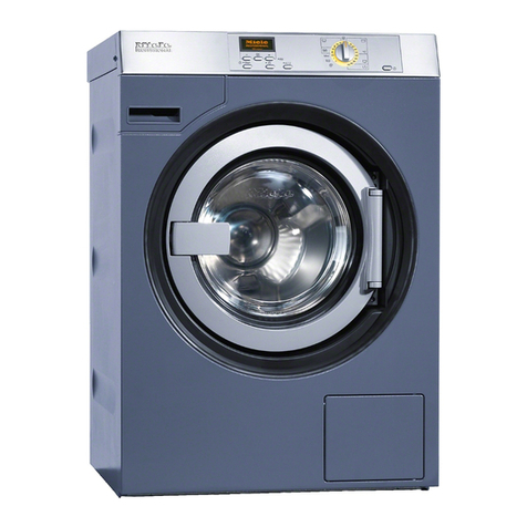
  9. Miele PW 6101 User manual

Miele PW 6101 User manual

PW 6101, PW 6131, PW 6161, PW 6201, PW 6107, PW 6137, PW 6167, PW 6207, PW 6241, PW 6321, WS 5101, WS 5141, WS 5191,
WS 5240, WS 5320
x
de Montageanweisung “Anschluss für
Wasserrückgewinnung”en Fitting instructions -
Connection for water recycling fr Notice de montage “Raccordement
du dispositif de recyclage de l'eau”
ni Montage-instructie "Aansluiting
voor waterterugwinning" da Monteringsanvisning
"Tilslutning til vandgenvinding" sv Monteringsanvisning
"Anslutning för vattenåtervinning"
fi Asennusohje Vedenkierrätyslait-
teen liitäntä es Instrucciones de montaje
“Conexión para recuperación
de agua”
am Water Recycling Connection
1
2
34
Produktgruppe 512 Umbau- und Montageanweisung
1 von 60 M.-Nr. 04598534
16.12.2011 Diese Unterlagen dürfen ohne unsere Genehmigung weder vervielfältigt noch Dritten zugänglich gemacht werden. Eigentumsrechte vorbehalten.
x
5
6
7
8
Produktgruppe 512 Umbau- und Montageanweisung
2 von 60 M.-Nr. 04598534
16.12.2011 Diese Unterlagen dürfen ohne unsere Genehmigung weder vervielfältigt noch Dritten zugänglich gemacht werden. Eigentumsrechte vorbehalten.
x
910
11 12
13
14
Produktgruppe 512 Umbau- und Montageanweisung
3 von 60 M.-Nr. 04598534
16.12.2011 Diese Unterlagen dürfen ohne unsere Genehmigung weder vervielfältigt noch Dritten zugänglich gemacht werden. Eigentumsrechte vorbehalten.
x
15
16
17
18
Produktgruppe 512 Umbau- und Montageanweisung
4 von 60 M.-Nr. 04598534
16.12.2011 Diese Unterlagen dürfen ohne unsere Genehmigung weder vervielfältigt noch Dritten zugänglich gemacht werden. Eigentumsrechte vorbehalten.
x
19
20
Produktgruppe 512 Umbau- und Montageanweisung
5 von 60 M.-Nr. 04598534
16.12.2011 Diese Unterlagen dürfen ohne unsere Genehmigung weder vervielfältigt noch Dritten zugänglich gemacht werden. Eigentumsrechte vorbehalten.
x
21
Produktgruppe 512 Umbau- und Montageanweisung
6 von 60 M.-Nr. 04598534
16.12.2011 Diese Unterlagen dürfen ohne unsere Genehmigung weder vervielfältigt noch Dritten zugänglich gemacht werden. Eigentumsrechte vorbehalten.
de
Benötigte Teile
x
Anzahl M.-Nr. Benennung
1 04451340 Umbausatz WRG02 Wasserrückgewinnung
Multifunktionsmodule PW 6xx1:
1 06252200 Montagesatz “MF03 10–20 Multifunktionsmodul PWxx1”
1 06252270 Montagesatz “MF05 10 Multifunktionsmodul PW101”
1 06252290 Montagesatz “MF05 13 Multifunktionsmodul PW131”
1 06252320 Montagesatz “MF05 16 Multifunktionsmodul PW161”
1 06252340 Montagesatz “MF05 20 Multifunktionsmodul PW201”
Multifunktionsmodule PW 6xx7:
1 09079460 Montagesatz “MF03 10–20 Multifunktionsmodul PWxx7”
1 09079470 Montagesatz “MF05 10–20 Multifunktionsmodul PWxx7”
Hinweis
Diese Umbauarbeiten dürfen grundsätzlich nur von einer Elektrofachkraft (fachliche Ausbildung, Fachkenntnisse und Facherfahrungen,
zeitnahe berufliche Tätigkeit) unter Berücksichtigung der gültigen Sicherheitsbestimmungen durchgeführt werden.
Für die Inbetriebnahme, Instandsetzung, Änderung, Prüfung und Wartung elektrischer Geräte sind die entsprechenden gesetzlichen
Grundlagen, Unfallverhütungsvorschriften, die gültigen Normen, die der Sicherheit dienen, sowie die am Aufstellungsort gültigen
Vorschriften der Energieversorgungsunternehmen zu beachten.
Gefahr!
Auch bei ausgeschaltetem Gerät kann Netzspannung an Bauteilen anliegen!
Deshalb ist, bevor Wartungsarbeiten, Instandsetzungsarbeiten oder Änderungen am Gerät durchgeführt werden, eine sichere
Netztrennung von allen aktiven, spannungsführenden Leitungen sowie anschließend eine Messung der Spannungsfreiheit erforderlich!
Grundsätzlich muss eine allgemeine Sichtprüfung und Gefährdungsbeurteilung durchgeführt werden.
Eine nicht fachgerechte Änderung kann zu einer Gefährdung führen (Brand, elektrischer Schlag usw.).
Gefahr!
Die Schutzleiterfunktion kann durch einen fehlerhaften Gehäusezusammenbau außer Kraft gesetzt werden.
Die Schutzleiterfunktion ist bei Montage der Gehäuseteile wieder herzustellen.
Elektrische Sicherheitsprüfung durchführen.
Gefahr!
Bei der Montage dürfen berührbare leitfähige Teile, die nicht am Schutzleiter angeschlossen sind, keine Schutzleiterverbindung haben
(verstärkte, doppelte Isolierung).
Der Nachweis ist durch Messen des ordnungsgemäßen Isolationswiderstandes und Berührungsstromes nachzuweisen.
Produktgruppe 512 Umbau- und Montageanweisung
7 von 60 M.-Nr. 04598534
16.12.2011 Diese Unterlagen dürfen ohne unsere Genehmigung weder vervielfältigt noch Dritten zugänglich gemacht werden. Eigentumsrechte vorbehalten.
Hinweis
Der Montagesatz M.-Nr. 04451340 für PW 610x, PW 613x , PW 616x und PW 620x enthält:
•1 Behälter
•1 Kappe
•1 Dichtring
•1 Klemmring
•1 Sechskantschraube M 8 x 150
•2 Scheibe 8,4
•1 Sechskantmutter M 8
•11 Verbindungsschlauch
•4 Verbindungsrohr 32 DRM x 1,5
•8 Schlauchschelle SGL 25-40
•1 Abzweigstück
•1 Schlauchschelle SGL 16-25
•1 Konsole octoblau
•1 Umlaufventil T 28, AB 81-A 04, 220 V / 50 Hz
•1 Kabelbaum Ablaufventil
•1 Gerätesteckdose GDM 20,11 grau
•1 Verbindungsrohr 32 DRM x 1,5
•6 Schlauchschelle SGL 40-60
•1 Filtergehäuse
•1 Flusensieb
•1 Deckel
•1 Griff
•2 Linsenblechschraube 4,2 x 9,5
•1 Tauchpumpe SPA 500
x
Hinweis
Der Montagesatz M.-Nr. 04451340 für PW 610x, PW 613x , PW 616x und PW 620x enthält weiterhin:
•1 Kabelhalter 98 x 2,5
•1 Kabelhalter 200 x 4,8
•2 Schlauchschelle SGT 25-40 / 9 DIN 3017
•1 Verbindungsrohr 32 DRM x 1,5
•1 Kabelverschraubung MZ PG 9 6-8
•1 Gegenmutter PG 9 MS
•1 Winkel
•4 Sechskantmutter Edelstahl M 5
•4 Scheibe Edelstahl B 5,3
•1 Bogen 70 x 87 PP
•1 Muffe DIN 19560, DN 70
•1 Bogen 70 x 87 PP
•2 Rohr DIN 19560 HTEM 70 x 150
•1 Abzweigrohr DIN 19560 70 x 70 x 87
•1 Rohr DIN 19560 HTEM 70 x 150
•1 Bogen 70 x 87 PP
•1 Winkel
•1 Ablaufventil MDB
•1 Kabelbaum Ablaufventil
•2 Sechskantblechschraube 4,2 x 13
•2 Blechmutter Edelstahl B 4,2
•1 Überlauf
•1 Ablaufgarnitur
•1 Bogen DIN 19560, 40 x 87
Produktgruppe 512 Umbau- und Montageanweisung
8 von 60 M.-Nr. 04598534
16.12.2011 Diese Unterlagen dürfen ohne unsere Genehmigung weder vervielfältigt noch Dritten zugänglich gemacht werden. Eigentumsrechte vorbehalten.
x
Hinweis
Der Montagesatz M.-Nr. 04451340 für PW 610x, PW 613x , PW 616x und PW 620x enthält weiterhin:
•1 Rohr 173 x 40
•2 Bogen 70 x 87 PP
•1 Abzweigrohr 70 x 50 x 87, DIN 19560
•1 Anschluss-Stutzen
•1 Manschette DIN 4060, HTGM 40/50 C
•1 Abzweigrohr
•1 Ring
•1 Anschluss-Stutzen
•2 Schlauchschelle SGL 70-90
•1 Abzweigrohr 70 x 50 x 87, DIN 19560
•1 Rohr DIN 19560, 50 x 40
•1 Bogen 70 x 87 PP
•8 Schlauch 11/4" 32 x 5,5
•1 Kabelbaum Wasserrückgewinng.
•1 Klemmleiste 6 polig
•1 Aufkleber 1-6,10 x 68
•2 Linsenblechschraube 3,5 x 11
•1 Zubehör- Begleitschriften
•1 Zubehör- Aufstellung
•1 Vorrüstung für Wasserrückgewinnung
•1 Schlauch Baugruppe WRG 02
•Diese Montageanweisung “Anschluss für Wasserrückgewinnung”
Liste der Abbildungen (PW 610x, PW 613x, PW 616x, PW 620x):
–Abb. 1, Abdeckblech Mischkasten abbauen
–Abb. 2, Schlauch Wasserablauf am Mischkasten abziehen
–Abb. 3, Wasserzulauf der Wasserrückgewinnung am Mischkasten
–Abb. 4, Wasserzulauf der Wasserrückgewinnung am Mischkasten aufbohren
–Abb. 5, Ansicht Wasserzulauf Wasserrückgewinnung vom Abdeckblech Flüssigdosierung
–Abb. 6, Wasserzulauf Wasserrückgewinnung
–Abb. 7, Abdeckblech Mischkasten anbauen
Liste der Abbildungen (PW 6241, PW 6321):
–Abb. 8, Verbindungsschlauch vormontieren
–Abb. 9, Laugenbehälter vorbereiten
–Abb. 10, Verbindungsschlauch verlegen
–Abb. 11, Befestigung Winkelstutzen und Halter
–Abb. 12, Verbindungsschlauch befestigen
–Abb. 13, Abdeckblech Mischkasten montiert
Liste der Abbildungen (WS 5101, WS 5141, WS 5191, WS 5240, WS 5320):
–Abb. 14, Verbindungsschlauch vormontieren
–Abb. 15, Montage in der Maschine
–Abb. 16, Zulaufschlauch WS 5101, WS 5141
Liste der Abbildungen (WRG 02 Wasserrückgewinnung montieren):
–Abb. 17, Konsole
–Abb. 18, Tank montieren
–Abb. 19, Tank mit Schlauchbögen
–Abb. 20, Filtereinheit komplettieren
–Abb. 21, Schlauchverbindungen
Produktgruppe 512 Umbau- und Montageanweisung
9 von 60 M.-Nr. 04598534
16.12.2011 Diese Unterlagen dürfen ohne unsere Genehmigung weder vervielfältigt noch Dritten zugänglich gemacht werden. Eigentumsrechte vorbehalten.
Anschluss für Wasserrückgewinnung PW 610x, PW 613x, PW 616x, PW 620x
–Die Maschine vom bestimmungsgemäßen Elektroanschluss trennen und gegen Wiedereinschalten sichern und Spannungsfreiheit
feststellen.
–Je eine Schrauben links und rechts auf der Oberseite des Deckels der Maschine herausdrehen.
–Den Deckel frontseitig handbreit anheben, nach hinten schieben, und dadurch die Zentrierkegel der Deckelrückseite aus der
Verbindungsleiste aushaken.
–Den Deckel nach oben vom Gehäuse abnehmen.
–Rückwand abbauen.
–Abdeckblech Mischkasten an der Geräterückwand abbauen, siehe Abb. 1.
–Die Schlauchschellen des Wasserablaufes lösen und den Schlauch abziehen, siehe Abb. 2.
–Den Wasserzulauf für den Anschluss der Wasserrückgewinnung auf ca. 28 mm Durchmesser aufbohren, siehe Abb. 4.
x
Achtung!
Die Bohrspäne am Wasserablauf des Mischkastens auffangen, siehe Abb. 2.
–Den Wasserzulauf mit Schlauchschelle am Anschlussstutzen Mischkasten aufstecken und Schelle verschrauben, siehe Abb. 6.
–Abdeckblech Mischkasten mit Durchführung für Zulaufflansch montieren, siehe Abb. 7.
–Den Schlauch des Wasserablaufes des Mischkastens aufstecken und die Schlauchschelle festziehen.
Anschluss für Wasserrückgewinnung PW 6241, PW 6321
–Die Maschine vom bestimmungsgemäßen Elektroanschluss trennen und gegen Wiedereinschalten sichern und Spannungsfreiheit
feststellen.
–Den Maschinendeckel abbauen.
–Rückwand abbauen.
–Abdeckblech Mischkasten an der Geräterückwand abbauen
–Verbindungsschlauch Laugenbehälter / Verbindungsleiste vormontieren, siehe Abb. 8.
x
Hinweis
Für die PW 6321 muß der Schlauch auf X1 = 80 mm gekürzt werden.
–Der Schlauch zur Verbindungsleiste auf X2 = 28,5 mm kürzen, siehe Abb. 8.
–Blindstopfen am Laugenbehälter entfernen.
–Zur Befestigung des Halters (Abb. 8, Pos. 1) in den Laugenbehälter ein Loch mit 6 mm Durchmesser bohren. Abstand zur
Rollnaht X = 110 mm, siehe Abb. 9.
–Verbindungsschlauch in der Maschine verlegen, siehe Abb. 10
–Winkelstutzen und Halter am Laugenbehälter montieren, siehe Abb. 11.
–Abdeckblech durch Öffnung in der Verbindungsleiste führen und montieren.
–Verbindungsschlauch mit Kabelbinder an den Wasserzuläufen befestigen, siehe Abb.12.
Anschluss für Wasserrückgewinnung WS 5101, WS 5141, WS 5191, WS 5240, WS 5320
–Die Maschine vom bestimmungsgemäßen Elektroanschluss trennen und gegen Wiedereinschalten sichern und Spannungsfreiheit
feststellen.
–Den Maschinendeckel abbauen.
–Rückwand abbauen.
–Abdeckblech Mischkasten an der Geräterückwand abbauen
Produktgruppe 512 Umbau- und Montageanweisung
10 von 60 M.-Nr. 04598534
16.12.2011 Diese Unterlagen dürfen ohne unsere Genehmigung weder vervielfältigt noch Dritten zugänglich gemacht werden. Eigentumsrechte vorbehalten.
x
X Y
WS 5101 280 280
WS 5141 280 280
WS 5191 340 203
WS 5240 476 205
WS 5320 317 205
Tabelle 1: Ablängmaße
–Verbindungsschlauch Laugenbehälter / Verbindungsleiste entsprechend Maschine ablängen und vormontieren, siehe Abb.14 und
Tabelle 1.
–Dichtung mit Blechscheibe aus dem Laugenbehälter entfernen. Dichtung weiterverwenden.
–Dichtung und Verbindungsschlauch in den Laugenbehälter einknüpfen und mit Schraube M 5 x 12, Scheibe und Mutter M 5
(selbstsichernd) montieren, siehe Abb. 15, Pos. 1.
–Stutzen des Verbindungsschlauches mit der Verbindungsleiste verschrauben, siehe Abb. 15, Pos. 2.
–Unwuchtschaltantenne bei WS 5101, WS 5141 um 45 mm kürzen.
WRG02 Wasserrückgewinnung montieren
Tank montieren:
x
Achtung!
Vor Montagebeginn die Tragfähigkeit der Montagewand prüfen. Gewicht Tank: ca. 200 kg
Hinweis
Maße der Konsolenposition vom Installationsplan übernehmen.
–Konsole als Schablone an die Wand halten und Bohrlöcher anzeichnen
–Bohrungen Durchmesser 10 mm bohren.
x
Achtung!
Beim Bohren die unterschiedlichen Höhenmaße beachten.
Hinweis
Der mitgelieferte Befestigungssatz kann für Beton ≥B 15 und ungelochten Mauerziegel ≥MZ 15 verwendet werden.
Für abweichende Montagewände sind entsprechende Befestigungssätze bauseitig zu beschaffen.
–In die oberen Befestigungsmuttern Schrauben M 6 x 16 eindrehen.
–Den Tank in die oberen Befestigungslöcher einhängen.
–Die restlichen Schrauben (6x) eindrehen und anziehen.
–Vormontierte Schlauchbögen mit Schlauchschellen 32-50 mm an der Behälterkappe befestigen, siehe Abb.19.
–Rohrstutzen (Abb. 19, Pos.1) in die Schlauchbögen einschieben und mit Schlauchschellen 32-50 mm befestigen.
x
Achtung!
Position des Belüftungsschlauches beachten
–Verbindungsschlauch mit Ablaufventil am Tank mit Schlauchschelle 40-60 mm anschließen.
–Ablaufbogen mit Schlauchschelle 40-60 mm am Ablaufventil befestigen.
Produktgruppe 512 Umbau- und Montageanweisung
11 von 60 M.-Nr. 04598534
16.12.2011 Diese Unterlagen dürfen ohne unsere Genehmigung weder vervielfältigt noch Dritten zugänglich gemacht werden. Eigentumsrechte vorbehalten.
Filtereinheit komplettieren:
–Rohrverbindung zum Anschluss an der Waschmaschine, siehe (Abb. 20, Pos. 1).
x
Hinweis
Rohr (Abb. 20, Pos. 4) kann entfallen bei Aufstellung der Filtereinheit hinter die Maschine.
Bei Aufstellung der Filtereinheit in Verbindung mit WS 5240, WS 5320 muß das beigelegte Rohr (Abb. 20, Pos. 4) zwischen Bogen
(Abb. 20, Pos. 2) und Muffe (Abb. 20, Pos. 3) montiert werden.
–Rohrverbindung zum Anschluss an den Tanküberlauf, siehe Abb. 20, Pos. 5.
–Rohrverbindung zum Anschluss an die bauseitge Ablaufinstallation (DN 70), siehe Abb. 20, Pos. 6.
–Rohrverbindung zum Anschluss der Tauchpumpe zum Tank, siehe Abb. 20, Pos. 7.
SchlauchverbindungenTank / Waschmaschine / Filtereinheit:
–Den Schlauch aus dem Beipack nach den örtlichen Begebenheiten zwischen Tank, Waschmaschine und Filtereinheit anpassen,
siehe Abb. 21.
x
Hinweis
Schlauchposition, siehe Abb. 21.
Verbindung zur Waschmaschine, siehe Abb. 21, Pos. 1.
–Angepasste Schläuche mit Schlauchschellen anbauen.
Anschluss der elektrischen Bauteile:
–Beiliegende 6 polige Klemmleiste gemäß Hinweiszettel Lageplan der Maschine montieren.
–Bezeichnungsstreifen 1-6 unter den Klemmstein legen.
–Eingewickelte Leitung aus dem Kabelbaum Steuerung auswickeln und gemäß Bedruckung anschließen.
x
Hinweis
Alternativ den beiliegenden Kabelbaum verdrahten
–Ablaufventil vom Tank, Tauchpumpe und Ablaufventil der Filtereinheit nach beiliegendem Schaltplan WRG an dem Klemmstein
anschließen.
–Schutzleiter an der Erdungsschraube des Geräteträgers anschließen.
–Leitungen mit Kabelbindern fixieren.
Arbeiten abschließen:
–Wasserführung auf Dichtigkeit prüfen und Probelauf durchführen.
–Schaltplan WRG dem Maschinenschaltplan beilegen.
–Rückwand anbauen.
–Den Deckel der Maschine anbauen.
–Elektrische Sicherheitsprüfung durchführen.
–Die Maschine an dem bestimmungsgemäßen Elektroanschluss anschließen.
de
Produktgruppe 512 Umbau- und Montageanweisung
12 von 60 M.-Nr. 04598534
16.12.2011 Diese Unterlagen dürfen ohne unsere Genehmigung weder vervielfältigt noch Dritten zugänglich gemacht werden. Eigentumsrechte vorbehalten.
en
Parts required
x
Quantity Mat. no. Designation
1 04451340 Conversion kit - WRG02 water recycling
Multifunction module PW 6xx1:
1 06252200 Fitting kit - MF03 10-20 multifunction module PWxx1
1 06252270 Fitting kit - MF05 10 multifunction module PW101
1 06252290 Fitting kit - MF05 13 multifunction module PW131
1 06252320 Fitting kit - MF05 16 multifunction module PW161
1 06252340 Fitting kit - MF05 20 multifunction module PW201
Multifunction module PW 6xx7:
1 09079460 Fitting kit - MF03 10-20 multifunction module PWxx7
1 09079470 Fitting kit - MF05 10-20 multifunction module PWxx7
Note
This service and repair work should only be carried out by a suitably qualified electrician (with specialist training, knowledge and
experience, and recent related work experience) in accordance with all appropriate local and national safety regulations.
Servicing, modification, testing and maintenance of electrical appliances should only be carried out in accordance with all appropriate
legal requirements, accident prevention regulations and valid standards. All regulations of the appropriate utility supply companies and
standards relating to safety (not limited to electrical safety) are to be complied with.
Danger!
Even with the machine switched off, mains voltage may be applied to some components.
Before any service work is commenced, the machine must be disconnected from the mains. Suitable measurements must be made to
ensure that this is the case.
A general visual check and risk evaluation should always be carried out.
Incorrect conversion or service work can be dangerous (risk of fire, electric shock, etc.).
Danger!
Correct earthing function can be deactivated if casing parts are incorrectly assembled.
Correct earthing function must be ensured when refitting the casing.
Carry out appropriate electrical safety checks.
Danger!
During fitting, all accessible conductive parts that are not connected to the earth must not have any link to earth (strengthened double
insulation).
To confirm this, insulation resistance and touch current measurements must be carried out.
Produktgruppe 512 Umbau- und Montageanweisung
13 von 60 M.-Nr. 04598534
16.12.2011 Diese Unterlagen dürfen ohne unsere Genehmigung weder vervielfältigt noch Dritten zugänglich gemacht werden. Eigentumsrechte vorbehalten.
Note
The kit, Mat. no. 04451340 for PW 610x, PW 613x, PW 616x and PW 620x, contains the following:
•1 container
•1 cap
•1 seal
•1 clamping ring
•1 bolt M8 x 150
•2 washers 8.4
•1 nut M8
•11 connection hoses
•4 connection pipes 32 mm dia. x 1.5
•8 hose clips SGL 25 - 40
•1 branch piece
•1 hose clip SGL 16 - 25
•1 mounting bracket, octoblue
•1 circulation valve T 28, AB 81-A 04, 220 V 50 Hz
•1 wiring harness - Drain valve
•1 machine socket GDM 20, 11 grey
•1 connection pipe 32 mm dia. x 1.5
•6 hose clips SGL 40 - 60
•1 filter housing
•1 fluff filter
•1 lid
•1 handle
•2 raised-head self-tapping screws 4.2 x 9.5
•1 immersion pump SPA 500
x
Note
The kit, Mat. no. 04451340 for PW 610x, PW 613x, PW 616x and PW 620x, also contains the following:
•1 cable holder 98 x 2.5
•1 cable holder 200 x 4.8
•2 hose clips SGT 25 - 40 / 9 DIN 3017
•1 connection pipe 32 mm dia. x 1.5
•1 cable screw connector MZ PG 9 6 - 8
•1 counter nut PG 9 MS
•1 bracket
•4 nuts, stainless steel, M5
•4 washers, stainless steel, B5.3
•1 bend 70 x 87 PP
•1 sleeve DIN 19560, dia. 70 mm
•1 bend 70 x 87 PP
•2 pipes DIN 19560 HTEM 70 x 150
•1 branch piece DIN 19560 70 x 70 x 87
•1 pipe DIN 19560 HTEM 70 x 150
•1 bend 70 x 87 PP
•1 bracket
•1 drain valve MDB
•1 wiring harness - Drain valve
•2 hexagonal-head self-tapping screws 4.2 x 13
•2 speed nuts, stainless steel, B4.2
•1 overflow
•1 drain set
•1 bend DIN 19560, 40 x 87
Produktgruppe 512 Umbau- und Montageanweisung
14 von 60 M.-Nr. 04598534
16.12.2011 Diese Unterlagen dürfen ohne unsere Genehmigung weder vervielfältigt noch Dritten zugänglich gemacht werden. Eigentumsrechte vorbehalten.
x
Note
The kit, Mat. no. 04451340 for PW 610x, PW 613x, PW 616x and PW 620x, also contains the following:
•1 pipe 173 x 40
•2 bends 70 x 87 PP
•1 branch piece 70 x 50 x 87, DIN 19560
•1 connection stub
•1 collar DIN 4060, HTGM 40/50 C
•1 branch piece
•1 ring
•1 connection stub
•2 hose clips SGL 70 - 90
•1 branch piece 70 x 50 x 87, DIN 19560
•1 pipe DIN 19560 50 x 40
•1 bend 70 x 87 PP
•8 hoses 11/4" 32 x 5.5
•1 wiring harness - Water recycling
•1 terminal strip, 6-pole
•1 sticker 1 - 6,10 x 68
•2 raised-head self-tapping screws 3.5 x 11
•1 accessory - Information sheet
•1 accessory - Installation
•1 initial kit for water recycling
•1 hose sub-assembly WRG 02
•These fitting instructions - Connection for water recycling
List of illustrations (PW 610x, PW 613x, PW 616x, PW 620x):
–Fig. 1: Mixer box cover plate removal
–Fig. 2: Drain hose disconnection from mixer box
–Fig. 3: Water recycling intake on mixer box
–Fig. 4: Drilling out water recycling intake on mixer box
–Fig. 5: Water recycling intake viewed from liquid dispensing cover plate
–Fig. 6: Water recycling intake
–Fig. 7: Mixer box cover plate fitting
List of illustrations (PW 6241, PW 6321):
–Fig. 8: Connection hose pre-assembly
–Fig. 9: Suds container preparation
–Fig. 10: Connection hose fitting
–Fig. 11: Angle connector fastening and holder
–Fig. 12: Connection hose fastening
–Fig. 13: Mixer box cover plate in fitted position
List of illustrations (WS 5101, WS 5141, WS 5191, WS 5240, WS 5320):
–Fig. 14: Connection hose pre-assembly
–Fig. 15: Fitting in the machine
–Fig. 16: Intake hose - WS 5101, WS 5141
List of illustrations (WRG 02 water recycling system fitting):
–Fig. 17: Mounting bracket
–Fig. 18: Tank fitting
–Fig. 19: Tank with angled hoses
–Fig. 20: Filter unit assembly
–Fig. 21: Hose connections
Produktgruppe 512 Umbau- und Montageanweisung
15 von 60 M.-Nr. 04598534
16.12.2011 Diese Unterlagen dürfen ohne unsere Genehmigung weder vervielfältigt noch Dritten zugänglich gemacht werden. Eigentumsrechte vorbehalten.
Connection for water recycling - PW 610x, PW 613x, PW 616x, PW 620x
–Disconnect the machine from the electric mains supply provided in accordance with all relevant regulations and ensure utilities
cannot be switched on again in error. Carry out a check to ensure that no power is supplied to the machine.
–Remove the screws on the left and right of the top of the lid.
–Lift the front of the lid slightly, slide it to the rear and thus release the centring cones at the rear of the lid from the connection strip.
–Remove the lid upwards.
–Remove the rear panel.
–Remove the mixer box cover plate on the rear of the machine, Fig. 1.
–Loosen the hose clip on the drain hose and disconnect the hose, Fig. 2.
–Drill out the water recycling intake on the mixer box to a diameter of approx. 28 mm, Fig. 4.
x
Warning!
Take care to collect and remove the drilling swarf at the mixer box drain outlet, Fig. 2.
–Fit the water intake hose with hose clip on the mixer box connection stub and tighten the hose clip, Fig. 6.
–Fit the mixer box cover plate with the throughfeed for the intake flange, Fig. 7.
–Refit the mixer box drain hose on the mixer box drain outlet and tighten the hose clip.
Connection for water recycling - PW 6241, PW 6321
–Disconnect the machine from the electric mains supply provided in accordance with all relevant regulations and ensure utilities
cannot be switched on again in error. Carry out a check to ensure that no power is supplied to the machine.
–Remove the machine lid.
–Remove the rear panel.
–Remove the mixer box cover plate on the rear of the machine.
–Pre-assemble the suds container / connection strip connection hose, Fig. 8.
x
Note
For the PW 6321 the hose must be shortened such that the dimension X1 = 80 mm.
–The hose to the connection strip must be shortened such that the dimension X2 = 28.5 mm, Fig. 8.
–Remove the blinding stopper on the suds container.
–To secure the holder, Fig. 8, Pos.1, drill a 6 mm hole in the suds container. Distance from rolled seam X = 110 mm, Fig. 9.
–Lay the connection hose in the machine, Fig. 10.
–Fit the angled connector and holder on the suds container, Fig. 11.
–Pass the cover plate through the opening in the connection strip and fit it.
–Fasten the connection hose with cable ties to the water intake hoses, Fig.12.
Connection for water recycling - WS 5101, WS 5141, WS 5191, WS 5240, WS 5320
–Disconnect the machine from the electric mains supply provided in accordance with all relevant regulations and ensure utilities
cannot be switched on again in error. Carry out a check to ensure that no power is supplied to the machine.
–Remove the machine lid.
–Remove the rear panel.
–Remove the mixer box cover plate on the rear of the machine.
Produktgruppe 512 Umbau- und Montageanweisung
16 von 60 M.-Nr. 04598534
16.12.2011 Diese Unterlagen dürfen ohne unsere Genehmigung weder vervielfältigt noch Dritten zugänglich gemacht werden. Eigentumsrechte vorbehalten.
x
X Y
WS 5101 280 280
WS 5141 280 280
WS 5191 340 203
WS 5240 476 205
WS 5320 317 205
Table 1: Trimming dimensions
–Shorten the suds container / connection strip connection hose depending on the machine in which it is to be fitted and carry out
pre-assembly, Fig. 14 and Table 1.
–Remove the seal with metal plate from the suds container. Reuse the seal.
–Fit the seal and connection hose in the suds container and secure with the M5 x 12 screw, washer and M5 nut (self-locking),
Fig. 15, Pos. 1.
–Connect the connection hose stub to the connection strip, Fig.15, Pos. 2.
–With the WS 5101, WS 5141, shorten the imbalance switch feeler by 45 mm.
WRG02 water recycling fitting
Tank fitting:
x
Warning!
Before commencing work, ensure that the wall can support the weight of the system. Weight of tank: Approx. 200 kg
Note
For mounting bracket positioning dimensions, see the installation plan.
–Hold the mounting bracket as a template on the wall and mark the positions where holes must be drilled.
–Drill 10 mm dia. holes.
x
Warning!
Note the different height dimensions when drilling the holes.
Note
The fastenings supplied can be used for German concrete quality ≥B 15 and solid brickwork German quality ≥MZ 15.
For other wall types, appropriate fastenings must be provided on site.
–Fit M6 x 16 bolts in the top fixing nuts.
–Hang the tank in the top fixing holes.
–Fit the remaining bolts (6x) and tighten them.
–Fasten the pre-assembled angled hoses to the container cap with 32 - 50 mm hose clips, Fig. 19.
–Slide the pipe connectors,Fig. 19, Pos.1, into the angled hoses and secure them with 32 - 50 mm hose clips.
x
Warning!
Note the position of the vent hose.
–Connect the connection hose with drain valve to the tank with a 40 - 60 mm hose clip.
–Connect the drain angled hose to the drain valve and secure it with a 40 - 60 mm hose clip.
Produktgruppe 512 Umbau- und Montageanweisung
17 von 60 M.-Nr. 04598534
16.12.2011 Diese Unterlagen dürfen ohne unsere Genehmigung weder vervielfältigt noch Dritten zugänglich gemacht werden. Eigentumsrechte vorbehalten.
Filter unit assembly:
–Pipe connection to connection on the washing machine,Fig. 20, Pos.1.
x
Note
The pipe, Fig. 20, Pos. 4, can be omitted if the filter unit is fitted behind the machine.
If the filter unit is fitted in conjunction with the WS 5240, WS 5320, the pipe provided, Fig. 20, Pos. 4, must be fitted between the
bend, Fig. 20, Pos. 2, and sleeve, Fig. 20, Pos. 3.
–Pipe connection to connection on the tank overflow, Fig. 20, Pos. 5.
–Pipe connection to on-site drain connection (dia. 70 mm), Fig. 20, Pos. 6.
–Pipe connection to immersion pump connection to the tank, Fig. 20, Pos. 7.
Hose connection tank / washing machine / filter unit:
–The hose supplied must be cut as necessary to suit the on-site conditions such that sections can be fitted between the tank, washing
machine and filter unit, Fig. 21.
x
Note
Hose positions, see Fig. 21.
For connection to washing machine, see Fig. 21, Pos. 1.
–Fit the prepared hoses with hose clips.
Connection of electrical components:
–Fit the 6-pole terminal strip supplied in accordance with the machine layout plan information sheet.
–Lay the designation strips 1 - 6 under the terminal block.
–Unwind the connection wires from the control wiring harness and connect them in accordance with their markings.
x
Note
Alternatively make connections with the wiring harness supplied.
–Connect the tank drain valve, immersion pump and filter unit drain valve to the terminal block in accordance with the water recycling
(WRG) wiring diagram supplied.
–Connect the earth conductor to the component bracket earth screw.
–Secure wires with cable ties.
Carry out final work:
–Check all water connections and paths for leaks and carry out a test run.
–Place the water recycling (WRG) wiring diagram with the machine wiring diagram.
–Refit the rear panel.
–Refit the machine lid.
–Carry out appropriate electrical safety checks.
–Reconnect the machine to the electric mains supply provided in accordance with all relevant regulations.
en
Produktgruppe 512 Umbau- und Montageanweisung
18 von 60 M.-Nr. 04598534
16.12.2011 Diese Unterlagen dürfen ohne unsere Genehmigung weder vervielfältigt noch Dritten zugänglich gemacht werden. Eigentumsrechte vorbehalten.
fr
Pièces nécessaires
x
Nombre Mat.-Nr. Désignation
1 04451340 Jeu d'adaptation WRG02 dispositif de recyclage de l'eau
Modules multifonctions PW 6xx1 :
1 06252200 Jeu de montage “MF03 10–20 Module multifonctions PWxx1”
1 06252270 Jeu de montage “MF05 10 Module multifonctions PW101”
1 06252290 Jeu de montage “MF05 13 Module multifonctions PW131”
1 06252320 Jeu de montage “MF05 16 Module multifonctions PW161”
1 06252340 Jeu de montage “MF05 20 Module multifonctions PW201”
Modules multifonctions PW 6xx7 :
1 09079460 Jeu de montage “MF03 10–20 Module multifonctions PWxx7”
1 09079470 Jeu de montage “MF05 10–20 Module multifonctions PWxx7”
Remarque
Ces travaux d'adaptation doivent être effectués exclusivement par un technicien qualifié (c'est à dire ayant suivi une formation
spécifique et disposant de connaissances et d'expériences récentes dans le domaine) respectant les prescriptions de sécurité en
vigueur.
La réglementation en vigueur, les prescriptions de prévention des accidents, les normes applicables de sécurité sur le lieu d'installation
ainsi que les prescriptions de la compagnie d'électricité doivent impérativement être respectées pour la mise en service, la réparation,
la modification, le contrôle et l'entretien des appareils électriques.
Danger !
Même si l'appareil est déconnecté, les composants peuvent présenter une tension résiduelle.
C'est pourquoi avant d'effectuer des travaux d'entretien ou de réparation ou encore des modifications sur l'appareil, il est nécessaire de
débrancher tous les câbles actifs et sous tension et d'effectuer une mesure pour s'assurer de l'absence de tension résiduelle !
Un contrôle visuel général et une évaluation des risques doivent impérativement être effectués.
Une modification non effectuée dans les règles peut avoir des conséquences dangereuses (incendie, électrocution, etc.)
Danger !
En cas de remontage de la carrosserie incorrect, le fonctionnement de la mise à la terre de l'appareil risque d'être désactivé.
Le fonctionnement de la mise à la terre doit être assuré après le montage des pièces de la carrosserie.
Effectuer un contrôle de sécurité électrique.
Danger !
Lors du montage, les pièces conductrices accessibles qui ne sont pas raccordées à la terre ne doivent pas être reliées à la terre
(isolation renforcée, double).
Ceci doit être vérifié en mesurant la résistance d'isolation et la résistance de contact.
Produktgruppe 512 Umbau- und Montageanweisung
19 von 60 M.-Nr. 04598534
16.12.2011 Diese Unterlagen dürfen ohne unsere Genehmigung weder vervielfältigt noch Dritten zugänglich gemacht werden. Eigentumsrechte vorbehalten.
Remarque
Le jeu de montage M.-Nr. 09079440 pour PW 610x, PW 613x, PW 616x et PW 620x contient :
•1 réservoir
•1 cache
•1 bague d'étanchéité
•1 bague de blocage
•1 vis à six pans M 8 x 150
•2 rondelles 8,4
•1 écrou six pans M8
•11 tuyaux de liaison
•4 tuyaux de raccordement 32 RDM x 1,5
•8 colliers de serrage SGL 25-40
•1 dérivation
•1 collier de serrage SGL 16-25
•1 console octobleu
•1 vanne de circulationT 28, AB 81-A 04, 220 V / 50 Hz
•1 toron clapet de vidange
•1 prise pour appareil GDM 20,11 gris
•1 tuyau de raccordement 32 RDM x 1,5
•6 collier de serrage SGL 40-60
•1 boîtier de filtre
•1 filtre
•1 couvercle
•1 poignée
•2 vis à tête ronde 4,2 x 9,5
•1 pompe plongeante SPA 500
x
Remarque
Le jeu de montage M.-Nr. 04451340 pour PW 610x, PW 613x , PW 616x et PW 620x contient également :
•1 passe-câble 98 x 2,5
•1 passe-câble 200 x 4,8
•2 colliers de serrage SGT 25-40 / 9 DIN 3017
•1 tuyau de raccordement 32 RDM x 1,5
•1 vissage de câble MZ PG 9 6-8
•1 contre-écrou PG 9 MS
•1 équerre
•4 écrous à six pans inox M 5
•4 rondelles inox B 5,3
•1 coude 70 x 87 PP
•1 manchon DIN 19560, DN 70
•1 coude 70 x 87 PP
•2 tuyaux DIN 19560 HTEM 70 x 150
•1 tuyau de dérivation DIN 19560 70 x 70 x 87
•1 tuyau DIN 19560 HTEM 70 x 150
•1 coude 70 x 87 PP
•1 équerre
•1 clapet de vidange MDB
•1 toron clapet de vidange
•2 vis à six pans 4,2 x13
•2 écrous inox B 4,2
•1 débordement
•1 garniture de vidange
•1 coude DIN 19560, 40 x 87
Produktgruppe 512 Umbau- und Montageanweisung
20 von 60 M.-Nr. 04598534
16.12.2011 Diese Unterlagen dürfen ohne unsere Genehmigung weder vervielfältigt noch Dritten zugänglich gemacht werden. Eigentumsrechte vorbehalten.

Other manuals for PW 6101

3

This manual suits for next models

14

Other Miele Washer manuals

Miele WWF 060 User manual

Miele

Miele WWF 060 User manual

Miele PWM 916 SD User manual

Miele

Miele PWM 916 SD User manual

Miele PWT 6089 Vario User manual

Miele

Miele PWT 6089 Vario User manual

Miele WKH 130 WPS User manual

Miele

Miele WKH 130 WPS User manual

Miele W 969 User manual

Miele

Miele W 969 User manual

Miele WDD030 WPS EcoPlus Comfort User manual

Miele

Miele WDD030 WPS EcoPlus Comfort User manual

Miele W 2122 User manual

Miele

Miele W 2122 User manual

Miele Premier Plus User manual

Miele

Miele Premier Plus User manual

Miele WWD320 WCS User manual

Miele

Miele WWD320 WCS User manual

Miele PW 6107 User manual

Miele

Miele PW 6107 User manual

Miele W 304 Plus User manual

Miele

Miele W 304 Plus User manual

Miele PW 6080 VARIO User manual

Miele

Miele PW 6080 VARIO User manual

Miele PWM 912 EL/RH User manual

Miele

Miele PWM 912 EL/RH User manual

Miele Touchtronic W 3033 Parts list manual

Miele

Miele Touchtronic W 3033 Parts list manual

Miele W 820 User manual

Miele

Miele W 820 User manual

Miele PW 6055 AV User manual

Miele

Miele PW 6055 AV User manual

Miele APCL 002 User manual

Miele

Miele APCL 002 User manual

Miele W 1119 User manual

Miele

Miele W 1119 User manual

Miele PW 6201 EL User manual

Miele

Miele PW 6201 EL User manual

Miele PW 6080 Vario User manual

Miele

Miele PW 6080 Vario User manual

Miele 11653560 User manual

Miele

Miele 11653560 User manual

Miele Paragon Plus User manual

Miele

Miele Paragon Plus User manual

Miele PW 6207 User manual

Miele

Miele PW 6207 User manual

Miele PG 8583 CD User manual

Miele

Miele PG 8583 CD User manual

Popular Washer manuals by other brands

Frigidaire ATFB7000ES1 operating instructions

Frigidaire

Frigidaire ATFB7000ES1 operating instructions

AEG OKO Lavamat 635 sensotronic operating instructions

AEG

AEG OKO Lavamat 635 sensotronic operating instructions

Whirlpool WTW8127LC quick start guide

Whirlpool

Whirlpool WTW8127LC quick start guide

LG FG1405S3W owner's manual

LG

LG FG1405S3W owner's manual

LG WM9000H A Series Service manual

LG

LG WM9000H A Series Service manual

Kelvinator KF836 Instruction book

Kelvinator

Kelvinator KF836 Instruction book

GE Profile WSXH208AWW installation instructions

GE

GE Profile WSXH208AWW installation instructions

Panasonic NA-F70B6 Operating & installation instructions

Panasonic

Panasonic NA-F70B6 Operating & installation instructions

Electrolux EWF 127570W user manual

Electrolux

Electrolux EWF 127570W user manual

Maytag Bravos MVWX500X user guide

Maytag

Maytag Bravos MVWX500X user guide

Elenberg MWM-1000 instruction manual

Elenberg

Elenberg MWM-1000 instruction manual

LG WM3997H series owner's manual

LG

LG WM3997H series owner's manual

Siemens WM08X160IN operating instructions

Siemens

Siemens WM08X160IN operating instructions

Dexter Laundry O Series Parts & service manual

Dexter Laundry

Dexter Laundry O Series Parts & service manual

Bosch WAS32794ME instruction manual

Bosch

Bosch WAS32794ME instruction manual

Hoover HTC 120 AA User instructions

Hoover

Hoover HTC 120 AA User instructions

Bosch WAK28161GB Instruction manual and installation instructions

Bosch

Bosch WAK28161GB Instruction manual and installation instructions

Kenmore 40249032011 installation instructions

Kenmore

Kenmore 40249032011 installation instructions

manuals.online logo
manuals.online logoBrands
  • About & Mission
  • Contact us
  • Privacy Policy
  • Terms and Conditions

Copyright 2025 Manuals.Online. All Rights Reserved.